Table of Contents
Advertisement
Available languages
Available languages
PROJECT SOURCE and logo design are
trademarks or registered trademarks of LF, LLC.
All rights reserved.
This toilet requires a 120V electrical outlet within 36-in of the unit.
Serial Number
Questions, problems, missing parts? Before returning to your retailer, call our customer
service department at (866) 389-8827, 8 a.m. - 8 p.m., EST, Monday - Sunday. You could
also contact us at partsplus@lowes.com.
SC22337
Purchase Date
1
ITEM #3854447/1054593
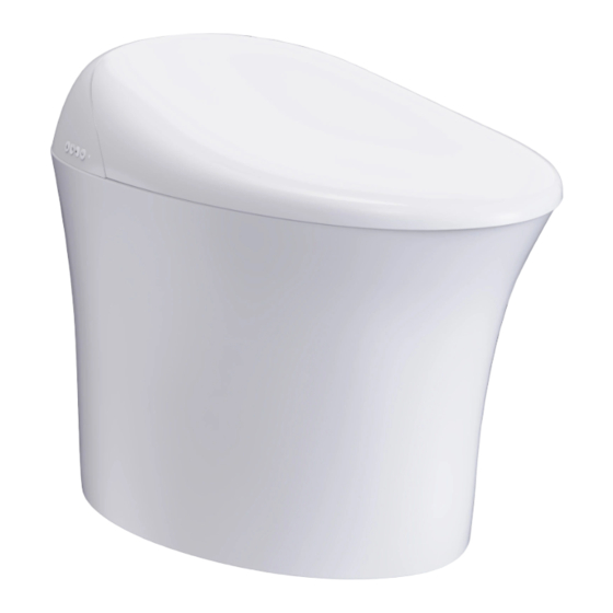
Bidet Toilet
MODEL #MT-25005L/MT-25005A
Español p. 22
Español p.
ATTACH YOUR RECEIPT HERE
XX
Advertisement
Chapters
Table of Contents

Subscribe to Our Youtube Channel
Related Manuals for Project Source MT-25005L


Summary of Contents for Project Source MT-25005L
- Page 1 Bidet Toilet MODEL #MT-25005L/MT-25005A Español p. 22 Español p. PROJECT SOURCE and logo design are trademarks or registered trademarks of LF, LLC. All rights reserved. ATTACH YOUR RECEIPT HERE This toilet requires a 120V electrical outlet within 36-in of the unit.
-
Page 2: Table Of Contents
TABLE OF CONTENTS Function Introduction........................2 Parts Diagram..........................3 Package Contents..........................3 Hardware Contents..........................4 Safety Precautions..........................5 Warning............................5 Caution...........................7 Preparation..........................8 Before Installation..........................8 Precautions For Installation and Use....................9 Installation ............................9 Remote Control - Basic Functions....................13 Troubleshooting......................17 Service and Clean..........................17 Inlet Water Strainer Cleaning......................18 Replace the Remote Control Battery....................19 Replace the Back-Up Battery.......................20 Warranty.......................20 Specifications....................21... -
Page 3: Parts Diagram
PARTS DIAGRAM Side Buttons On Toilet Power Plug Flush/Power Dryer Front Rear Wash Wash On/Off This product is designed to be operated mainly by the remote. The buttons on the side are used only when necessary. Side Operation Panel Ambient Light Warm Air Outlet Sensor Sit-Down... -
Page 4: Hardware Contents
HARDWARE CONTENTS T-Bolt Flat Washer Wing Nut Wax Ring Flat Metal Washer Qty. 2 Qty. 2 Qty. 2 Qty. 1 Qty. 2 AAA Batteries Wrench Angle Valve 9V - Seat Cover Battery Qty. 2 Qty. 1 Qty. 1 Qty. 1 15/16-in Connector 1/2-in Connector (OPTIONAL) -
Page 5: Safety Precautions
SAFETY PRECAUTIONS To prevent harm to users and others, as well as prevent property damage, please read and follow the Warnings and Cautions. WARNING: Means incorrect operation. Results of ignoring this sign could lead to risk for severe injury. CAUTION: Means incorrect operation. Results of ignoring this sign could lead to personal injury or property loss. - Page 6 WARNING FORBIDDEN ACTIONS • Please do NOT damage the power cord or plug. • Please do NOT forcefully throw, stretch, twist, bend, machine, heat, process, bind, or clamp power cords or inlet water hoses or put heavy things on them. •...
-
Page 7: Caution
MANDATORY ACTIONS WARNING • The power cord, if damaged, must be replaced by professionals from the manufacturer’s service department or similar departments. • Please make sure the distribution box power supply is turned off during service or inspection. Otherwise, electric shock or damage to parts may occur. *Exclude when “Spray Tip Cleaning”... -
Page 8: Preparation
FORBIDDEN ACTIONS CAUTION • When installing the water inlet strainer, please make sure it is correctly tightened. If not, water leakage may occur. • If the bowl becomes blocked, please trip the distribution panel breaker, then remove the blockage. Otherwise, sewage may spill out because of the automatic flush. •... -
Page 9: Precautions For Installation And Use
PRECAUTIONS FOR INSTALLATION AND USE 1. When installing the toilet, please do NOT pour cement mortar into ANY cavity of the toilet or elsewhere, to avoid cement setting and expanding to crack the toilet bottom. 2. Please do NOT discard into the toilet newspaper, diapers, sanitary pads, or other items that are likely to clog the toilet. - Page 10 TOILET INSTALLATION 3. Place the wax ring under the toilet. Parts Used Toilet Hardware Used Sewage Outlet Wax Ring 4. Install the floor bolts onto floor flange (not included). Position the toilet onto the floor flange (not included). Make sure the fixing bolts are aligned with the toilet holes.
- Page 11 TOILET INSTALLATION 5. Reconnect the water connection hoses on the toilet seat. Hand tighten the fitting and then turn an additional 1/4 turn with wrench. Parts Used Toilet Hardware Used Wrench 6. Re-install the toilet seat by aligning the two connection post and pressing firmly on the seat.
- Page 12 REMOTE CONTROLLER INSTALLATION 1. Tear the paper of the double-sided tape on the back of the bracket, stick the bracket on the wall. NOTE: Clean the installation position before pasting. Strongly and evenly press the tape when Wall pasting. Ready for use after 15 minutes. Remote Controller Parts Used...
-
Page 13: Remote Control - Basic Functions
CHECK TOILET BUTTONS 1. Confirm the power indicator on the side buttons light up. Side Button Icons Light NOTE: If the power indicator on the side buttons does Up After NOT light up, it means all functions are not working. Power-On Please use the remote or side buttons to power on the toilet. - Page 14 REMOTE CONTROL - BASIC FUNCTIONS 6. Fan • Press this button to start the fan and the indicator on the remote control will light up. Press this button again to end. 7. Nozzle Clean • Press this button to enter into nozzle cleaning mode. Water will flow out of the nozzle allowing you to clean it.
- Page 15 REMOTE CONTROL - BASIC FUNCTIONS 13. Water Temp • Press this button to enter water temp adjustment. There are 4 settings to choose from: Normal temp, Level 1, Level 2, Level 3. NOTE: Normal temp: No heat. • Idle mode means that the Rear Wash, Level 1: 91.4°F with 1 light on.
- Page 16 REMOTE CONTROL - BASIC FUNCTIONS 17. Flush/Auto Flush • Press this button once to Flush. The corresponding indicator will blink on the remote control. Press and hold for 3 seconds to start Auto Flush. After leaving the seat for 5 seconds, Auto Flush will flush the toilet once.
-
Page 17: Troubleshooting
BUZZER SOUNDS FROM TOILET • The toilet buzzer is a sound generating device and serves as a medium for the toilet to indicate the following: • Buzz 1: Somebody on seat, may respond to all operations. • Buzz 2: Nobody on seat, may respond to some operations. •... -
Page 18: Inlet Water Strainer Cleaning
SERVICE & CLEAN Spray Tip Cleaning and Servicing • Press 'Nozzle Clean' button and water sprays out. Press the button again to extend the rear nozzle. Then press again to extend the front nozzle. Clean the nozzles with a non-abrasive brush. NOTE: Don't forcefully pull or bend spray tips. -
Page 19: Replace The Remote Control Battery
CLEAN 1. Take out the strainer and remove the dirt from it. Flush it with tap water and brush with a cleaning toothbrush. NOTE: Please do NOT use any detergent; just water. Do NOT use too much force when cleaning, or the strainer may become bent or damaged. -
Page 20: Replace The Back-Up Battery
• Failures and damage caused by the use of unspecified power sources (voltage, frequency). • Used for purposes other than general domestic use. Project Source should not be liable for any loss caused by the fore said incorrect installation or use. -
Page 21: Specifications
SPECIFICATIONS Rated Voltage AC 120V, 50-60Hz 1280W (at inlet water temperature 41°F, and outlet water Maximum Power temperature and flow set at the top level) Rated Power 1200W(at inlet water temperature 59°F±32.9°F) Power Cord Length 4-ft 11.05-in 0.1 MPa (dynamic)-0.75MPa (static) (flow no less than 18L/min) Water pressure range 4-level adjustment Water pressure control... - Page 22 ARTÍCULO #3854447/1054593 Inodoro bidé MODELO #MT-25005L/MT-25005A PROJECT SOURCE y el diseño del logotipo son marcas comerciales o marcas comerciales registradas de LF, LLC. Todos los derechos reservados. ADJUNTE SU RECIBO AQUÍ Este inodoro requiere un tomacorriente de 120 V a menos de 91,44 cm de la unidad.
-
Page 23: Introducción A La Función
ÍNDICE Introducción a la función........................23 Diagrama de las piezas.........................24 Contenido del paquete........................24 Aditamentos..........................25 Precauciones de seguridad......................26 Advertencia............................26 Precaución..........................28 Preparación..........................29 Antes de la instalación........................29 Precauciones de instalación y uso....................30 Instalación .............................30 Control remoto - Funciones básicas....................34 Solución de problemas........................38 Mantenimiento y limpieza.......................38 Limpieza del filtro de agua de entrada....................39 Reemplazar la batería del control remoto..................40 Reemplazo de la batería de reserva....................41... -
Page 24: Diagrama De Las Piezas
DIAGRAMA DE LAS PIEZAS Botones laterales del inodoro Energía Tapón Descarga/Energía Secador Lavado Lavado posterior Encendido/apagado frontal Este producto está diseñado para usarse principalmente con el control remoto. Los botones laterales se usan solo en caso de ser necesario. Tapa Panel de funcionamiento lateral... -
Page 25: Aditamentos
ADITAMENTOS Perno en T Arandela plana Tuerca mariposa Aro de cera Arandela plana de metal Cant. 2 Cant. 2 Cant. 2 Cant. 1 Cant. 2 Baterías AAA Llave inglesa Válvula en ángulo Batería de la cubierta del asiento de 9 V Cant. -
Page 26: Precauciones De Seguridad
PRECAUCIONES DE SEGURIDAD Para evitar daños a los usuarios y a otras personas, así como daños materiales, lea y siga las advertencias y precauciones. ADVERTENCIA: significa funcionamiento incorrecto. Los resultados de ignorar esta señal pueden conllevar el riesgo de lesiones graves. PRECAUCIÓN: significa operación incorrecta. - Page 27 ADVERTENCIA ACCIONES PROHIBIDAS • NO dañe el cable de alimentación ni el enchufe. • NO arroje, estire, retuerza, doble, mecanice, caliente, procese, ate o sujete con fuerza los cables de alimentación o las mangueras de entrada de agua ni coloque objetos pesados sobre ellos. •...
-
Page 28: Precaución
ACCIONES OBLIGATORIAS ADVERTENCIA • Si el cable de alimentación está dañado, lo deben reemplazar profesionales del departamento de servicio del fabricante o departamentos similares. • Asegúrese de que el suministro de electricidad de la caja de distribución esté apagado durante el servicio o la inspección. De lo contrario, pueden producirse descargas eléctricas o daños en las piezas. -
Page 29: Preparación
ACCIONES PROHIBIDAS PRECAUCIÓN • Cuando instale el filtro de entrada de agua, asegúrese de que esté correctamente apretado. Si no lo está, pueden producirse filtraciones de agua. • Si la taza se bloquea, active el interruptor del panel de distribución y, luego, elimine la obstrucción. -
Page 30: Precauciones De Instalación Y Uso
PRECAUCIONES DE INSTALACIÓN Y USO 1. Cuando instale el inodoro, NO vierta mortero de cemento en ninguna cavidad delante del inodoro ni en ningún otro lado. De esa manera, evita que la aplicación y expansión del cemento agrieten la parte inferior del inodoro. 2. - Page 31 INSTALACIÓN DEL INODORO 3. Coloque el aro de cera debajo del inodoro. Piezas utilizadas Inodoro Aditamentos utilizados Salida de las Aro de cera aguas residuales 4. Instale los pernos del piso en la brida del piso (no incluido). Coloque el inodoro sobre la brida del piso (no incluido).
- Page 32 INSTALACIÓN DEL INODORO 5. Vuelva a conectar las mangueras de conexión de agua en el asiento para inodoro. Apriete a mano el conector y luego gire 1/4 de vuelta adicional con una llave inglesa. Piezas utilizadas Inodoro Aditamentos utilizados Llave inglesa 6.
- Page 33 INSTALACIÓN DEL CONTROL REMOTO 1. Rasgue el papel de la cinta doble faz en la parte posterior del soporte y pegue el soporte en la pared. NOTA: limpie la posición de instalación antes Pared pegar. Presione la cinta adhesiva de manera firme y uniforme al pegar.
-
Page 34: Control Remoto - Funciones Básicas
VERIFICAR LOS BOTONES DEL INODORO 1. Confirme que el indicador de encendido de los botones Los iconos de los laterales esté encendido. botones laterales se iluminan NOTA: si el indicador de encendido de los botones laterales después del NO enciende, significa que no todas las funciones están encendido funcionando. - Page 35 CONTROL REMOTO - FUNCIONES BÁSICAS 6. Ventilador • Presione este botón para iniciar el ventilador y el indicador en el control remoto se encenderá. Presione este botón de nuevo para finalizar. 7 Limpieza de la boquilla • Presione este botón para ingresar en el modo de limpieza de la boquilla. Saldrá agua de la boquilla para que pueda limpiarla.
- Page 36 CONTROL REMOTO - FUNCIONES BÁSICAS 13. Temperatura del agua • Presione este botón para ingresar el ajuste de la temperatura del agua. Hay 4 ajustes para elegir: Temperatura normal, nivel 1, nivel 2, nivel 3. NOTA: En temperatura normal, no se genera calor. •...
- Page 37 CONTROL REMOTO - FUNCIONES BÁSICAS 17. Descarga/Descarga automática • Presione este botón una vez para descargar. El indicador correspondiente titilará en el control remoto. Manténgalo presionado durante 3 segundos para iniciar la descarga automática. Después de salir del asiento durante 5 segundos, la descarga automática descargará el inodoro una vez. Vuelva a mantener presionado este botón para cancelar la descarga automática.
-
Page 38: Solución De Problemas
SONIDOS DEL ZUMBADOR DESDE EL INODORO • El zumbador del inodoro es un dispositivo que genera sonido y sirve como medio para que el inodoro indique lo siguiente: • Zumbido 1: alguien está en el asiento, puede responder a todas las operaciones. •... -
Page 39: Limpieza Del Filtro De Agua De Entrada
MANTENIMIENTO Y LIMPIEZA Limpieza y mantenimiento de la boquilla rociadora • Presione el botón "Nozzle Clean" (Limpieza de la boquilla) para que salga agua. Vuelva a presionar el botón para que la boquilla posterior se extienda. Luego, presione el botón nuevamente para que la boquilla frontal también se extienda. -
Page 40: Reemplazar La Batería Del Control Remoto
LIMPIAR 1. Saque el filtro y elimine la suciedad. Enjuáguelo con agua del grifo y cepíllelo con un cepillo de dientes. NOTA: NO use ningún detergente; use solo agua. NO ejerza demasiada fuerza al limpiar. De lo contrario, el filtro podría doblarse o dañarse. VOLVER A INSTALAR 1. -
Page 41: Reemplazo De La Batería De Reserva
• Fallas y daños causados por el uso de fuentes de alimentación no especificadas (voltaje, frecuencia). • Se utilizó para fines distintos del uso doméstico general. Project Source no será responsable de ninguna pérdida causada por dicha instalación o uso incorrectos. -
Page 42: Especificaciones
ESPECIFICACIONES Rango de voltaje 120 V CA, 50-60 Hz 1280 W (a una temperatura del agua de entrada de 5 °C y la Potencia máxima temperatura y el flujo del agua de salida establecidos en el nivel superior) Potencia nominal 1200 W (a una temperatura del agua de entrada de 15 °C ±...
Need help?
Do you have a question about the MT-25005L and is the answer not in the manual?
Questions and answers