Table of Contents
Advertisement
Quick Links
Advertisement
Table of Contents

Subscribe to Our Youtube Channel
Related Manuals for TKH SVS-Vistek GiGE VISION EoSens QUAD1.1S


Summary of Contents for TKH SVS-Vistek GiGE VISION EoSens QUAD1.1S
- Page 1 EoSens® QUAD1.1S User Guide Valid for VisualMARC2 Software version 2.3.x...
-
Page 2: Table Of Contents
Contents Before you start About this manual 1.1.1 Tips, remarks, and notes 1.1.2 Registered trademarks 1.1.3 Conformity and use 1.1.4 Supplements Warranty and non-warranty clause Support Introduction Intended use Scope of delivery Optional accessories System requirements The camera Camera description 3.1.1 Identification plate 3.1.2... - Page 3 The VisualMARC2 software Introduction 5.1.1 About the VisualMARC2 software 5.1.2 Prerequisites 5.1.3 System requirements 5.1.4 Installing the software The user interface 5.2.1 Overview 5.2.2 Start communicating with the camera 5.2.3 The workspace 5.2.4 Status bar entries The global function tabs 5.3.1 The Connection Manager tab 5.3.2...
- Page 4 5.7.5 The ImageBLITZ panel 5.7.6 The Trigger Control panel 5.7.7 The Advanced Settings panel 5.7.8 The Expert Settings panel 5.7.9 The Camera User Sets panel Technical data Camera specifications Sensor specifications Resolution and frame rate Camera dimensions Spectral response 6.5.1 Monochrome and color Appendix Declaration of Conformity...
- Page 5 Figures Fig.: 3-1: Interfaces of the camera EoSens® QUAD1.1S Fig.: 3-2: LEDs Fig.: 5-1: Connection Manager Fig.: 5-2: The workspace Fig.: 5-3: The Connection Manager tab Fig.: 5-4: About tab Fig.: 5-5: The Application settings tab Fig.: 5-6: The tools bar Fig.: 5-7: Image processing and analysis tabs Fig.: 5-8: Cropping the frame Fig.: 5-9: Flipping and rotating a frame...
- Page 6 Fig.: 5-34: Record Settings panel Fig.: 5-35: Autosave in ring mode Fig.: 5-36: ImageBLITZ split view Fig.: 5-37: ImageBLITZ panel Fig.: 5-38: The Trigger control panel Fig.: 5-39: The Digital Input section of the Trigger Control panel Fig.: 5-40: Digital input example Fig.: 5-41: The Digital Output section of the Trigger Control panel Fig.: 5-42: Advanced Settings panel Fig.: 5-43: Black level settings (example)
-
Page 7: Before You Start
Before you start About this manual This manual contains helpful information to install and operate the described cam- era. It has been produced with care. Nevertheless, information might be erroneous or incomplete. Mikrotron GmbH cannot be held responsible for any problems resulting from incomplete or erroneous information. -
Page 8: Supplements
This equipment generates, uses, and can radiate radio frequency energy and, if not installed and used in accordance with the instructions given in this guide, may cause harmful interference to radio communications. Operation of this equipment in a res- idential area is likely to cause harmful interference in which case the user will have to correct the interference at its own expense. -
Page 9: Warranty And Non-Warranty Clause
Life support applications The products described in this manual are not designed for use in life support appli- ances or devices and systems where malfunction of these products can reasonably be expected to result in personal injury. NOTICE Mikrotron customers using or selling these products for use in such applications do so at their own risk and agree to fully indemnify Mikrotron for any damages res- ulting from such improper use or sale. -
Page 10: Introduction
Introduction Intended use The camera EoSens® QUAD1.1S belongs to the product class of so-called record- ing cameras that can be used for a variety for purposes. Recording cameras are designed to capture and record fast movement, processes or short events and replay at slower speed, for example for slow-motion replay of move- ments in sports, during manufacturing processes, or for scientific research. - Page 11 Windows 7/8/10 (or higher) operating system 1 Gbit Ethernet controller 100 / 1000 BaseT to control the camera In order to reach high data transfer rates via Ethernet, the Ethernet controller should support jumbo frames that can carry up more than 8 kB of payload. Either VisualMARC2 software or a GenICAM SDK INFO EoSens®...
-
Page 12: The Camera
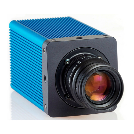
The camera Camera description The QUAD1.1S camera is our first member of a new generation of high-speed recording cameras. Considering the performance of the camera, it is rather compact. The C-mount ver- sion can easily be integrated into small spaces. Providing a high download speed via the GigE interface the frames are presented without delay on the PC screen. -
Page 13: Identification Plate
3.1.1 Identification plate The back of the camera provides a product label that displays the following inform- ation: Camera name Article description Serial number (e.g. S/N00002) If your camera is equipped with optional features, the identification plate will show the appropriate abbreviation(s): Abbreviation Meaning Color... -
Page 14: Additional Cooling
Additional cooling INFO If the camera is e.g. mounted on a sturdy aluminum structure, not only cooling is ensured but also a stable optical path. In addition, vibrations will be minimized within the entire system. If the ambient temperature is constantly exceeding 40 °C, additional cooling is recom- mended. -
Page 15: Status Led
3.4.1 Status LED The LEDs are described from left to right. Fig.: 3-2: LEDs 1 Status LED 2 Power LED 3 Recording LED 4 Not used 5 Not used Status LED Color Status Description Camera in idle mode blue 1 Hz* Camera transfers data to PC 10 Hz* ERROR... -
Page 16: Gige Interface
Recording LED Color Status Description – Acquisition stopped orange Waiting green Frame rate Recording frequency Table: 3-3: Recording LED *) Pulse = blinking 20% on state **) Pulse inv. = blinking 80% on state 3.4.2 GigE interface INFO We recommend to use the setting "Jumbo Packet" (see "Accelerating the network speed"... -
Page 17: Table: 3-4: Pin Assignment Of The External I/O Connector
The external I/O connector 16-pin Lemosa (EYG.1B.316.CLN) provides the fol- lowing signals: Pin No. Signal Description 0-10 V@ 1 MΩ analog input 0; 12 bit resolution I/O GND ground LVTTL GPS antenna 5 V TTL digital output 0 digital output 1 0 …... -
Page 18: First Steps
First steps Connecting the camera When using a GenICAM SDK, have the documentation of the SDK ready. Connecting the camera INFO In multi-camera mode we recommend to connect all cameras via a switch with the Ethernet controller of your PC. 1. -
Page 19: Manually Assigning An Ip Address
Pin No. Signal Description Connector pinning +10 to 30 V +10 to 30 V (STBY) not yet available Table: 4-1: Connector pinning Manually assigning an IP address The image processing system (e.g. PC) communicates with the camera via Ethernet. Therefore, an appropriate IP address must be assigned to the network card. In most cases, the IP address will be assigned automatically after connecting a cam- era. -
Page 20: Accelerating The Network Speed
5. Select Properties. 6. Check if Internet Protocol Version 4 (TCP / IPv4) is enabled. 7. Select Properties. 8. Assign a valid IP-address that is currently not in use, e.g. "192.168.110.1", sub- net-mask: "255.255.255.0". 9. Click OK. Accelerating the network speed If the network speed is not fast enough, you should set it to 1000 ... - Page 21 1. Open Network and Sharing Center in the Windows Control panel. 2. Select LAN connection. 3. Select Properties. 4. Select Configure. 4 First steps...
-
Page 22: Using Multiple Network Cards
5. Open the tab Advanced. 6. Select Jumbo Packet. If Jumbo Packet is not available, select Link Speed & Duplex and set the value to "1000 Mbps Full Duplex". 7. Click OK. Using multiple network cards When using multiple network cards, it is necessary to assign an IP-address to each. Proceed for each card as described below and make sure that the subnet of the two differs. -
Page 23: Resetting The Gige Link
Resetting the GigE link If an existing GigE Vision connection between camera and host PC gets lost by either PC or camera (e.g. EMC related), you can reset the GigE Vision related parts in the camera separately by performing a link reset and re-establish the connection after- wards. -
Page 24: The Visualmarc2 Software
The VisualMARC2 software Introduction 5.1.1 About the VisualMARC2 software VisualMARC2 enables you to set various parameters to control Mikrotron cameras and process the recorded images. In addition, the software has the following fea- tures: Compatible to Mikrotron Director2 software (for loading Director2 *.REC files) Clearly structured menus and functionality to enhance intuitive working Features for fast loading, storing, processing and analysis of image data 5.1.2... -
Page 25: The User Interface
3. Double click the file setup.exe. 4. Follow the instructions of the installation wizard to install the software on the image processing system. 5. Start the software on the desktop or in the Windows Start menu. The user interface 5.2.1 Overview This section provides general information about: How to start communicating with the camera (see... - Page 26 ig.: 5-2: The workspace 1 Global functions tabs (see "The 2 Window tabs (see "Toggle, move, or global function tabs" on page rearrange image tabs" on the next page) 3 Tools bar (see "The Tools bar" on 4 Image processing and analysis page ...
- Page 27 1. Click Hide on the bar left of the panels. 2. Click Show to display the panels. 3. To show or hide an individual panel, click on the triangle next to the panel name. Show or hide the recording and live control bar The recording control bar can be shown or hidden.
-
Page 28: Status Bar Entries
5.2.4 Status bar entries The status bar at the bottom of the workspace during live stream events displays a defined set of information, depending on the camera type. Status Stopped, Live, Recording, Playing (this information is not exported) Date Date of frame Time Time of frame Width... -
Page 29: The Import Tab
Fig.: 5-3: The Connection Manager tab The red color of the connector button indicates that the camera is not yet com- municating with the software. 1. Open the Connection Manager tab in the global function to check the con- nection status. The camera model, the manufacturer name, and the serial num- ber ("#0000xxx") of the connected cameras are displayed. -
Page 30: The Export Tab
3. Select the file to be imported. 4. Select Open or open the file by double-clicking. As soon as the image or video has been imported, it will be displayed in the window and an additional tab is displayed. 5.3.3 The Export tab The software supports the export of a single file or multiple files concurrently. -
Page 31: The "About" Tab
5.3.4 The “About” tab Fig.: 5-4: About tab The “About” tab displays the installed VisualMARC2 version, the email address for support requests, and Mikrotron web address. INFO The version number of the current build is also displayed in the window top bar. Additionally, a column indicates whether all necessary software components are installed in column "Status". -
Page 32: The Tools Bar
The Tools bar 5.4.1 Overview Fig.: 5-6: The tools bar The tools bar provides quick access to image editing functions. After clicking at a tool bar icon, the corresponding command will be executed imme- diately. 5 The VisualMARC2 software... -
Page 33: The Tools Bar Icons
5.4.2 The Tools bar icons Icon Function Toggle Crop View: Starts or stops cropping the selected image. When cropping, the image window is divided into the raw (original) view and the output (cropped) view. The raw view displays the image "as is" (i.e. without editing such as color corrections) The region of interest (ROI) to be cropped can be selected with the mouse. -
Page 34: Table: 5-3: Key Assignment
Description Go to selection start/stop "Selections" on page 59 100 frames forward Clicking a position in a slider and pressing the button increases the value by 100. 100 frames backward Clicking a position in a slider and pressing the button decreases the value by 100. -
Page 35: The Image Processing And Analysis Tabs
The image processing and analysis tabs 5.5.1 Overview Fig.: 5-7: Image processing and analysis tabs The image processing and analysis tabs display several tabs to process recorded images. INFO The availability of a tab depends on the camera connected (monochrome or color). If the color camera delivers RAW data, an additional Debayering tab is displayed. -
Page 36: Color Management
Cropping the frame Fig.: 5-8: Cropping the frame INFO When adjusting the cropped window with the mouse, size and offset of the cropped window are displayed in the Resize/Rotate tab. 1. For cropping the frame with the mouse, enable the crop selector or click the crop view icon and move the cropping area to the desired position. - Page 37 INFO For each pixel the recorded tonal value is stored in the image file along with the color. 8-bit monochrome images consist of 256 tonal values (8 bit per pixel), 10-bit monochrome images consist of 1024 tonal values. 8-bit color images can display 256 different tonal values per color channel (red, green, blue) and 10-bit color images display 1024 tonal values per color channel.
- Page 38 By changing the values for each color channel, white balance can be adjusted manu- ally. 1. Start by holding a white sheet of paper in front of the center of the camera lens. 2. To change the white balance for the red, green, or blue channel, move the slider or enter a value in the text box.
- Page 39 Neutral setting of the red channel is 1.00. Check the his- togram when changing the value. Green Neutral setting of the red channel is 1.00. Check the his- togram when changing the value. Blue Neutral setting of the red channel is 1.00. Check the his- togram when changing the value.
-
Page 40: Fig.: 5-10: Image Type Conversion
Image Type Conversion Fig.: 5-10: Image type conversion Recorded images can be converted into another gray or color format. This might be helpful if the software used for processing the recorded images requires BGR32 but recording is done in RGB24 or vice versa. All image formats can be converted in one of the four formats described below. -
Page 41: Fig.: 5-11: Color Transform Panel
Each pixel value of the color is multiplied with the factor in the matrix field and summarized. x 1 + G x 0 + B x 0 + Offset = new R value x 0 + G x 1 + B x 0 + Offset = new G value x 0 + G x 0 + B... -
Page 42: Fig.: 5-13: Color Transformation To Sepia
In example 1 the colored picture on the previous page was converted into sepia (see picture below). Each pixel value of the color was multiplied with the factor in the matrix field and sum- marized in each color channel. Fig.: 5-13: Color transformation to sepia Example 2 This is the original image with the untouched matrix: Fig.: 5-14: Color transformation, example 2... -
Page 43: Fig.: 5-15: Color Transformation Applied
x 1 + G x 1 + B x 0 + Offset 0 x 1 + G x 0 + B x 1 + Offset 0 Fig.: 5-15: Color transformation applied Adjustment Images can be processed e.g. to increase the visibility of certain details. Fig.: 5-16: Adjustment panel 1. -
Page 44: Fig.: 5-17: Linear Brightness
Fig.: 5-17: Linear brightness Brightness in the right picture was increased to the value 25. The left histogram shows the brightness values of the original image, the right one dis- plays the values of the brightened image. In the latter the values on the y-axis are lower than before, i.e. -
Page 45: Fig.: 5-19: Gamma Correction (Example)
Gamma correction Gamma correction is a non-linear method to adjust the brightness of an image. This method comes close to the manner the human eye perceives light and color. Increased brightness (linear) Increased brightness (non-linear) Fig.: 5-19: Gamma correction (example) Brightness of the original image was increased linear by the value 22 in the left image. -
Page 46: Histograms
Fig.: 5-21: Decreased saturation to 50 with histogram Fig.: 5-22: Increased saturation to 190 with histogram 5.5.5 Histograms Monitoring the histogram is an easy way to understand what happens when changing an image. A histogram shows the available pixel values and its distribution within the image. - Page 47 In rectangle view the pixel values from 0 (black) to 255 (white) are displayed along the x-axis. Along the y-axis, the frequency of each pixel value is displayed. INFO The height of the y-axis in the histogram will be automatically adjusted to the highest distribution value.
- Page 48 If [Show Source] is disabled, the values of the first vertical line (vertical reference 1), the first horizontal column is highlighted. 1. To check another line or column, disable Show Source. 2. In line view, move the line with the mouse to check each line separately. INFO Click at a color channel in the histogram to switch it off.
-
Page 49: Fig.: 5-24: Pixel Value Frequency
Frequency of pixel values The frequency of the different pixel values is explained in the next image where the gray part in the middle is larger than the black or white part on the sides. Fig.: 5-24: Pixel value frequency As the gray field in the middle of the image is larger than the other two fields, the fre- quency peak on the y-axis is higher for this field. - Page 50 The next image contains much more gray values. They are represented within the his- togram accordingly. Conversion into other formats If the image used in the section "Gray8 and Gray16 images" on page 46 with a res- olution of 418 x 64 is converted into or saved as BGR24 format, the three pixel val- ues in the histogram remain the same but statistical values will change.
- Page 51 96 pixels 480 pixels The first histogram below shows all pixel values from the brightest value to the darkest (158 to 227) on the x-axis and their distribution on the y-axis. The highest peak of the y-axis shows that 1,389 pixels of the value 196 have been counted in the gradient of gray shades above.
-
Page 52: Markers
In the picture below, value R254, G111, B109 represents a sort of pinkish color. This pixel can be found on x = 1012 and y = 886. Fig.: 5-25: Adjusting colors in histograms Using the histogram allows watching all changes offered by the color Management functions. -
Page 53: Fig.: 5-27: Setting Markers
Marker types Line Draws a straight line. Arrow Inserts an arrow. The end point is the arrow point. Rectangle Draws a rectangular shape. Ellipse Draws an elliptical shape. Text Inserts a text into a text box. Inserting a marker INFO To use colored markers in monochrome frames, the frame must be converted into a color image, which will increase the file size. -
Page 54: Info Field
1. Enable Grid to display the grid overlay in the image. 2. Define the vertical and horizontal grid spacing as well as the color of the grid lines. Resetting, deselecting, and deleting markers Reset returns all settings to the default values. Clicking at any point in the image deselects the marker. -
Page 55: The Recording And Live View Control Bar
The field A displays the value of a signal divided by 4096. X is the A/D converter value (12 bit). B is the offset value. [Unit] displays the unit of the converted value. [Format] displays the resulting values after the decimal point is set. 3. -
Page 56: Playback
Meaning 1 Toggles to live view and starts live image streaming of the selected scene. 2 Starts a recording of the current scene. Optionally, recording can be started pressing F5. During recording the bar displays the stop button (6), the software trigger button (7, if configured), and the abort button (8). 3 Rewind to the start in playback mode (see "Playback"... -
Page 57: Exporting Frames
INFO If you want to use keys for browsing, see "Assignment of keys" on page There are four playback options: 1 Browse backward frame by frame 2 Play backward 3 Play forward 4 Browse forward frame by frame 5 Displays the number of the current frame during playback or browsing. You can also jump directly to a frame by entering the frame index num- ber in the frame index field and pressing [ENTER]. -
Page 58: Table: 5-4: Export Formats
Format Description AVI Movie (H264) Audio Video Interleave (AVI) is Microsoft’s multimedia con- tainer format. It is compressed according to H.264 stand- AVI Movie (uncom- Uncompressed Audio Video Interleave (AVI) container pressed) format Uncompressed bitmap JPEG Compressed image format; select the quality of the JPEG file by moving the slider Bitmap image format that employs loss-free data com- pression... -
Page 59: Selections
3. Define your settings according to the output format. The displayed options depend on the selected output format. Selected Images: See "Selections" below Export Path: the directory path in which the files should be stored. To create a subfolder, Create Subfolder: when exporting an image series, select the option "Create Subfolder"... -
Page 60: Events
Navigating and deleting selections To play the selection forward or backward, select To jump between the selections, select To delete a single selection, click into the selection and select To delete all selections, select 5.6.6 Events Labeling helps to remember important events in a sequence. Events are exported in *.REC format. -
Page 61: The Device Control Panels
The device control panels 5.7.1 Overview Fig.: 5-29: The Device Control panels The panels in the device control panels are used for camera and recording settings for the camera connected. Camera Info shows the available data about the connected camera (see "The Camera Info panel"... -
Page 62: The Camera Info Panel
5.7.2 The Camera Info panel Fig.: 5-30: Camera Info panel The Camera Info panel displays information about the connected camera and allows to name the camera. INFO When the camera is unnamed, the MAC-address is displayed. Manufacturer displays the camera manufacturer's name. Camera Model displays the device name. -
Page 63: Fig.: 5-32: The Camera Settings Panel
If a camera is connected the settings of the current camera are displayed: Frame size: Displays the current frame size. Frame rate: Displays the current frame rate (see "Defining the camera settings" below). Exposure time: Displays the current exposure time (see "Defining the camera set- tings"... -
Page 64: Fig.: 5-33: Roi Split View
Adjusting the ROI If only a part of the frame is supposed to be inspected a certain area within a frame can be defined by setting a ROI (Region Of Interest). The smaller the height of the ROI, the higher the maximum frame rate. INFO Before changing the ROI, save all frames to a file. -
Page 65: The Record Settings Panel
The complete sensor area is covered, the ROI is maximized. Extends the width of the ROI area to the full sensor width. Deletes the changes and closes the ROI split view. Applies the settings and closes the ROI split view. 5.7.4 The Record Settings panel In the Record Settings panel the number of frames that can be recorded in one... -
Page 66: Fig.: 5-35: Autosave In Ring Mode
1. Configure the pre- and post-trigger frames using one of the following options: Click on the dots to change the value in 25% increments. Define the pre- and post-trigger frames by moving the slider. Enter a value and press [Return]. The number of pre-trigger frames and post trigger frames is automatically adjusted if one of them is changed. -
Page 67: The Imageblitz Panel
5.7.5 The ImageBLITZ panel NOTE ImageBLITZ is only available as a payed add-on and is not included in the standard camera features. INFO This feature is only enabled when ring mode is active (see "Ring mode" on page 65). The ImageBLITZ feature triggers a recording when within a defined region of interest (ROI) an increase or decrease of gray values or of a certain percentage of pixels occurs. -
Page 68: Fig.: 5-37: Imageblitz Panel
Navigating the split view When split view is displayed, one or both views can be brought to the front. Clicking on the Output View tab maximizes the output view. Clicking on Device View restores the split view (both views are displayed). Clicking on the bar between both views restores the size proportions. -
Page 69: The Trigger Control Panel
5.7.6 The Trigger Control panel INFO All connected digital or analog I/Os can be displayed in the Info Field at the bottom of the frame and in the status bar at the bottom of the workspace (see "Info field" on page ... -
Page 70: Fig.: 5-40: Digital Input Example
Burst Frames sets the number of frames that are triggered in burst mode, i.e. when triggered, the number of frames entered will be recorded. Edge defines the signal slope that triggers the event, i.e. a rising slope will trigger when the signal is increasing, a falling slope will trigger when the signal is decreasing. - Page 71 Sync-out: The output will carry a strobe corresponding to the exposure time of the camera (exposure active). ARM: The output signals that the camera is recording. INFO ARM only works in ring mode. Low: The output delivers a low signal (GND). High: The output delivers a high signal (5 V).
-
Page 72: The Advanced Settings Panel
3. Set the connected digital input to Frame Start and activate the line. 4. Select a frame rate for the master camera 5. Select a frame rate for the slave cameras that is at least 2 fps higher than that of the master camera Using master and slave cameras (example) Slave cameras have to respond more quickly than the master camera. -
Page 73: Fig.: 5-43: Black Level Settings (Example)
Example Fig.: 5-43: Black level settings (example) In rectangle view 1,105,920 pixels are counted. 1,105,581 pixels on the y-axis have the value 0, i.e. the image is black. In horizontal and vertical view the resolution of 1280 x 864 pixels has been measured and the highest value of the y-axis amounts to 255, i.e. -
Page 74: The Expert Settings Panel
Analog gain In digital imaging, the sensor outputs a voltage proportional to the amount of incid- ent light. If lighting is not sufficient, and the exposure time cannot be increased, all pixel values of the image can be increased by analog gain (voltage gain). Analog amplification of the read-out pixel values increases overall image brightness. -
Page 75: The Camera User Sets Panel
Display frame rate while Recording shows the selected frame rate during record- ing. Live transmission frame rate defines the maximum transmission frame rate in Live mode. Set PC time to camera configures the camera to use the local PC time instead of the default UTC time. -
Page 76: Technical Data
Technical data 6 Technical data... -
Page 77: Camera Specifications
Camera specifications Frame rate 2500 @ 1280 x 864 pixels Pixel size 13.7 x 13.7 μm Sensor size 17.5 x 11.8 mm Color depth 8 bit Quantum efficiency >45 % @ 550 nm Recording time 2.48 s (8 GB) (1280 x 864 @ 2500 fps) 4.96 s (16 GB) (1280 x 864 @ 2500 fps) Shutter type global shutter... -
Page 78: Sensor Specifications
Sensor specifications Sensor type LUX13HS, CMOS global shutter Image sensor size 17.54 x 11.84 mm Resolution 1.1 Megapixel Active pixels 1.280 x 864 px ROI min. 128 x 8 px Pixel depth 8 bit Pixel size 13.7 x 13.7 µm Light sensitivity 20 V/lux*s @ 550 nm (6,400 / 5,000 ASA) Dynamic range up to 60 dB... -
Page 79: Camera Dimensions
Camera dimensions INFO All dimensions in Millimeters. Fig.: 6-1: Back view Fig.: 6-2: Side view 6 Technical data... -
Page 80: Spectral Response
Spectral response 6.5.1 Monochrome and color Fig.: 6-3: Quantum efficiency monochrome Fig.: 6-4: Quantum efficiency color 6 Technical data... -
Page 81: Appendix
Appendix The following page contains the Declaration(s) of Conformity. 7 Appendix... -
Page 82: Declaration Of Conformity
EU Declaration of Conformity EU-Konformitätserklärung Mikrotron GmbH Phone: +49 (0)89 72634200 Landshuter Str.20-22 Fax: +49 (0)89 726342-99 D-85716 Unterschleissheim Mail to: info@mikrotron.de www.mikrotron.de We herewith declare under our sole responsibility that the products mentioned below: Hiermit erklären wir in alleiniger Verantwortung, dass die folgenden Produkte: Product type: EoSens Quad Camera Produkt:... - Page 83 SVS-Vistek GmbH Ferdinand-Porsche-Str. 3 82205 Gilching Phone: +49 8105 3987-60 https://www.svs-vistek.com info@svs-vistek.com © 09-2022 This document and the product(s) described are subject to change without further notice.
Need help?
Do you have a question about the SVS-Vistek GiGE VISION EoSens QUAD1.1S and is the answer not in the manual?
Questions and answers