Advertisement
Advertisement
Table of Contents

Subscribe to Our Youtube Channel
Related Manuals for TKH FD360v2


Summary of Contents for TKH FD360v2
- Page 1 IR Fisheye Camera Installation Guide Ver. 1.4 003B08U2Z1A4...
-
Page 2: Table Of Contents
Table of Contents Camera Installation ....................... 3 Optional Accessories ....................3 Wall Mount Installation ....................6 Pendant Cap Installation .................... 10 In-Ceiling Mount Installation ..................15 4S Electrical Box Mount Installation ................20... -
Page 3: Camera Installation
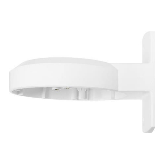
Camera Installation Optional Accessories Mounting Accessories Wall Mount 156.9 x 133.8 x 110.0 mm (6.2 x 5.3 x 4.3 inches); 136.6 g (0.30 lbs). Supplied with Plastic Screw Anchor x 2, M4x25 Self-tapping Screw x 2, M4x7 Mechanical Screw x 2. - Page 4 Pendant Cap Ø 168.0 x 145.0 mm (Ø 6.6 x 5.7 inches); 351.5 g (0.78 lbs). Supplied with Adaptor, Spring Washer-8 x 1, Pendant Tube Washer-8 x 1, Rubber Washer-8 x 1, M8x16 Hex Head Stainless Steel Screw x 1, M4x19 Mechanical Screw x 2, O-Ring x 1.
- Page 5 In-Ceiling Mount Ø 189.0 x 75.9 mm (Ø 7.4 x 3.0 inches); 461.9 g (1.02 lbs). Supplied with Ceiling Sticker, M3x18 Mechanical Screw x 2, Trim Ring. 4S Electrical Box Mount Ø 149.9 x 6.6 mm (Ø 5.9 x 0.3 inches); 68.9 g (0.15 lbs). Supplied with Adaptor, M4x 16.5 Mechanical Screw x 2.
-
Page 6: Wall Mount Installation
Wall Mount Installation IR Fisheye Camera can be installed to the wall with a wall mount bracket. The following lists the required items and tools for installing the camera to the mount kit. Wall Mount Bracket Package Content: Wall Mount Bracket ... - Page 7 Step 2: On the wall, mark the position of the two screw holes (figure 1). Then, draw a line on the top edge of the wall mount bracket (figure 2). figure 1 figure 2 Step 3: Take off the bracket, and draw a 20mm x 30mm rectangle 45mm below the marked line on the wall for cable entry hole.
- Page 8 Step 5: Thread the Ethernet cable through the cable entry hole on the wall and the bracket. If there are other cables, such as power cable, alarm I/O cable and audio I/O cable, also thread them through the hole and the bracket.
- Page 9 Step 9: Match the marked screw holes of the camera housing (figure 1) and the wall mount bracket. Fasten the camera housing to the marked screw holes of the wall mount bracket (figure 2) with the supplied M4x7 mechanical screws. figure 1 figure 2 Step 10:...
-
Page 10: Pendant Cap Installation
Pendant Cap Installation IR Fisheye Camera can be installed to the standard / compact pendant mount with a pendant cap. There are various types of mounting accessories, thus instructions for installing mounting accessories will not be provided here. Before starting the installation, please first fix the mounting accessory to the chosen place. - Page 11 Follow the steps below to install the camera with a Standard / Compact Pendant Mount. Step 1: Run the Ethernet cable through the Pendant Mount. If there are other cables, such as power cable, alarm I/O cable or audio I/O cable, please also insert them through the Pendant.
- Page 12 Step 4: Fasten the Adaptor to the Pendant Cap, and make sure the screw holes are aligned. Step 5: Insert the spring washer-8 followed by the pendant tube washer and the rubber washer-8 to the supplied M8x16 hex head stainless steel screw (figure 1). Then, fix the Adaptor to the Pendant Cap with this hex head screw (figure 2).
- Page 13 Step 6: Coat the PTFE thread seal tape (not supplied) to the thread of the adapter around five times for waterproof purpose. Step 7: Thread the Ethernet cable and other cables through the Pendant Cap. Then, fix the Pendant Cap to the Pendant Mount. Step 8: Loosen the two security screws indicated in the right figure with the supplied security...
- Page 14 Step 10: Align the screw holes on the camera and the Pendant Cap. Then, fasten the camera to the Pendant Cap with the supplied M4x8 mechanical screws. Step 11: Attach the dome cover to the camera and tighten the two security screws. The Pendant Cap installation is completed.
-
Page 15: In-Ceiling Mount Installation
In-Ceiling Mount Installation IR Fisheye Camera can be mounted with the optional accessory: In-Ceiling Mount. The items and tools needed for in-ceiling installation are listed as follows. In-Ceiling Mount Package Content: In-Ceiling Mount (U-shaped Bracket + T-bar Bracket) Ceiling Sticker ... - Page 16 Follow the steps below to install In-Ceiling Mount. Step 1: Loosen the two security screws indicated in the right figure with the supplied security torx and open the dome cover. Step 2: Align the two marked screw holes on the camera to the U-shaped Bracket.
- Page 17 Step 4: Place the Ceiling Sticker on the ceiling board, and cut the circle part out of the ceiling. Step 5: Put up the T-bar Bracket into the ceiling opening and fix it on the ceiling board by tightening the two screws indicated in the figure clockwise.
- Page 18 Step 7: Align the U-shaped Bracket attached to the camera to the T-bar Bracket on the ceiling board. Step 8: Put the camera into the ceiling opening, and fix the U-shaped Bracket on the T-bar Bracket by tightening the two screws shown in the figure.
- Page 19 Step 11: Tighten the two security screws indicated in the right figure with the supplied security torx to fix the dome cover. Step 12: Fix the Trim Ring to the T-bar Bracket to finish the installation. NOTE: There are two magnets on the back of the Trim Ring.
-
Page 20: Electrical Box Mount Installation
4S Electrical Box Mount Installation IR Fisheye Camera can be installed to a 4S electrical box with the adaptor (C-BA1-00). This adaptor provides two types of screw holes (marked as “A” and “B”) for fixing adaptor to the 4S electrical box. Refer to the diagram below for distances between screw holes. - Page 21 Follow the steps below to mount the camera to the 4S electrical box. Step 1: Thread the Ethernet cable through the 4S electrical box. If there are other cables, such as power cable, alarm I/O cable or audio I/O cable, please also insert them through the box.
- Page 22 Step 5: Loosen the two security screws on the dome cover with the supplied security torx and open the cover. Step 6: Run the cables through the conduit entry and connect them to the camera. For alarm I/O and audio I/O connections, please refer to the User’s Manual for further details.
- Page 23 Step 8: Tighten supplied M4x16.5 mechanical screws at the position shown in the right figure to fix the camera to the adaptor. Step 9: Attach the dome cover to the camera and fasten the two security screws. Step10: Installation completed.
Need help?
Do you have a question about the FD360v2 and is the answer not in the manual?
Questions and answers