
Related Manuals for TKH ECO Series


Summary of Contents for TKH ECO Series
- Page 1 sales@artisantg.com artisantg.com (217) 352-9330 | Visit our website - Click HERE...
- Page 2 Manual ECO series eco204, eco267, eco274, eco285, eco414, eco415, eco424, eco445, eco618, eco625, eco655...
-
Page 3: Table Of Contents
GigE IP Setup Connectors GigE Vision 4.1.1 Network (TCP/IP) 4.1.2 XML files Input / output connectors 4.2.1 Hirose™ 12-pin connector layout The ECO The SVCam ECO Series: Extremely small GigE-Vision features Feature description Basic features 6.1.1 Global shutter 6.1.2 Rolling shutter... - Page 4 6.1.3 Exposure 6.1.4 Exposure speed 6.1.5 Acquisition and processing time 6.1.6 Auto exposure 6.1.7 Bit depth 6.1.8 Color 6.1.9 Resolution 6.1.10 Offset 6.1.11 Gain 6.1.12 Binning 6.1.13 Decimation 6.1.14 Burst mode Camera features 6.2.1 Basic capture modes 6.2.2 System clock frequency 6.2.3 Temperature sensor 6.2.4...
- Page 5 List of figures Fig.: 3-1: Camera status LED codes Fig.: 4-1: RJ45 socket connector Fig.: 4-2: Data reduction with jumbo frames Fig.: 4-3: Connecting multiple cameras on multi NICs Fig.: 4-4: Illustration of connecting multiple cameras by a switch Fig.: 4-5: Camera casting to multiple receivers (multicast) Fig.: 6-1: Rolling shutter lines light sensitivity versus time...
- Page 6 List of tables Table: 6-1: Table of dB and corresponding ISO value Table: 10-1:...
-
Page 7: Company Information
Company information SVS-Vistek GmbH Ferdinand-Porsche-Str. 3 82205 Gilching Germany Tel.: +49 (0) 8105 3987-60 Fax: +49 (0) 8105 3987-699 Mail: info@svs-vistek.com Web: https://www.svs-vistek.com Standards This manual is based on the following standards: DIN EN 62079 DIN EN ISO 12100 ISO Guide 37 DIN ISO 3864-2 DIN ISO 3864-4 DIN ISO 16016:2002-5... -
Page 8: Copyright Notice
Copyright notice Forwarding and duplicating of this document, as well as using or revealing its contents are prohibited without written approval. All rights reserved with regard to patent claims or submission of design or utility patent. 1 Company information... -
Page 9: Legal Information
Legal information Errors and omissions excepted. These products are designed for industrial applications only. Cameras from SVS-Vistek are not designed for life support systems where malfunction of the products might result in any risk of personal harm or injury. Customers, integ- rators and end users of SVS-Vistek products might sell these products and agree to do so at their own risk, as SVS-Vistek will not take any liability for any damage from improper use or sale. -
Page 10: Getting Started
Getting started Content of camera set Camera Power supply (if ordered / option) 3D CAD files Manuals Software: GigE-Kit (Win 32bit /64bit & Linux) Power supply Connect the power supply with the Hirose connector. NOTICE This camera does not support hotplugging. >... -
Page 11: Software
Software More information, documents, release notes, latest software and manuals can be downloaded in the SVS-Vistek download area. INFO Depending on your camera model, several software packages apply. 3.4.1 SVCapture 2 SVCapture 2.x is a XML based software tool. It provides the possibility to con- trol a GenICam based camera. - Page 12 3 Getting started...
-
Page 13: Firmware Update
3.4.2 Firmware update Some features may not have been implemented in older software revisions. For updating your camera firmware to the most recent version, you need the firm- ware tool “Firmware Update Tool.exe” and the firmware file (download it from website, login area) matching your camera model. -
Page 14: Gige Ip Setup
3.4.3 GigE IP Setup Your GigEVision camera needs a working network connection. Make sure the camera is attached to the network and is powered on. Make sure everything is plugged in properly and that the firewall settings are not blocking the connection to the camera or SVCapture. -
Page 15: Connectors
Connectors Cameras from SVS-Vistek feature a combined I/O and power supply connector (Hirose) and a data connector. GigE Vision 4.1.1 Network (TCP/IP) Address Assignment By default, the camera does not have a persistent IP address. When forcing an IP address by using the PC internal network dialog, changes are only valid until the next restart of the Camera. -
Page 16: Fig.: 4-3: Connecting Multiple Cameras On Multi Nics
NOTICE Resends result in higher consumption of bandwidths and will lead to drop frames. High quality cables prevent resends. Connecting multiple cameras Multiple GigE cameras can be connected to a PC either via a switch or using dual or quad port network interface connectors (NIC). Fig.: 4-3: Connecting multiple cameras on multi NICs Multiple cameras connected by a switch To connect multiple cameras by a switch, the switch must be managed. -
Page 17: Xml Files
NOTICE Performance might be lost using multiple Cameras on a single port NIC. Multicast When images from a single camera need to be delivered to multiple PCs, mul- ticast (RFC 2236) is used. A switch receives an image data stream from a cam- era and distributes it to multiple destinations in this mode. -
Page 18: Input / Output Connectors
Input / output connectors NOTICE Make sure your external power supply meets specifications. Voltage must not exceed 25 V. 4.2.1 Hirose™ 12-pin connector layout The Hirose connector provides the connectors to power, inputs and outputs. INFO For information about switching lights from inside the camera, refer to "LED strobe control". -
Page 19: The Eco
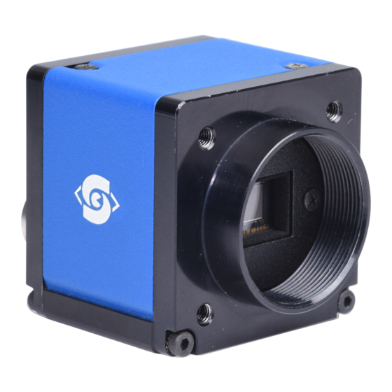
The ECO The SVCam ECO Series: Extremely small A SVCam-ECO fits into any type of application. The SVCam-ECO series impresses with its minimal footprint. And that even without compromising on performance. One of the world’s smallest GigE vision cameras Unparalleled flexibility with an excellent price-performance ratio: This is how one best would describe the SVCam-ECO series. -
Page 20: Feature Description
Feature description This chapter covers features of SVCam cameras. Not every feature might be supported by your specific camera model. For information about the features of your specific model, please refer to the specifications area of our website with your exact model. https://www.svs-vistek.com/en/industrial-cameras/svs-svcam-searchresult.php This chapter covers features of SVCam cameras. -
Page 21: Rolling Shutter
6.1.2 Rolling shutter Rolling shutter is a method of reading out a CMOS sensor, where the whole scene is scanned line after line very rapidly. Despite the speed of scanning the lines one line after the other („rolling“) is very high, it is important to note that the instant of imaging a single line will be different to the point of time of the next line imaging. -
Page 22: Fig.: 6-1: Rolling Shutter Lines Light Sensitivity Versus Time
Light control with rolling shutter As being said, not all sensor lines are sensitive to light at the same time. Make sure your light is ON as long any pixel are going to e exposed. An exo183xGE i.e. needs about 62ms of minimal scanning time. An exo183xCL i.e. needs about 120ms of minimal scanning time. -
Page 23: Exposure
As shown here, after triggering only part of the sensor is sensitive to light (scan- ning time). As soon as scanning time has finished, all pixels are sensitive to light, the sensor is fully open. While being fully open this is the time where flash- ing should happen. -
Page 24: Auto Exposure
Fig.: 6-2: Acquisition and processing time On the other hand, while processing and transferring the image the sensor might capture already the next frame. 6.1.6 Auto exposure Auto Luminance or auto exposure automatically calculates and adjusts exposure time and gain, frame-by-frame. The auto exposure or automatic luminance control of the camera signal is a combination of an automatic adjustment of the camera exposure time (electronic shutter) and the gain. -
Page 25: Bit Depth
6.1.7 Bit depth Values of brightness are internally represented by numbers. The number of bits for brightness representation is limiting the number of color values that can be represented. Bit depth defines the max- imum unique colors or gray levels in an image. bit depth No of gray values = 2 All SVCam models support 8-bit format. -
Page 26: Color
6.1.8 Color Color cameras are identical to the monochrome versions. The color pixels are transferred in sequence from the camera, in the same manner as the mono- chrome, but considered as “raw”-format. Fig.: 6-3: Sensor with Bayer pattern The camera sensor has a color mosaic filter called “Bayer” filter pattern named after the person who invented it. -
Page 27: Resolution
6.1.9 Resolution As mentioned in the specifications, there is a difference between the numerical sensor resolution and the camera resolution. Some pixels towards the borders of the sensor will be used only internally to calibrate sensor values (“Dark pixels”). The amount of dark current in these areas is used to adjust the offset (see "Offset"... -
Page 28: Binning
add 6 dB double ISO value 6 dB 400 ISO 12 dB 800 ISO 18 dB 1600 ISO 24 dB 3200 ISO Table: 6-1: Table of dB and corresponding ISO value NOTICE Gain also amplifies the sensor’s noise. Therefore, gain should be last choice for increasing image brightness. -
Page 29: Decimation
Vertical binning Accumulates vertical pixels. Fig.: 6-6: Vertical binning Horizontal binning Accumulates horizontal pixels. Fig.: 6-7: Horizontal binning 2×2 Binning A combination of horizontal and vertical binning. When DVAL signal is enabled only every third pixel in horizontal direction is grabbed. -
Page 30: Fig.: 6-9: Horizontal Decimation
INFO Refer to "ROI / AOI" on page 39for reducing data rate by reducing the region you are interested in. Fig.: 6-9: Horizontal decimation Fig.: 6-10: Vertical decimation Decimation on color sensors The Bayer pattern color information is preserved with 1/3 horizontal and vertical resolution. -
Page 31: Burst Mode
6.1.14 Burst mode The hardware interface (GigE, USB3, etc.) of your camera may often limit the maximum frame rate of the camera to the maximum frame rate of the interface of the camera. Inside the camera, the sensor speed (internal frame rate) might be higher than the external interface speed (e.g. -
Page 32: Camera Features
Camera features The camera features of the ECO series are defined by the combination of its electronics and firmware features. Firmware features can be upgraded with new firmware releases. 6 Feature description... -
Page 33: Basic Capture Modes
6.2.1 Basic capture modes The camera has 2 basic operation modes. Free run (timed) run: The camera will expose and deliver images on a fixed schedule. Triggered: The camera will wait for an external signal and start exposure after receiving the external trigger signal. -
Page 34: Fig.: 6-13: Basic Capture Modes - Triggered Mode (Pulse Width With Overlap)
Fig.: 6-13: Basic capture modes - triggered mode (pulse width with overlap) Exposure time of the next image can overlap with the frame readout of the cur- rent image (rising edge of trigger pulse occurs when FVAL is high). When this happens: the start of exposure time is synchronized to the falling edge of the LVAL signal. -
Page 35: Fig.: 6-15: Mode 1: External Trigger With Pulse Width Exposure Con
When the rising edge of trigger signal occurs after frame readout has ended (FVAL is low), the start of exposure time is not synchronized to LVAL and expos- ure time starts after a short and persistent delay. Exposure time can be changed during operation. No frame is distorted during switching time. -
Page 36: System Clock Frequency
Fig.: 6-16: Mode 1: External trigger with pulse width exposure control (overlap) Fig.: 6-17: Mode 1: External trigger with programmable exposure time (non-overlap) Fig.: 6-18: Mode 1: External trigger with programmable exposure time (overlap) 6.2.2 System clock frequency Default system clock frequency in almost every SVCam is set to 66.6 MHz. To validate your system frequency refer to: specifications. -
Page 37: Temperature Sensor
INFO Use multiples of 15 ns to write durations into camera memory. 6.2.3 Temperature sensor A temperature sensor is installed on the main board of the camera. To avoid overheating, the temperature is constantly monitored and read. Besides soft- ware monitoring, the camera indicates high temperature by a red flashing LED (see flashing LED codes). -
Page 38: Look-Up Table
6.2.5 Look-up table The look-up table feature (LUT) lets the user define certain values to every bit value that comes from the ADC. To visualize a LUT a curve diagram can be used, similar to the diagrams used in photo editing software. -
Page 39: Fig.: 6-21: Several Gamma Curves Comparable To A Lut
Historically gamma correction was used to correct the illumination behavior of CRT displays, by compensating brightness-to-voltage with a gamma value between 1,8 up to 2,55. The gamma algorithms for correction can simplify resolution shifting as shown seen below. Input & output signal range from 0 to 1 Gamma Output-signal = Input-signal Fig.: 6-21: Several gamma curves comparable to a LUT... -
Page 40: Roi / Aoi
6.2.6 ROI / AOI In partial scan mode or Area-Of-Interest (AOI) mode (or Region-Of-Interest (ROI) mode) only a certain region of the sensor will be read. Fig.: 6-22: AOI on area sensor Selecting an AOI will reduce the number of horizontal lines being read. This will reduce the amount of data to be transferred, thus increasing the maximum speed in terms of frames per second. -
Page 41: Pixel Clock Frequency Selection
has finished. After the read out of image 1 is done, image 2 is transferred and read out. The readout time of each camera is sensor dependent. INFO Contact the SVS-Vistek support team for details on sensor readout timing. During the read out of the 2nd image the camera cannot take images until the next Exsync signal (rising edge) arrives and initiates the next exposure cycle. - Page 42 Set a user set as default Use User Set Default to select the user set that is to be loaded when the camera is started. Save this setting with UserSetSave (In the example below, user set 5 is saved as default). Reset to factory default User sets can be reset to factory settings.
-
Page 43: I/O Features
I/O Features The SVCam cameras are equipped with several inputs and outputs, providing state-of-the-art control regarding input and output channels. All I/O functions are realized as modules. These functions can be connected in the GenICam tree. 6.3.1 GenICam provides a generic programming interface to control all kinds of cameras and devices. - Page 44 NOTICE All modfications in the GenICam tree will have immediate effect. 6 Feature description...
-
Page 45: Specifications
Specifications INFO The camera series specifications and spectral sensitivity characteristics are provided on the web site: https://www.svs-vistek.com/en/industrial-cameras/svs-svcam-search-res- ult.php 7 Specifications... -
Page 46: Dimensions
Dimensions INFO All length units in mm. Find the technical drawings in the web download area at https://www.svs-vistek.com/en/support/svs-support-download-center.php CAD step files available with valid login at SVS-VISTEK.com 8 Dimensions... -
Page 47: Terms Of Warranty
Terms of Warranty 9 Terms of Warranty... - Page 48 Seller warrants that the article to be delivered under this Standard order will be free from defects in material and work- Products War- manship under normal use and service for a period of 2 ranty and years from date of shipment. The liability of Seller under Adjustment this warranty is limited solely to replacing or repairing or issuing credit (at the discretion of Seller) for such...
- Page 49 function 9 Terms of Warranty...
-
Page 50: Faq
Problem Solution Camera does not Check if camera is set to “Mode 0“. I.e. free running respond to light. with programmed exposure ctrl. When done, check with the program “Convenient Cam“ if you can read back any data from the camera, such as “Mode“, “type“... -
Page 51: Glossary Of Terms
Glossary of terms Aberration Spherical aberration occurs when light rays enter near the edge of the lens; Chromatic aberration is caused by dif- ferent refractive indexes of different wavelengths of the light. (Blue is more refractive than red) Analogue-to-Digital Converter, also known as A/D con- verter Aperture In optics, Aperture defines a hole or an opening through... - Page 52 between two values of a physical quantity. Decimation For reducing width or height of an image, decimation can be used (CMOS sensors only). Columns or rows can be ignored. Image readout time is thereby reduced. Defect map Identifies the location of defect pixels unique for every sensor.
-
Page 53: Trol (Non-Overlap)
Multicast Multicast (one-to-many or many-to-many distribution) is an ethernet group communication where information is addressed to a group of destination computers sim- ultaneously. Multicast should not be confused with phys- ical layer point-to-multipoint communication. Pulse width modulation. Keeping voltage at the same level while limiting current flow by switcheing on an off at a very high frequency. - Page 54 CCD sensors can occur divided into two, four or more regions to double/quadruple the read out time. TCP/IP TCP/IP provides end-to-end connectivity specifying how data should be packetized, addressed, transmitted, routed and received at the destination. USB3 Vision The USB3 Vision interface is based on the standard USB 3.0 interface and uses USB 3.0 ports.
Need help?
Do you have a question about the ECO Series and is the answer not in the manual?
Questions and answers