Table of Contents
Advertisement
Quick Links
Advertisement
Table of Contents

Related Manuals for TKH SVS-Vistek SHR411


Summary of Contents for TKH SVS-Vistek SHR411
- Page 1 Manual SHR 10GigE shr411, shr461, shr661...
-
Page 2: Table Of Contents
Content Company information Standards Disclaimer Copyright notice Legal information USA and Canada Europe The SHR series High precision with large pixels 10 GigE Vision 2.4.1 Speed is king 2.4.2 Optimized network adapter tuning 4I/O adds light and functionality Getting started Get help Find camera specs Power supply... - Page 3 GigE Vision 4.2.1 Network (TCP/IP) 4.2.2 XML files 10GigE limitations and issues 4.3.1 Compatibility to nBase-T 4.3.2 Bandwidth limitation 4.3.3 Recommended setup Hirose I/O connector Feature description Basic features 5.1.1 Gain 5.1.2 Resolution 5.1.3 Offset 5.1.4 Color 5.1.5 Flip image 5.1.6 Binning 5.1.7...
- Page 4 5.3.2 Assigning I/O Lines – IOMUX 5.3.3 5.3.4 LED strobe control 5.3.5 Sequencer 5.3.6 Optical input 5.3.7 PLC / Logical operation on inputs 5.3.8 Serial data interfaces 5.3.9 Trigger-edge sensitivity 5.3.10 Debouncing trigger signals 5.3.11 Prescale Dimensions M72 Mount shr411XGE shr461XGE shr661XGE Appendix...
-
Page 5: Company Information
Company information SVS-Vistek GmbH Ferdinand-Porsche-Str. 3 82205 Gilching Germany Tel.: +49 8105 3987-60 Fax: +49 8105 3987-699 Mail: info@svs-vistek.com Web: https://www.svs-vistek.com Standards This manual is based on the following standards: DIN EN 62079 DIN EN ISO 12100 ISO Guide 37 ... -
Page 6: Copyright Notice
Copyright notice Forwarding and duplicating of this document, as well as using or revealing its con- tents are prohibited without written approval. All rights reserved with regard to patent claims or submission of design or utility patent. 1 Company information... -
Page 7: Legal Information
Legal information Errors and omissions excepted. These products are designed for industrial applications only. Cameras from SVS- Vistek are not designed for life support systems where malfunction of the products might result in any risk of personal harm or injury. Customers, integrators and end users of SVS-Vistek products might sell these products and agree to do so at their own risk, as SVS-Vistek will not take any liability for any damage from improper use or sale. -
Page 8: The Shr Series
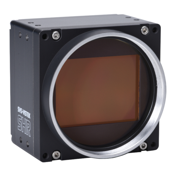
The SHR series High precision with large pixels The SVCam SHR series is a series of industrial machine vision cameras featuring espe- cially on very high image resolutions with large pixels and global shutter. In the indus- trial machine vision business, there are applications where global shutter with high resolutions cannot permit compromises on image quality. -
Page 9: O Adds Light And Functionality
INFO All known 10GigE interface cards require Windows 10 as minimum version. Latest Linux versions are supported as well. 4I/O adds light and functionality Fig.: 2-1: Illustration of 4I/O concept of switching LEDs Your SVS-Vistek camera is equipped with the innovative 4I/O-interface allowing full light control, replacing external strobe controllers. -
Page 10: Getting Started
Getting started Get help In case of issues with the camera we are happy to help. For being able to help you in a fast and efficient way, we ask you for a description of the issues using camera in your support request. -
Page 11: Connect The Camera
3.3.2 Connect the camera The camera is powered on by connecting power to to the camera. Connect the power supply with the Hirose connector. When using your own power supply (voltage range 10 -25 V DC) see also Hirose™ 12-Pin layout of the power connector. For power input specifications refer to specifications. -
Page 12: Camera Status Led Codes
Camera status LED codes On power up, the camera will indicate its current operation status with a flashing LED on its back. The LED will change color and rhythm. The meaning of the blinking codes translates as follows: Fig.: 3-1: Camera status LED codes Software and firmware Further information, documentations, release notes, latest software and application manuals can be downloaded in the download area on SVS-Vistek... - Page 13 Fig.: 3-2: Screenshot of SVCapture 2.x: GenICam tree and current image Setup of SVCapture2 Installation procedure may differ from PC to PC. It is recommended to install the whole software package. For this step it is necessary to have root access to your com- puter.
- Page 14 3. Choose destination folder and select necessary modules / drivers. The TLxxx modules are the GenTL drivers, necessary as well if you want to use SVS-Vistek driver with third party software. 4. In case of system warnings regarding modification of USB3 drivers or GigE/10GigE filter drivers: The specified performance is possible only with these highly optimized drivers.
- Page 15 2. Start SVCapture. SVCapture will try to discover your camera. 3. Click on the camera being found and you’re connected. Depending on your interface type, with TL Settings you are able to adjust which inter- face types should be included in the camera discover process. NOTICE If you have installed third-party GenTL drivers (e.g.
-
Page 16: Software Development Kit
4. Find and adjust your camera features in the GenICam tree. Click and adjust items by number (1.) or slider (2.) and start grabbing images from the camera. You can find the USB 3.0 driver which has been installed automatically within the hardware manager: 3.5.2 Software development kit... -
Page 17: Firmware Update
C:\Program Files\SVS-VISTEK GmbH\SVCam Kit\SDK INFO Refer to the “Getting started with SDK” manual for first steps in programming your SVS-Vistek camera. This document should be included in the docs section of your installation. The following platforms are supported: X86 (Windows, Linux, MacOS support on request) ... - Page 18 3 Getting started...
-
Page 19: Connectors
Connectors Cameras from SVS-Vistek feature a combined I/O and power supply connector (Hirose) and a data connector. GigE IP Setup Your GigEVision camera needs a working network connection. Make sure the cam- era is attached to the network and is powered on. Make sure everything is plugged in properly and that the firewall settings are not blocking the connection to the camera or SVCapture. - Page 20 Manual IP configuration will permit you to Assign a new IP address (make sure the new address is unique and valid in the current subnet) Save a specific address as a permanent address to the camera (Persistent) ...
-
Page 21: Gige Vision
GigE Vision 4.2.1 Network (TCP/IP) Address Assignment By default, the camera does not have a persistent IP address. When forcing an IP address by using the PC internal network dialog, changes are only valid until the next restart of the Camera. For a peer-to-peer connection of a GigE camera to a PC a network address assign- ment based on LLA (Local Link Address) is recommended. - Page 22 Fig.: 4-3: Connecting multiple cameras on multi NICs Multiple cameras connected by a switch To connect multiple cameras by a switch, the switch must be managed. It might also be necessary to operate the cameras in an “inter packet delay” applying a smother image data stream.
-
Page 23: Xml Files
Multicast When images from a single camera need to be delivered to multiple PCs, multicast (RFC 2236) is used. A switch receives an image data stream from a camera and dis- tributes it to multiple destinations in this mode. Since a GigE camera always needs a single controlling application, there will be only one master application. -
Page 24: Recommended Setup
Special NICs support 100% connections without frame drops. 4.3.3 Recommended setup It is recommended to use a 10GigE Ethernet card with grabber capabilities. All SVS- Vistek certification setups are using this kind of cards. Contact sales@svs-vistek.com for details and more recommendations. ... -
Page 25: Feature Description
Feature description This chapter covers features of SVCam cameras. Not every feature might be sup- ported by your specific camera model. For information about the features of your spe- cific model, please refer to the specifications area of our website with your exact model. -
Page 26: Resolution
Auto gain For automatic adjustment of gain refer to auto exposure (see "Auto exposure" on page 42). When using auto-gain with steps of gain the noncontinuous gain adjustment might be visible in final image. Depending on your application it might be preferable to use fixed gain values instead and modify exposure with exposure time. -
Page 27: Color
5.1.4 Color Color cameras are identical to the monochrome versions. The color pixels are trans- ferred in sequence from the camera, in the same manner as the monochrome, but considered as “raw”-format. Fig.: 5-3: Sensor with Bayer pattern The camera sensor has a color mosaic filter called “Bayer” filter pattern named after the person who invented it. -
Page 28: Flip Image
5.1.5 Flip image Images can be mirrored horizontally or vertically. Image flip is done inside the memory of the camera, therefore not increasing the CPU load of the PC. Fig.: 5-4: Original image Fig.: 5-5: Horizontal flip 5 Feature description... -
Page 29: Binning
Fig.: 5-6: Vertical flip 5.1.6 Binning Binning provides a way to enhance dynamic range, but at the cost of lower res- olution. Binning combines electron charges from neighboring pixels directly on the chip, before readout. Binning is only used with monochrome CCD Sensors. For reducing resolution on color sensors refer to "Decimation"... -
Page 30: Decimation
Horizontal binning Accumulates horizontal pixels. Fig.: 5-8: Horizontal binning 2×2 Binning A combination of horizontal and vertical binning. When DVAL signal is enabled only every third pixel in horizontal direction is grabbed. Fig.: 5-9: 2x2 binning 5.1.7 Decimation For reducing width or height of an image, decimation can be used. Columns or rows can be ignored. - Page 31 Fig.: 5-10: Horizontal decimation Fig.: 5-11: Vertical decimation Decimation on color sensors The Bayer pattern color information is preserved with 1/3 horizontal and vertical res- olution. The frame readout speed increases approx. by factor 2.5. Fig.: 5-12: Decimation on color sensors 5 Feature description...
-
Page 32: Genicam
5.1.8 GenICam provides a generic programming interface to control all kinds of cameras and devices. Regardless of the interface technology (GigE Vision, USB3 Vision, CoaXPress, Camera Link, etc.) or implemented feature, the application pro- gramming interface (API) will always be the same. The SNFC makes sure the feature names are similar throughout the manufacturers, making it more easy to switch cam- era models. -
Page 33: Trigger Modes
5.1.9 Trigger modes To start capturing images, the camera has to receive a trigger signal. This trigger sig- nal can be a software trigger, it might be an electric signal on the hardware I/O or it can be a timed trigger (sequence of images or "Precision Time Protocol"). - Page 34 Exposure time can be changed during operation. No frame is distorted during switch- ing time. If the configuration is saved to the EEPROM, the set exposure time will remain also when power is removed. Details of external trigger mode Diagrams below are equivalent for CCD and CMOS technique. 5 Feature description...
-
Page 35: Shutter Modes
5.1.10 Shutter modes CCD and CMOS area cameras consist of pixels, ordered in lines and columns. All pixel are exposed to light and then read out to camera electronics. There is a dif- ference of reading out the sensor between global and rolling shutter. Especially flash- ing and moving objects might need more attention with rolling shutter. - Page 36 Rolling shutter mode Pixel reset line by line Line by line light integration Integration starts with different point of time for each line All lines stop integration at different time Line readout immediately after line exposure ...
- Page 37 Flash strobe on whole exposure time - or - Flash strobe only while all lines are sensitive to light at the same time (delay flash strobe until all lines are sensitive to light) Make sure to protect from changing environment light (recommendation: flash strobe in darkness).
- Page 38 Fig.: 5-14: Rolling shutter lines light sensitivity versus time As shown here, after triggering only part of the sensor is sensitive to light (scanning time). As soon as scanning time has finished, all pixels are sensitive to light, the sensor is fully open. While being fully open this is the time where flashing should hap- pen.
- Page 39 Frame rate calculation with exo183 with rolling shutter lines 3672 dummy lines total lines 3726 readout time 1x3_1Y 22,2 µs * 3726 = 82717,2 µs exp delay 300 µs frame readout time 83017,2 µs This is minimum time for camera readout with 0s exposure time.
- Page 40 Benefits All pixel reset all lines same time Light integration starts with same point of time for each line All lines stop integration at different time Readout line by line Limitations ROI limitations apply similar to rolling shutter. ...
-
Page 41: Exposure
In Global Reset Mode flash is starting together with exposure, all CMOS lines are sensitive to light. Flash time has to be shorter than exposure time. Exposure time is determined by flash time. INFO Strobe control jitter might be visible in the image as structures or as brightness instabilities. -
Page 42: Auto Exposure
5.1.13 Auto exposure Auto Luminance or auto exposure automatically calculates and adjusts exposure time and gain, frame-by-frame. The auto exposure or automatic luminance control of the camera signal is a com- bination of an automatic adjustment of the camera exposure time (electronic shutter) and the gain. -
Page 43: Bit Depth
5.1.15 Bit depth Values of brightness are internally represented by numbers. The number of bits for brightness representation is limiting the number of color values that can be rep- resented. Bit depth defines the maximum unique colors or gray levels in an image. bit depth No of gray values = 2 All SVCam models support 8-bit format. -
Page 44: Roi / Aoi
5.1.16 ROI / AOI In partial scan mode or Area-Of-Interest (AOI) mode (or Region-Of-Interest (ROI) mode) only a certain region of the sensor will be read. Fig.: 5-18: AOI on area sensor Selecting an AOI will reduce the number of horizontal lines being read. This will reduce the amount of data to be transferred, thus increasing the maximum speed in terms of frames per second. - Page 45 This shading can be caused by non-uniform illumination, non-uniform camera sens- itivity, vignetting of the lens, or even dirt and dust on glass surfaces (lens). Shading correction is a procedure to create a flatfield image out of a non-uniform image regardless of the reasons of the non-uniformity. Before doing shading cor- rection, make sure your lens is clean and in perfect condition.
- Page 46 How it works The tool will divide the image into squares of 16x16 pixel. Out of every 16x16 pixel cluster a set of shading values consisting of specific gain and offset per cluster is cal- culated. The resulting map can be uploaded into the camera and will compensate for any shading, lens-based or based on illumination.
- Page 47 2. With SVCapture load these reference images. 3. See shading in the preview 4. Generate the shading map 5. Save map to disk. This file can be used in programmed environments via SDK as well. 6. Upload it to the camera and see the result. If lighting did not change from start of procedure, you should see a uniform image with enabled shading control.
-
Page 48: Defect Pixel Correction
7. Run camera with same lighting to see corrected image. 5.2.3 Defect pixel correction All image sensor have defect pixels in a lesser or greater extent. Type and number of defects determine the quality grade (quality classification) of the sensor. Defect Pixel Correction is using information from neighboring pixels to compensate for defect pixels or defect pixel clusters (cluster may have up to five defect pixels). - Page 49 Fig.: 5-20: Illustration of a defect pixel Procedure of pixel correction SVCapture is the tool to generate pixel correction maps. The pixel correction assistant provides everything to create, load, enable and restore defect pixel creation maps. Defect pixel correction is possible with certain models only. See camera specs whether your model does support this.
- Page 50 The procedure to create a std map is pretty straight forward. Befrore starting gen- erating the map, in the GenICam tree do following: Set gain to 0 dB Disable autogain Set offset to 0 Record a set of dark images (put lens cap on) Defect pixel map generation SVCapture defect pixel assistant requires a set of images being loaded ...
- Page 51 Procedure of pixel correction SVCapture is the tool to generate pixel correction maps. The pixel correction assistant provides everything to create, load, enable and restore defect pixel creation maps. Defect pixel correction is possible with certain models only. See camera specs whether your model does support this.
-
Page 52: Look-Up Table
5.2.4 Look-up table The look-up table feature (LUT) lets the user define certain values to every bit value that comes from the ADC. To visualize a LUT a curve diagram can be used, similar to the diagrams used in photo editing software. The shown custom curve indicates a contrast increase by applying an S-shaped curve. -
Page 53: Roi / Aoi
The gamma algorithms for correction can simplify resolution shifting as shown seen below. Input & output signal range from 0 to 1 Gamma Output-signal = Input-signal Fig.: 5-22: Several gamma curves comparable to a LUT Gamma values less than 1.0 map darker image values into a wider ranger. ... -
Page 54: Basic Capture Modes
Fig.: 5-23: AOI on area sensor Selecting an AOI will reduce the number of horizontal lines being read. This will reduce the amount of data to be transferred, thus increasing the maximum speed in terms of frames per second. With CCD sensors, setting an AOI on the left or right side does not affect the frame rate, as lines must be read out completely. - Page 55 Fig.: 5-25: Basic capture modes - triggered mode (pulse width with overlap) Exposure time of the next image can overlap with the frame readout of the current image (rising edge of trigger pulse occurs when FVAL is high). When this happens: the start of exposure time is synchronized to the falling edge of the LVAL signal.
-
Page 56: Trigger Modes
5.2.7 Trigger modes To start capturing images, the camera has to receive a trigger signal. This trigger sig- nal can be a software trigger, it might be an electric signal on the hardware I/O or it can be a timed trigger (sequence of images or "Precision Time Protocol"). - Page 57 Details of external trigger mode Diagrams below are equivalent for CCD and CMOS technique. 5 Feature description...
-
Page 58: Read-Out Control
5.2.8 Read-out control Read-out control defines a delay between exposure and data transfer. Read-out con- trol is used to program a delay value (time) for the readout from the sensor. With more than one camera connected to a single computer, image acquisition and rendering can cause conflicts for data transfer, on CPU or bus system. -
Page 59: Predefined Configurations (User Sets)
5.2.11 Predefined configurations (user sets) The camera starts with default values for all features when turned on. Settings made during operation will expire when the camera is turned off. All preset adjustments are located in the GenICam tree in the “User Set Control” property. -
Page 60: I/O Features
Afterwards this factory default user set must be saved again as user set (in the example below, user set 2 is overwritten with the factory settings). I/O Features The SVCam cameras are equipped with several inputs and outputs, providing state- of-the-art control regarding input and output channels. -
Page 61: Assigning I/O Lines - Iomux
NOTICE All modfications in the GenICam tree will have immediate effect. 5.3.2 Assigning I/O Lines – IOMUX The IOMUX is best described as a switch matrix. It connects inputs, and outputs with the various functions of SVCam I/O. It also allows combining inputs with Boolean arguments. - Page 62 LineSelector Translation Line7 Sequencer Line8 Debouncer Line9 Prescaler Line10 Input0 Line11 Input1 Line12 Input2 Line13 Input3 Line14 Input4 Line15 LogicA Line16 LogicB Line17 LensTXD Line18 Pulse0 Line19 Pulse1 Line20 Pulse2 Line21 Pulse3 Line22 Uart2 In The input and output lines for Strobe and Trigger impulses can be arbitrarily assigned to actual data lines.
- Page 63 Input vector to switch matrix Name Description io_in(0) trigger input 0 – 24 Volt / RS-232 / opto * io_in(1) trigger input 0 – 24 Volt / RS-232 / opto * io_in(2) trigger input 0 – 24 Volt / RS-232 / opto * io_in(3) trigger input 0 –...
- Page 64 Output vector from switch matrix Name / register Description io_out(0) output open drain io_out(1) output open drain io_out(2) output open drain * io_out(3) output open drain * io_txd output, when debug='0' rxd_to_uart1 output (uart_in) trigger output sequenzer_hw_trigger input to module iomux_sequenzer_0 debounce input input to module iomux_dfilter_0 prescale input...
- Page 65 Example of an IOMUX configuration Fig.: 5-29: Example of an IOMUX configuration The trigger signal comes in on line 0 Debounce it. connect line 0 to 8: 1000000000000000000000000 signal appears again on line 15 – debouncer out Use the prescaler to act only on every second pulse.
- Page 66 Inverter The inverter enabled at a certain line provides the reverse signal to or from a module. Set to “1” With set to “1” enabled in a certain line, this line will provide a high signal no matter what signal was connected to the line before. Set to “1”...
-
Page 67: Pwm
5.3.3 During Pulse Width Modulation (PWM), a duty cycle is modulated by a fixed fre- quency square wave. This describes the ratio of ON to OFF as duty factor or duty ratio. Why PWM? Pulse width modulation is an extremely efficient way (in terms of power dissipation) to provide/regulate electrical power to consumers as long as they do not need unin- terrupted supply (such as diodes or LEDs). - Page 68 Examples of PWMs The integrals over both periods are equal. An equal amount of Photons will be emitted. The intensity of light is the same. The periods are equal in length. Fig.: 5-31: Example: 25% PWM load Fig.: 5-32: Example: 50% PWM load Fig.: 5-33: Example: 75% PWM load 5 Feature description...
-
Page 69: Led Strobe Control
The PWM module Fig.: 5-34: The PWM module 5.3.4 LED strobe control The SVCam 4I/O concept contains an integrated strobe controller. Its controls are integrated into the GenICam tree. With LED lights attached to the outputs, this enables the user to control the light without external devices. Being controlled via GenICam, any GenICam-compliant 3 party software is able to control the light as well. - Page 70 LEDs in continuous mode Voltage drop al 5 LEDs, 2,2V per LED (see spec. of LED) 11 V Max. continuous current (see spec. of LED) 250 mA Voltage supply 24 V Voltage drop at resistor (24 V – 11 V) 13 V 52 Ω...
-
Page 71: Sequencer
Strobe duration The exposure time of LED lights can be set in tics. The min duration is 1 µs. The longest time is 1 second. Strobe delay The delay between the (logical) positive edge of trigger pulse and strobe pulse out- put. - Page 72 Camera wiring 3 LED lights are physically connected to the camera on out 0-2 (red, green, blue) Out 3 is not used I/O matrix 4 images to be taken (RGBW) result in 4 sequences RGB PWM change with different intensities (duty cycle) taking care for dif- ferences in spectral response of the camera sensor ...
- Page 73 Values to set in GenICam prop- Interval 1 erties Interval 0 (RED) (GREEN) Interval 2 (BLUE) Interval 3 (WHITE) Sequencer Interval 66666667 tic 66666667 tic 66666667 tic 66666667 tic (1000 ms) (1000 ms) (1000 ms) (1000 ms) 0 tic 0 tic 6666667 tic 0 tic Seq pulse A start...
- Page 74 Sequencer setup with SVCapture Starting with SVCapture 2.5.2, there is a sequencer assistant, providing easy setup of the sequencer settings. The assistant will help you to setup timings for start exposure and lighting and so on. The PWMs are connected to the physical outputs (e.g. for driv- ing LED lights)..
- Page 75 Feature name Feature value Acquisition Control - Continuous Acquisition Mode Acquisition Control – Trigger Selector - Trig- ger Mode Acquisition Control – Line 1 Trigger Selector - Trig- ger Source Acquisition Control – Trigger Selector – Trigger Width Exposure Mode Enhanced IO –...
-
Page 76: Optical Input
5.3.6 Optical input In many trigger signals you find noise, transients and voltage spikes. These are able to damage components in the camera and trigger signal interpretation might be dif- ficult. An optical input separates the electrical trigger and camera circuits. The benefit of such an optical input is to avoid all these kinds of interaction from power sources or switches. - Page 77 Do it in the GenICam tree The logic function always combines the values of Digital IO InputA/LogicA and InputB/LogicB. In case of the Trigger enable logic function, LogicB is the trigger enable signal and will be combined with LogicA value. NAND XNOR A B Y...
-
Page 78: Serial Data Interfaces
5.3.8 Serial data interfaces (ANSI EIA/) TIA-232-F RS-232 and RS-422 (from EIA, read as Radio Sector or commonly as Recommended Standard) are technical standards to specify electrical characteristics of digital sig- naling circuits. Serial connection might be used to control SVCams. These signals are used to send low-power data signals to control exposure, light or lenses (MFT). -
Page 79: Trigger-Edge Sensitivity
5.3.9 Trigger-edge sensitivity Trigger-edge sensitivity is implemented by a “Schmitt trigger”. Instead of triggering to a certain value, the Schmitt trigger provides a threshold. Fig.: 5-39: Schmitt trigger noise suppression 5 Feature description... -
Page 80: Debouncing Trigger Signals
5.3.10 Debouncing trigger signals Bounces or glitches caused by a switch can be avoided by software within the SVCam. Fig.: 5-40: Bounces or glitches caused by a switch Therefore the signal will not be accepted until it lasts at least a certain time. ... - Page 81 Input 1 debounce time here is about 1ms. The debouncer module Fig.: 5-42: The debouncer module 5 Feature description...
-
Page 82: Prescale
5.3.11 Prescale The Prescale function can be used for masking off input pulses by applying a divisor with a 4-bit word, resulting in 16 unique settings. Reducing count of interpreted trigger signal Use the prescale function to ignore a certain count of trigger signals. ... -
Page 83: Dimensions
Dimensions INFO All length units in mm. Find the technical drawings in the web download area at https://www.svs-vistek.com/en/support/svs-support-download-center.php CAD step files available with valid login at SVS-VISTEK.com M72 Mount Diameter 72 mm Mechanical sensor flange distance 19.90mm With cover glas the calculated optical sensor flange distance shrinks down to 19.57 mm Fig.: 6-1: M72-mount... -
Page 84: Shr411Xge
shr411XGE 6 Dimensions... - Page 85 6 Dimensions...
- Page 86 6 Dimensions...
-
Page 87: Shr461Xge
shr461XGE 6 Dimensions... - Page 88 6 Dimensions...
- Page 89 6 Dimensions...
-
Page 90: Shr661Xge
shr661XGE 6 Dimensions... - Page 91 6 Dimensions...
- Page 92 6 Dimensions...
-
Page 93: Appendix
Appendix I/O driver circuit schematics Camera power supply and power supply for PWM out is 25V max. Power for PWM out has to be supplied via Hirose connector. The open drain outputs are ledged to ground, that means you connect your LED on the positive side to your (light-)power source, the negative LED connector goes to the camera out.
Need help?
Do you have a question about the SVS-Vistek SHR411 and is the answer not in the manual?
Questions and answers