
Subscribe to Our Youtube Channel
Summary of Contents for Amsco RELIANCE 444
- Page 1 UNCRATING/INSTALLATION INSTRUCTIONS ® ® AMSCO RELIANCE Load/Unload Modules (07/15/99) P-122994-142 Rev. 6...
- Page 2 LIMITATIONS OF LIABILITY AND INDEMNITY IN NO CASE, WHETHER AS A RESULT OF A BREACH OF CONTRACT, BREACH OF WAR- RANTY OR TORT (INCLUDING STERIS'S OR CUSTOMER'S WILLFUL ACTS OR NEGLIGENCE OR STRICT LIABILITY) SHALL STERIS OR CUSTOMER BE LIABLE TO THE OTHER FOR ANY CONSEQUENTIAL OR INCIDENTAL DAMAGES INCURRED BY THE OTHER, INCLUDING, BUT NOT LIMITED TO, LOSS OF REVENUE, PROFITS OR GOODWILL.
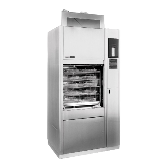
- Page 3 Reliance 444 Load/Unload Modules, when connected to Indications For Use the Amsco Reliance 444 Single Chamber Washer/Disinfector, pro- vide a fully automated rack conveyance system. Load/Unload modules are available in one rack and two rack configurations. Check the Occupational Health and Safety Act, as well as local...
-
Page 4: Table Of Contents
TABLE OF CONTENTS SECTION TITLE PAGE LISTING OF WARNINGS, CAUTIONS AND ... SYMBOLS ............1-1 Warnings and Cautions ........... 1-1 Symbols ................1-2 UNCRATING INSTRUCTIONS ......2-1 Open Cartons ..............2-1 Remove Wooden Bases and Move Conveyor Modules .. 2-2 INSTALLATION INSTRUCTIONS ..... - Page 5 Hardware Box Contents ..........2-2 Jumper Setting .............. 3-11 FIGURE TITLE PAGE Reliance 444 Load and Unload Modules ......2-1 Washer Cold Water Connections ........3-2 Washer Cold Water Connections Modified for Load/Unload Modules ..........3-3 Cold Water and Drain Connections ......... 3-4 Electrical Connections .............
-
Page 6: Listing Of Warnings, Cautions And ........... Symbols
LISTING OF WARNINGS, CAUTIONS AND SYMBOLS The following is a listing of the safety precautions which must be observed when uncrating and installing this equipment. WARNINGS indicate the potential for danger to personnel and CAUTIONS indicate the potential for damage to equipment. These precautions are repeated (in whole or in part), where applicable, throughout the instructions. -
Page 7: Symbols
Symbols Symbol Definition Transfer of Heat, Hot Surface Protective Earth (Ground) Warning! Risk of Electrical Shock Electrostatic Sensitive Device Attention, Consult Manual for Further Instructions Tip N’ Tell This Side Up Keep Dry Fragile Do Not Stack Amperage Rating of the Unit Voltage Rating of the Unit Alternating Current Power Rating of the Unit... -
Page 8: Uncrating Instructions
Emergency Stop Emergency Stop Service Panel Button Button Load-End (C2) Unload-End (C3) Conveyor Module Conveyor Module Conveyor Side Spray Head Optional Two Rack Module Service Panel Compartments Figure 2-1. Reliance 444 Load and Unload Modules 122994-142 Uncrating Installation Instructions Uncrating Instructions... -
Page 9: Remove Wooden Bases And Move Conveyor Modules
ARD: When removing bolts, wear NOTE: Make sure equipment is placed in the following order: Load- gloves to protect your hands. end conveyor module, Amsco Reliance 444 Single Chamber Washer/ Disinfector, Unload-end conveyor module. WARNING - PERSONAL INJURY AND/OR EQUIPMENT DAMAGE 6. -
Page 10: Installation Instructions
INSTALLATION INSTRUCTIONS 1. Install the Amsco ® Reliance ® 444 Single Chamber Washer/ Before Installing Disinfector according to the Uncrating/Installation Instructions, Equipment P-122992-165, provided with the washer. IMPORTANT: Make sure to review washer Installation Checklist before installing Load/Unload modules. WARNING - PERSONAL INJURY... -
Page 11: Washer Cold Water Connections
Cold Water Inlet to Condenser Piping Figure 3-1. Washer Cold Water Connections 122994-142 Uncrating/Installation Instructions Installation Instructions... -
Page 12: Washer Cold Water Connections Modified
Condenser Cold Water Supply Piping Insert Plug if Washer is not Equipped with Condenser Replacement Cold Water Supply Piping Figure 3-2. Washer Cold Water Connections Modified for Load/Unload Modules Uncrating/Installation Instructions 122994-142 Installation Instructions... -
Page 13: Cold Water And Drain Connections
5. Install CW1 tee at the end of the cold water supply piping (see Figure 3-2). 6. Connect other end of tee to condenser cold water supply piping (see Figure 3-2). NOTE: If washer is not equipped with condenser, install cold water supply piping as shown in Figure 3-2, except insert a 1/2"... -
Page 14: P54 Cable Replacement
NOTE: Check underneath washer main console for the part number P54 Cable Replacement for the P54 AC Wiring Harness. If part number is 117-906-552 and washer is steam heated, there is no cable to replace. If washer is electric heated built before 3603298XXX (electric heaters in wash chamber), P54 cable must be replaced. -
Page 15: Electrical Connections
Figure 3-4. Electrical Connections 122994-142 Uncrating/Installation Instructions Installation Instructions... -
Page 16: Installation Of Door Proximity Sensor
1. Locate door sensor holders on top of washer (see Figure 3-4). Installation of Door Each holder has one empty space to accommodate new sen- sors. Proximity Sensor 2. Install Door Open proximity sensors provided (X10 on Load end and X11 on Unload end). Partially thread each sensor into the appropriate holder, leaving 1/2"... -
Page 17: Load/Unload Modules Installation
1. Position Load-end module (C2 or C1/C2) against load (soiled) Load/Unload Modules end of the washer. L-shaped edge of conveyor must be posi- tioned over the load door sill. Installation 2. Position Unload-end module (C3 or C3/C4) against unload (clean) end of the washer. L-shaped edge of conveyor must be positioned over the unload door sill. -
Page 18: Spray Head And Drain Connections
Figure 3-6. Check Distance Between Water Inlet Collar and Loading Rack Sliding Guides 1. Locate CW2 pipe end (cold water supply to spray head) in C3 Spray Head and Drain service compartment (see Figure 3-3). Run piping under washer to C2 service compartment, and connect to CW2 elbow located Connections on C2 spray head compartment. -
Page 19: Pneumatic Connections
NOTE: When connecting modules to an existing washer, shut off Pneumatic Connections and bleed existing air supply line before disconnecting from washer. 1. Run a 10' long translucent hose (1/4" OD) from C2 service compartment to washer service compartment. Run hose up through the cabinet channel, located along side of washer door, to the main air supply line filter/regulator located near top of washer (see Figure 3-7). -
Page 20: Electrical Connections
3. Locate A2 hose (air supply to C3 module) in C3 service compart- ment. Run hose under washer to C2 service compartment and connect end marked A2 to the pneumatic tee identified as A2, located on the pneumatic system holder (see Figure 3-7). 4. -
Page 21: Recommended Electrostatic Discharge (Esd) Precautions
NOTE: The following precautions should be taken whenever Printed Recommended Circuit (PC) Boards are being handled or replaced. Electrostatic Discharge • Always use an ESD safe container when transporting boards (ESD) Precautions from one location to another. • No boards should be removed from their containers except at an approved static station or where personnel and machine are properly grounded. - Page 22 3. Press CHANGE VALUES touch pad to review and take note of the existing configuration. NOTE: Use the following checklist to record unit configuration. Questions will vary depending on EPROM version installed. Steam Heat Unit Double Door Unit Power Door Option Pure Water System Enzyme Treatment Lubricant Option...
-
Page 23: Control Pc Board
Ref.: 122-996-277 Figure 3-8. Control PC Board 3-14 122994-142 Uncrating/Installation Instructions Installation Instructions... - Page 24 NOTE: The following precautions should be taken whenever printed circuit boards are being handled or replaced: • Always use an ESD safe container when transporting boards CAUTION! Observe the Electro- from one location to another. static Precautions outlined in Sec- •...
-
Page 25: Adjustment Of Door Proximity Sensor
*SERVICE TEST RELIANCE MODEL 444 then... TESTS BURN-IN CALIBRATE VALUES NOTE: Make sure end of each Door Open sensor clears opening Adjustment of Door in door frame (see Figure 3-5). Proximity Sensor 1. Press CYCLE START touch pad. Display shows: OUTPUTS INPUTS TPS TEST... - Page 26 8. Press CURSOR touch pad to select lt. Press VALUE UP touch pad to energize the interior light. 9. Press STOP/RESET touch pad. Display shows: I/O OUT CRTL OUT 10. Using the CURSOR touch pad, select I/O OUT and press CYCLE START.
-
Page 27: Electrical Schematic
Figure 3-9. Electrical Schematic 3-18 122994-142 Uncrating/Installation Instructions Installation Instructions... -
Page 28: Installation Checklist
Electrical supply for conveyor modules is as specified on Equip- ment Drawing. ® ® Building air line supplies air to Amsco Reliance Single-Chamber Washer/Disinfector as specified on washer equipment drawing (80 to 125 psig oil and moisture free). Conveyor modules are level. -
Page 29: Final Assembly/Start-Up Procedure
FINAL ASSEMBLY/START-UP PROCEDURE 1. Manually slide a basket (accessory loading rack) from the Load- Before Start-Up end conveyor module into the wash chamber to check for proper level and alignment. Repeat for Unload-end module. 2. Ensure Main Power switch, located on washer electrical supply box, is ON and Power rocker switch is positioned to POWER. -
Page 30: Central Processing Unit In B3 Electrical Box
POWER and RUN LED's Figure 5-1. Central Processing Unit in B3 Electrical Box 122994-142 Uncrating/Installation Instructions Final Assembly/Start-Up Procedure... - Page 31 9. Verify the following inputs are ON when conveyors are clear (see Figure 5-2 for locations of inputs): - Photoelectric Sensor on C1 (Two-rack Load Module X1 only) - Photoelectric Sensor on C2 X2 - Photoelectric Sensor on C2 ...
-
Page 32: Location Of Conveyor Inputs And Outputs
Figure 5-2. Location of Conveyor Inputs and Outputs 122994-142 Uncrating/Installation Instructions Final Assembly/Start-Up Procedure... -
Page 33: Start-Up
OFF, load/unload module will not load or unload basket into or from the washer chamber. 1. For start-up purposes, create a short cycle, using Cycle # 10, with minimum time settings. Refer to the Amsco Reliance 444 Start-Up Washer/Disinfector Operator Manual, P-122999-133 , for instruc- tions on creating custom cycles. -
Page 34: Bar Code Tag
5. Pass the Cycle 10 Bar Code Tag in front of the bar code reader. Check that C2 conveyor pushes rack into chamber and cycle operation begins (If you do not have a Bar Code Tag, use illustration from Figure 5-3). 6. -
Page 35: Final Assembly
STERIS Service Representative for availability and stainless steel. Do not use solvents information on this service. Refer to the Amsco Reliance 444 on painted surfaces. Single-Chamber Washer/Disinfector Operator Manual 122999-133, for instructions on the operation of load/unload modules. - Page 36 Protect your STERIS equipment with cost-effective extended service agreements The best way to prevent costly downtime due to equipment malfunction is with regularly scheduled maintenance performed by qualified technicians trained in the latest technology. STERIS offers annual maintenance agreements to give your capital equipment planned maintenance that will help correct little problems before they become big ones.
Need help?
Do you have a question about the RELIANCE 444 and is the answer not in the manual?
Questions and answers