
Subscribe to Our Youtube Channel
Related Manuals for Huvitz HLM-9000


Summary of Contents for Huvitz HLM-9000
- Page 1 -------------------------------------------------------------------HLM-9000 Operator’s Manual Operator’s Manual Auto Lensmeter HLM-9000 ОсОО «МЕДОФФ» www.medoff.net...
- Page 2 Keep them away from the product. We believe that the contents in this Operator’s Manual were carefully examined and overall precise. However, Huvitz will not be held responsible for any potential errors or omissions caused from the use of information in this Operator’s Manual.
-
Page 3: Table Of Contents
-------------------------------------------------------------------HLM-9000 Operator’s Manual Index INTRODUCTION ......................6 1.1....................6 QUIPMENT UMMARY 1.2......................6 LASS IFICATIONS SAFETY INFORMATION ..................... 7 2.1......................7 NTRODUCTION 2.2......................8 AFETY YMBOLS 2.3..................11 NVIRONMENTAL YMBOL 2.4....................14 AFETY RECAUTION FEATURE ........................ - Page 4 HLM-9000 Operator’s Manual------------------------------------------------------------------ SCREEN COMPOSITION ..................29 8.1................... 29 EASUREMENT CREEN 8.1.1. Specifics ......................30 8.2..................32 ROGRESSIVE CREEN 8.2.1. Specifics ......................32 8.3....................33 ETECT 8.3.1. Specifics ......................33 8.4................... 34 ONTACT CREEN 8.4.1. Specifics ......................34 8.5.
- Page 5 -------------------------------------------------------------------HLM-9000 Operator’s Manual 9.3.3. Distance Viewing Zone Measurement ............69 9.3.4. Near Viewing Zone Measurement ..............70 9.3.5. Troubleshoot during Progressive Lens Measurement (Auto Detect Mode) .. 72 9.4..................73 ENERAL ULTIFOCAL 9.4.1. Measurement on General Screen ..............73 9.4.2.
-
Page 6: Introduction
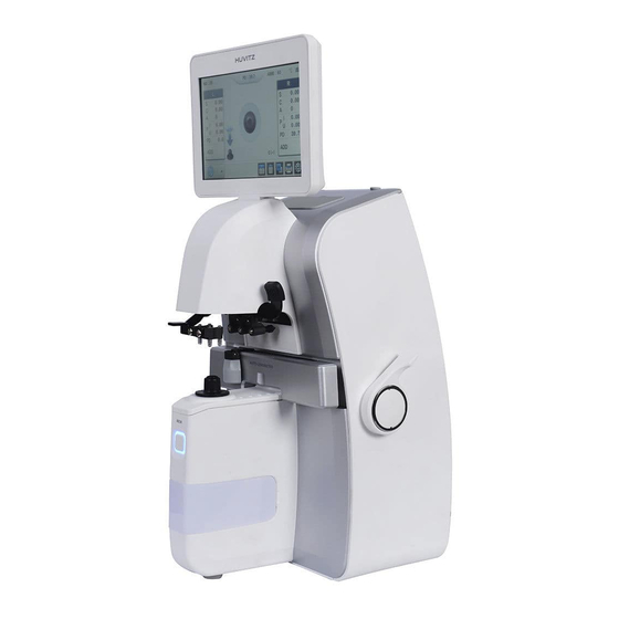
1.1. Equipment Summary Auto Lensmeter HLM-9000 is a machine to generate Sph, Cyl and Axis information of lens by measuring refraction of the lens. Auto Lensmeter HLM-9000 also has functions to measure PD (=pupillary distance) and UV, BLUE transmission. Auto Lensmeter HLM- 9000can measure both unprocessed single lens and eyeglass lens with frames. -
Page 7: Safety Information
-------------------------------------------------------------------HLM-9000 Operator’s Manual Safety Information 2.1. Introduction Safety is primary responsibility for all people. Safe use of this equipment is a concern for installer, user, operator and administrator. Any person shall be familiarized with the contents of this Operator’s Manual before installing, using, cleaning, repairing or adjusting this equipment and its supplementary items. -
Page 8: Safety Symbols
HLM-9000 Operator’s Manual------------------------------------------------------------------ INFORMATION “Information” is to generate information needed on each page that is appropriate at the phase. 2.2. Safety Symbols The International Electrotechnical Commission (IEC) has established a set of signs on medical electronic devices by classifying caution or association of electronic danger. - Page 9 -------------------------------------------------------------------HLM-9000 Operator’s Manual Consult instructions for use. Signifies year of production and producer. Manufacturer Authorized Representative in the European Community It signifies a safe earthing point where safe earth is fixated on sash. For safety, connect protective earth to conductive part of class I apparatus.
- Page 10 HLM-9000 Operator’s Manual------------------------------------------------------------------ Humidity Limitation Atmospheric Pressure Limitation This side up Fragile , handle with care Do not use hand hooks Keep DRY Stacking Limit by Number Keep away from sunlight ОсОО «МЕДОФФ» www.medoff.net...
-
Page 11: Environmental Symbol
-------------------------------------------------------------------HLM-9000 Operator’s Manual Huvitz Symol Other Sign External series connection port. User can transmit saved data to other equipment of Huvitz or other devices such as a PC. 2.3. Environmental Symbol Avoid following environments for operation or storage of this equipment. - Page 12 A place nearby a heating apparatus. Do not disassemble the product. Huvitz will not be held responsible for any negligence regarding such action. Do not connect the AC power adapter before all parts are fully assembled. It can lead to a malfunction.
- Page 13 -------------------------------------------------------------------HLM-9000 Operator’s Manual ℉-104℉) during transportation or storage. Humidity shall be maintained around 50%~80% during normal operation, transportation storage. Avoid environments where the equipment can be exposed to excessive pressure or vibration. Assured temperature and humidity for equipment during operation or non- operation are as the following: Operation: Linear decline at temperatures between +10°C ~ +31°C and 80%...
-
Page 14: Safety Precaution
3. This equipment shall be operated by or under supervision of a well-trained and capable person. 4. Repair of this equipment shall be handled by service personnel at Huvitz or a person with equivalent certification. 5. Customer’s care over this equipment shall be done only according to the Operator’s Manual and Service Instruction. - Page 15 -------------------------------------------------------------------HLM-9000 Operator’s Manual 8. This equipment shall be used with supplementary articles provided by Huvitz. If a customer intends to use supplementary articles of other manufacturers, user safety of those articles shall be inspected and certified by Huvitz or manufacturers of those articles.
- Page 16 HLM-9000 Operator’s Manual------------------------------------------------------------------ Increase the separation between the equipment Connect the equipment into an outlet on a circuit different from that to which the other device(s) are connected Consult the manufacturer or field service technician for help 18. "External equipment intended for connection to signal input, signal output or other connectors, shall comply with relevant IEC standard (e.g., IEC 60950 for IT...
-
Page 17: Feature
-------------------------------------------------------------------HLM-9000 Operator’s Manual Feature Quick and convenient measurement of refraction and center of a lens. When measuring an eyeglass, single/both PD are measure automatically with refraction of each lens. Measurement of UV and Blue transmission of a lens. Wide range of measurement from –25D to +25D. -
Page 18: Instructions For Use
HLM-9000 Operator’s Manual------------------------------------------------------------------ Instructions for Use Do not hit or drop the equipment. Strong pressure might damage the equipment. Strong pressure can affect the function of the equipment. Thus, always handle with care. Install the equipment in a stable place without vibration to maintain normal condition. -
Page 19: Composition
-------------------------------------------------------------------HLM-9000 Operator’s Manual Composition 5.1. Main Parts 렌 렌 즈 즈 받 받 침 침 대 대 [Picture 5-1. Names of parts (I)] 1. Touch LCD Screen 6. UV, BLUE Cover 2. PD Sensor 7. Marking Lever 3. Lens Holder Lever 8. - Page 20 HLM-9000 Operator’s Manual------------------------------------------------------------------ [Picture 5-2. Names of Parts (II)] [Picture 5-3. Names of parts (III)] 1. Power Switch 2. RS-232 Connector 3. Power Connector 3. USB Connector ОсОО «МЕДОФФ» www.medoff.net...
-
Page 21: Supplementary Articles
-------------------------------------------------------------------HLM-9000 Operator’s Manual 5.2. Supplementary Articles Printing Paper: 2 roll of paper for printing Fuse (250V 3.15A): (2) Operator’s Manual: Operation guide for users Power Cable (1.5m) Dust Preventive Cap: a cap to prevent dust from entering (1) Contact lens tweezer: a tool to pick up contact lenses... -
Page 22: Equipment Installation And Preparation
HLM-9000 Operator’s Manual------------------------------------------------------------------ Equipment Installation and Preparation 6.1. Parts Inspection Inspect supplementary articles. ① Open the box and make sure all articles are there (printing paper, dust cover, lens towel, Operator’s Manual and etc.). Remove protection tapes. ② Remove protection tapes on lens holder, lens cap, marking lever and UV, Blue cover. - Page 23 -------------------------------------------------------------------HLM-9000 Operator’s Manual [Picture 6-1. Screen showing an initialize error] [Picture 6-2. Screen showing an initialize error] ОсОО «МЕДОФФ» www.medoff.net...
-
Page 24: Screen Saver
HLM-9000 Operator’s Manual------------------------------------------------------------------ Turn on the equipment, and make sure there are not any objects on the lens cap. If a message that says, “Initialize error” is displayed as shown in [Picture 6-1], check to see there are any objects placed on the lens cap or pinhole, and remove if there is any. -
Page 25: Button Composition
-------------------------------------------------------------------HLM-9000 Operator’s Manual Button Composition 7.1. Button Composition According to Measuring Mode General Lens Measurement Screen Buttons Progressive Lens Measurement Screen Buttons Auto Detect Mode(General/ Progressive Lens) Screen Buttons Contact Lens Measurement Screen Buttons UV, BLUE Lens Measurement Screen Buttons [Picture 7-1. -
Page 26: Use Of Buttons
HLM-9000 Operator’s Manual------------------------------------------------------------------ 7.2. Use of Buttons General Lens Screen to measure general lens (including lens for sunglasses) Progressive Lens Screen to measure progressive multifocal lens Auto Detect Mode Determine the type of lens (general or progressive) currently being measured, and then convert to progressive lens measurement screen automatically if the lens is a progressive lens. - Page 27 -------------------------------------------------------------------HLM-9000 Operator’s Manual S→R Change to left/right lens or left/right of an eyeglass on single eye lens. R/L→S Change from left/right lens of eyeglass to single eye lens mode. CLEAR Initialize data. TRNS Reverse signs on cylinder value. PRINT Print out current data and delete data information.
- Page 28 HLM-9000 Operator’s Manual------------------------------------------------------------------ Change screen to settings. START / STOP Start/stop measuring current data on contact lens measurement screen and save the average. Adjust current transmission to 100% on UV, BLUE measurement screen. MEM (Save) Button Save current measurement. ОсОО «МЕДОФФ» www.medoff.net...
-
Page 29: Screen Composition
-------------------------------------------------------------------HLM-9000 Operator’s Manual Screen Composition 8.1. Measurement Screen 3. Connection Status (USB, WIFI, DR) 1. Serial Number 2. Both Eyes PD 5. ABBE Value 4. Measurement Data 7. Measurement Status 11. Measurement Lens Activation 9. Prism Status 6. Current Measurement 8. -
Page 30: Specifics
HLM-9000 Operator’s Manual------------------------------------------------------------------ 8.1.1. Specifics Serial Number ① Serial number is marked for customer identification. Both Eyes PD ② Both Eyes PD, a sum of left PD and right PD is marked. Connection Status (USB, WIFI, DR) ③ USB, WIFI and DR (phoropter) connection statuses are marked. - Page 31 -------------------------------------------------------------------HLM-9000 Operator’s Manual INFORMATION Curved lens indicates a general lens has been placed on the lens cap. Measurement Position ⑧ The position currently being measure is marked with a cross mark. : Center is aligned within 0.5 prisms. : Center is precisely aligned, and measuring point can be marked after angle adjustment.
-
Page 32: Progressive Lens Screen
HLM-9000 Operator’s Manual------------------------------------------------------------------ 8.2. Progressive Lens Screen 1. Distance Viewing Zone Measurement Position Near Viewing Zone Measurement Position [Picture 8-2. Progressive lens screen composition] 8.2.1. Specifics Distance viewing zone Measurement Position ① Position of current measurement is indicated while searching for the center of... -
Page 33: Auto Detect Mode
-------------------------------------------------------------------HLM-9000 Operator’s Manual distance viewing zone. Near viewing zone Measurement Position ② Position of current measurement is indicated while searching for the center of near viewing zone. 8.3. Auto Detect Mode [Picture 8-3. Auto detect mode screen composition] 8.3.1. Specifics... -
Page 34: Contact Lens Screen
HLM-9000 Operator’s Manual------------------------------------------------------------------ 8.4. Contact Lens Screen 1. Start/Finish Saving 2. Reliability Graph [Picture 8-4. Contact lens screen composition] 8.4.1. Specifics Start/Finish Saving ① Start recording results of consecutive measurement. Start saving button will change its shape to finish saving button after pressing it. (Finish: Average of all measurement results are calculated and saved.) -
Page 35: Uv, Blue Screen
-------------------------------------------------------------------HLM-9000 Operator’s Manual 8.5. UV, BLUE Screen 1. UV, BLUE Transmission 3. UV, BLUE Activation Status 2. UV, BLUE lens 4. Transmission Status 100% measurement position guide [Picture 8-5-1. UV screen composition] [Picture 8-5-2. BLUE screen composition] ОсОО «МЕДОФФ» www.medoff.net... -
Page 36: Specifics
HLM-9000 Operator’s Manual------------------------------------------------------------------ 8.5.1. Specifics UV, BLUE Transmission ① UV, BLUE transmission of lens is indicated in a bar graph and percentage. UV, BLUE lens measurement position guide ② [ UV ] [ Blue ] [Picture 8-5-3. UV, BLUE screen composition] UV, BLUE Activation Status ③... -
Page 37: Setup Screen
-------------------------------------------------------------------HLM-9000 Operator’s Manual 8.6. Setup Screen 8.6.1. Specifics [Picture 8-6-1. Setup screen composition - MEASURE] PD Mode Choose to enable PD function. - Standard: Enable the function. - Averaging: Set to equalize RPD and LPD when the difference between RPD and LPD is less than 3mm. - Page 38 HLM-9000 Operator’s Manual------------------------------------------------------------------ Prism Direction Set direction of cross mark movement on measurement screen. - Comfortable: Set cross mark to move in the direction of lens movement for user convenience. (Prism Display: Prism angle and cross mark position on screen might not accord during PB setting.)
- Page 39 -------------------------------------------------------------------HLM-9000 Operator’s Manual - Manual: User will start measurement by pressing [START] button, and stop by pressing [STOP] button. - Automatic: Start/stop contact lens measurement during the duration user has set (unit: second). (Duration setting for consecutive measurement can be done on USER SETUP screen.)
- Page 40 HLM-9000 Operator’s Manual------------------------------------------------------------------ - 0.01: Set prism value indication unit to 0.01. Cylinder Mode Set how to indicate cylinder sign. - Mix: Mark cylinder sign as (+) when average power is (+). Mark cylinder sign as ( ) when average power is ( - +: Mark cylinder sign as (+) at all times.
- Page 41 -------------------------------------------------------------------HLM-9000 Operator’s Manual Measure Display Set how to display data. - SCA: Set data to be displayed as S, C, A. - S.E: Set data to be displayed as S.E. Language Select language to display user setting menu. - English: Display menu in English.
- Page 42 HLM-9000 Operator’s Manual------------------------------------------------------------------ Printer Mode Choose to use a function to print automatically after measurement. - Automatic: Results will be printed automatically after measuring right and left lenses and the lens is removed from the lens cap. - Manual: Disable the function.
- Page 43 -------------------------------------------------------------------HLM-9000 Operator’s Manual [Picture 8-6-3-1. Name and phone number entry screen] : Convert between upper case/lower case : Delete all texts. : (Back Space) delete one letter in front of the cursor. : Change position of cursor from first line to and from second line.
- Page 44 HLM-9000 Operator’s Manual------------------------------------------------------------------ [Picture 8-6-3-2. Date and time setting screen] [Picture 8-6-4. Set up screen composition - COMMUNICATION] ОсОО «МЕДОФФ» www.medoff.net...
- Page 45 -------------------------------------------------------------------HLM-9000 Operator’s Manual RS 232C Set RS-232C (external) communication protocol. - OFF: Disable the function. - Wave Line: Enable single direction communication protocol function between HLM and HRK, HDR. - LMTORK: Enable bi-direction communication protocol function between HLM and HRK, HDR.
- Page 46 HLM-9000 Operator’s Manual------------------------------------------------------------------ using Wifi. - On: Enable the function. - Off: Disable the function. Trans. Type Select data transfer type for wireless communication data transfer using Wifi. - Auto: Transfer data to all currently connected devices without consulting with user, and display the result.
- Page 47 -------------------------------------------------------------------HLM-9000 Operator’s Manual IP ROOM NAME/IP Address 1 ~ 5 : Select opponent device(s) to transfer wireless communication data using Wifi (maximum four can be selected among 1~10 previously registered IP addresses.) - ROOM: Touch on the name of opponent device to change its name for easier distinction.
- Page 48 HLM-9000 Operator’s Manual------------------------------------------------------------------ - Mid: Enable sound and set volume to medium. - High: Enable sound and set volume to high. Sleep Mode Enable/disable screen saver function. - On: Enable the function. - Off: Disable the function. Color Setting Adjust color temperature of LCD display.
-
Page 49: Measurement Data Transmission Using Wifi
8.7. Measurement Data Transmission using WiFi Measurement data can be transmitted to Huvitz Co. Ltd, phoropter using a WiFi network. Data can be transmitted without direct data cable connection using this function. Thus, it does not require any additional installations or take up installation spaces as it uses wireless network. - Page 50 HLM-9000 Operator’s Manual------------------------------------------------------------------ IP Assignment Mode: DHCP Encryption Method: WPA2-PSK AP SSID: A name to distinguish AP. Set as you like. AP PASSWORD: Password. Set as you like. After setting, please remember the AP SSID and AP PASSWORD to connect to WiFi network.
- Page 51 -------------------------------------------------------------------HLM-9000 Operator’s Manual 1. Convert to User SETUP Mode, and select WIFI on page 2. 2. Turn on WiFi to use transmission function. 3. Set TRANSFER TYPE to set up data transmission method. 4. Press on the AP SSID entry window to enter SSID. When SSID is not known, press SCAN button on the right to select from available AP SSID.
- Page 52 HLM-9000 Operator’s Manual------------------------------------------------------------------ [Figure 8-7-3. WiFi AP Password Verification Result Screen] Phoropter Connection Setting for lensmeter ④ [Figure 8-7-4. WIFi Phoropter Connection Setting Screen] 1. Convert to User SETUP Mode, and select page 2 on network tab. ОсОО «МЕДОФФ» www.medoff.net...
-
Page 53: Check Wifi Network Status
-------------------------------------------------------------------HLM-9000 Operator’s Manual 2. Enter r information for phoropter to connect on each field. : Select if phoropter will use the data transmission function. : Enter a name for the phoropter. Enter the IP address of the phoropter. (Refer to ②.) If there are more than five phoropters to enter, additional phoropters can be entered under page 3. - Page 54 HLM-9000 Operator’s Manual------------------------------------------------------------------ : Phoropter connection process is in progress. For user convenience, the machine will operate to make attempts to connect to AP automatically while the power is on if it is not connected to AP. Thus, user does not have to go through the AP connection process.
- Page 55 -------------------------------------------------------------------HLM-9000 Operator’s Manual [Figure 8-7-6. Phoropter Connection Status Screen] Status of each phoropter will be shown graphically on the four windows. Under the windows are the names of phoropters set by user. Graphic indications are described below. : Connected to phoropter normally.
-
Page 56: Measurement Data Transmission
HLM-9000 Operator’s Manual------------------------------------------------------------------ : There is not a phoropter selected. If there is a connection error and the current status is on (2), try connecting again by pressing on the phoropter window. Connection takes up to 10 seconds depending on the environment, and the icon will change to (1) if the connection attempt was successful. - Page 57 -------------------------------------------------------------------HLM-9000 Operator’s Manual [Figure 8-7-7. Transmission Complete on AUTO Mode] After confirming the result, press OK to turn off the status screen. If there are connection errors on one or more phoropters, the setting will be converted to MANUAL without transmitting the data.
- Page 58 HLM-9000 Operator’s Manual------------------------------------------------------------------ [Figure 8-7-8. Current Phoropter Connection Status Screen on MANUAL Mode] Transmit data to a phoropter of user’s choice by pressing on the phoropter window. If the phoropter is not connected, try to reconnect by pressing the window as shown in 8.7.2.
-
Page 59: Print Format
-------------------------------------------------------------------HLM-9000 Operator’s Manual 8.8. Print Format Print format is as the below. [Picture 8-8. Print format for eyeglass lens] ОсОО «МЕДОФФ» www.medoff.net... -
Page 60: Measurement
HLM-9000 Operator’s Manual------------------------------------------------------------------ Measurement 9.1. General Lens [Picture 9-1. How to measure a general lens] Reset measurement status by pressing ‘CLEAR’ button ( ). Set ① measurement lens on the top right corner of the screen to ‘S’. (However, ‘R’ will be displayed if ‘Side Allocation’... - Page 61 -------------------------------------------------------------------HLM-9000 Operator’s Manual OFF center ALIGNMENT OK MARKING OK [Picture 9-2. Focus adjustment] For a lens with astigmatism power, rotate the lens so the astigmatism angle is ④ 180°. INFORMATION There is no need to adjust astigmatism angle to 180° when the lens is without astigmatism power or when there is no need to mark astigmatism focus and cylinder axis.
- Page 62 HLM-9000 Operator’s Manual------------------------------------------------------------------ INFORMATION ‘Storage Mode’ function is to save measurement automatically 1 second after ‘MARKING OK’ display when the function is enabled in User Set Up screen. Press ‘PRINT’ button to print out the measurement. ⑥ INFORMATION The drawings below will be displayed on the bottom left corner of the screen according to presence of a lens.
-
Page 63: Eyeglass Lens
-------------------------------------------------------------------HLM-9000 Operator’s Manual INFORMATION A drawing of the lens cap with a lens will be displayed on the bottom left corner of the screen when a lens with power is placed. CAUTION After placing a lens on the lens cap, do not apply sudden pressure towards the downside, or make a rapid movement to avoid damaging/breaking the lens. - Page 64 HLM-9000 Operator’s Manual------------------------------------------------------------------ Press ‘S->R’ button ( ) to enter eyeglass lens measurement ① environment. ‘L’ and ‘R’ will be displayed on the top of the screen. CAUTION Activated data result screen indicates the lens currently being measured, and inactivated screen indicates the opposite side lens.
- Page 65 -------------------------------------------------------------------HLM-9000 Operator’s Manual CAUTION When PD function is unavailable or disabled, or when side allocation function is manual, press ‘S->R’ button ( ) to select a lens to measure. Adjust focus until ‘MARKING OK’ is displayed. After PD function is on, place ⑥...
-
Page 66: Progressive Multifocal Lens
HLM-9000 Operator’s Manual------------------------------------------------------------------ NOTE For cylinder-only lenses, or sharply warped frames, the PD measurement accuracy may be lowered. 9.3. Progressive Multifocal Lens 9.3.1. Structure of Progressive Multifocal Lens A lens before processing Lens Table Near Center Far Center [Picture 9-5. Structure of single progressive lens] INFORMATION Horizontal line of a lens shall be placed parallel to the lens table. - Page 67 -------------------------------------------------------------------HLM-9000 Operator’s Manual INFORMATION As shown on the picture above, distance viewing zone of the lens shall be placed near the lens table. Framed Lens 2~3mm 2~3mm [Picture 9-6. Structure of framed progressive lens] INFORMATION Sizes of progressive multifocal lenses vary according to manufacturers.
-
Page 68: Judgment Of Progressive Multifocal Lens
HLM-9000 Operator’s Manual------------------------------------------------------------------ INFORMATION Do not pick up the lens during measurement. Fixating angle of lens holder must be maintained. During measurement, lens shall be moved left-right or forward-backward. Picking up the lens might result in incorrect measurement. 9.3.2. Judgment of Progressive Multifocal Lens Make sure the icon on the bottom left of the screen is the same as the picture ①... -
Page 69: Distance Viewing Zone Measurement
-------------------------------------------------------------------HLM-9000 Operator’s Manual Then, the screen will automatically convert to progressive lens measurement screen. [Picture 9-8. Change of status icon] INFORMATION When progressive power is smaller than 1D, automated judgment might not work. such cases, press current Measurement Mode button ) to change to progressive lens measurement mode manually. -
Page 70: Near Viewing Zone Measurement
HLM-9000 Operator’s Manual------------------------------------------------------------------ Distance viewing zone power will be auto-saved when the cross mark reaches ③ the distance viewing zone target center, and it will move on to near viewing zone measurement. INFORMATION It is difficult to auto-determine the distance viewing zone center for a lens with progressive band expanded to distance viewing zone. - Page 71 -------------------------------------------------------------------HLM-9000 Operator’s Manual INFORMATION If the horizontal indicator is incorrect, move slightly to right for a right lens or to left for a left lens since near viewing zone center is moved 2~3 mm toward the frame center as mention in the framed lens structure.
-
Page 72: Troubleshoot During Progressive Lens Measurement (Auto Detect Mode)
HLM-9000 Operator’s Manual------------------------------------------------------------------ INFORMATION Some of the old type progressive lenses do not comply with 2~3mm standard toward the frame center. 9.3.5. Troubleshoot during Progressive Lens Measurement (Auto Detect Mode) ① When a progressive lens has failed to be auto-determined. -
Page 73: General Multifocal Lens
-------------------------------------------------------------------HLM-9000 Operator’s Manual When it is difficult to find near viewing zone. ④ Cause 1: If near viewing zone is located near the bottom frame, it is difficult to find. Countermeasure: Pull up the lens holder, and find the near viewing zone center while pulling the frame. -
Page 74: Measurement On Progressive Screen
HLM-9000 Operator’s Manual------------------------------------------------------------------ If you wish to set second ADD value, press ‘ADD’ button ( ④ Place the lens on the third focal center, and press ‘MEM’ button. Second ‘ADD’ ⑤ value will be saved. 9.4.2. Measurement on Progressive Screen To convert to progressive lens measurement screen, press Current ①... - Page 75 -------------------------------------------------------------------HLM-9000 Operator’s Manual Remove moist using a clean lens towel. Soft contact lens can tear up easily, ② and remove moist with light touches before waiting 5 seconds for lens to recover its curved shape. Pick up the soft contact lens using a tong provided as a supplementary article, ③...
-
Page 76: Uv, Blue Transmission
HLM-9000 Operator’s Manual------------------------------------------------------------------ 9.6. UV, BLUE Transmission [Picture 9-10. How to measure UV, BLUE transmission] Press Measurement Mode button ( ), and select ‘UV, BLUE’ ① lens measurement mode ( Pull out the UV, BLUE cover. ② Press UV button on the screen, and select to activate the UV measurement ③... - Page 77 -------------------------------------------------------------------HLM-9000 Operator’s Manual When UV or BLUE transmission is not 100% without a lens, press ‘CAL’ ④ button ( ) to readjust UV or BLUE transmission to 100%. Place a lens on the UV, BLUE optic unit. ⑤ Press ‘MEM’ button to save UV or BLUE transmission, and press ‘PRINT’...
-
Page 78: Measuring Point Marking
HLM-9000 Operator’s Manual------------------------------------------------------------------ 9.7. Measuring Point Marking 9.7.1. Without Astigmatism Place a lens on the lens cap, and move the lens until ‘MARKING OK’ is ① displayed. Tilt the marking lever to reach 90° to horizontal. ② Pull down the marking lever to mark. -
Page 79: With Astigmatism
-------------------------------------------------------------------HLM-9000 Operator’s Manual 9.7.2. With Astigmatism Place a lens on the lens cap, and move until ‘MARKING OK’ is displayed. ① Adjust lens to the angle on the prescription while maintaining ‘MARKING OK’. ② Tilt the marking lever to 90 to horizontal and mark. -
Page 80: Self-Diagnosis And Maintenance/Repair
HLM-9000 Operator’s Manual------------------------------------------------------------------ 10. Self-diagnosis and maintenance/repair 10.1. Prior to calling a serviceman Warning appears on the screen when there is a problem or when this device malfunctions. Take the following measures in case of the following. Contact a sales distributor after turning off the power when the device does not resume normal operation even after taking the following measures. -
Page 81: Printing Paper Replacement
-------------------------------------------------------------------HLM-9000 Operator’s Manual Message Root causes Measures Wait until the data transfer Data Transmitting… State for transmitting data. is complete. 10.2. Printing Paper Replacement [Picture 10-1. How to replace printing paper] Press the button on the side to open the cover. -
Page 82: Fuse Replacement
Fuse Box [Picture 10-2. Fuse replacement] Pull the fuse box to remove. ① Replace with a new fuse. ② Place the new fuse box in the fuse location. ③ INFORMATION Auto Lensmeter HLM-9000 uses a 250V, T3.15AL fuse. ОсОО «МЕДОФФ» www.medoff.net... -
Page 83: Storage
-------------------------------------------------------------------HLM-9000 Operator’s Manual 10.4. Storage While not use, cover up the device with the dust cover as shown in Picture 10-3 for storage. [Picture 10-3. How to store while not use] If you do not plan to use the device for more than a week, place the dust cap on lens cap as shown in Picture 10-4. -
Page 84: Disposal
HLM-9000 Operator’s Manual------------------------------------------------------------------ [Picture 10-4. For long-term storage] 10.5. Disposal NOTE Please obey the law relating to the equipment and its part to discard the equipment or its part(s). For example, discarding a lithium battery is a threat to the environment. - Page 85 -------------------------------------------------------------------HLM-9000 Operator’s Manual [Picture 10-5. Measuring Error screen] Measuring Error: Is displayed when there is no signal. Is displayed when there is out of range signal. Contact lens measurement, when signal is bad, appear. ОсОО «МЕДОФФ» www.medoff.net...
-
Page 86: How To Clean Pinhole
HLM-9000 Operator’s Manual------------------------------------------------------------------ [Picture 10-6. Data Transmitting screen] Data Transmitting…: Shows a state in which the data transmission. (If you set the setup mode COMMUNICATION->RS 232C->LMTORK) 10.7. How to Clean Pinhole If the S, C and A values are not 0 when the equipment starts up, clean the pinhole. - Page 87 Do not use liquid such as alcohol or acetone as it can dissolve the adhesive on the pinhole. If the S, C and A values are not 0 after cleaning the pinhole, please inquire with an authorized dealer or Huvitz Service Department. ОсОО «МЕДОФФ» www.medoff.net...
-
Page 88: Major Specification
HLM-9000 Operator’s Manual------------------------------------------------------------------ 11. Major Specification Measurement Range Spherical Power 0D ~ ±25D (0.25/0.125/0.06/0.01) Cylinder Power 0D ~ ±10.00D (0.25/0.125/0.06/0.01) Cylinder Axis ~ 180 step) Progressive Power 0 ~ 10D (0.25/0.125/0.06/0.01) Prism 0 ~ 20 (0.25/0.125/0.06/0.01) Wireless I/F Protocol IEEE802.11b WiFi... - Page 89 -------------------------------------------------------------------HLM-9000 Operator’s Manual Tiltable 7”Color LCD IPS Panel (800*480) Screen Touch panel Printer Auto cutter Printer RS-232, Wifi (802.11b, 2.4GHz) Interface USB A Port (service) Communication Speed 9600,19200,38400,57600,115200 bps (BPS) Product Size 222(W) x 240(D) x 370(H) mm Product Weight 5.4Kg...
-
Page 90: Emc Information
Manufacturer announcement – electromagnetic waves trouble Electromagnetic waves trouble HLM-9000 should be used in the below mentioned electromagnetic wave environment. HLM-9000 purchaser or user needs to confirm whether HLM-9000 is used in this type of environment. Trouble test Question of... - Page 91 Manufacturer announcement – electromagnetic waves tolerance electromagnetic waves tolerance HLM-9000 is to be used in the below designated electromagnetic wave environment. HLM-9000 customer and user need to guarantee that the HLM-9000 will be used in this type of environment. Tolerance test...
- Page 92 3 Vrms Portable and mobile RF electromagnetic communications equipment kHz∼80 field should be used no closer to any part of the HLM-9000, IEC 61000- including cables, than the 4-6 recommended separation distance calculated from the equation applicable to the frequency of the transmitter.
- Page 93 RF transmitters, an electromagnetic site survey should be considered. If the measured field strength in the location in which the HLM-9000 is used exceeds the applicable RF compliance level above, the HLM-9000 should be observed to verify normal operation.
- Page 94 RF transmitter, field inspection is required. If the electric intensity used by the HLM-9000 that is measured at the outside of the shielded location exceeds 3 V/m, then it is necessary to observe and verify whether HLM-9000 operates normally. If abnormal operation is observed, then re-place HLM-9000 or use other shielded location that has increasingly higher RF shield effect and filter decrease.
-
Page 95: Service Information
Dateof Purchase: Name of Seller: Seller Address: Seller Phone: Model Number: Serial Number: If you have trouble contacting the place of purchase, contact the service department at Huvitz directly using the addresses and phone numbers below. ОсОО «МЕДОФФ» www.medoff.net... - Page 96 HLM-9000 Operator’s Manual------------------------------------------------------------------ Huvitz Co., Ltd. (HQ) Tel: 031-428-9100 (Primary) 298-29 Gongdan-ro, Gunpo-si, Gyeonggi- Fax: 031-477-9022(C/S) do 435-862 http://www.huvitz.com e-mail: svc@huvitz.com (Manufacturer) 91-beongil 16-17(Hogye-dong), LS-ro, Tel: 031-428-9100 Dongan-gu, Anyang-si, Gyeonggi-do 431- Fax: 031-477-8618 EU Representative Schiffgraben 41, 30175 Hannover, Germany...
Need help?
Do you have a question about the HLM-9000 and is the answer not in the manual?
Questions and answers