Paradox DIGIPLEX DGP-848 Reference And Installation Manual
Hide thumbs
Also See for DIGIPLEX DGP-848:
- System manager's manual (28 pages) ,
- Programming manual (48 pages)

Related Manuals for Paradox DIGIPLEX DGP-848


Summary of Contents for Paradox DIGIPLEX DGP-848
- Page 1 Digiplex Control Panel (DGP-848) - V4.1 DGP-848 Reference and Installation Manual Includes DGP2-641BL/RB Installation Instructions...
-
Page 3: Table Of Contents
Closing Delinquency .............. 29 Decimal Programming.............. 9 Hexadecimal Programming............9 Level Programming ..............10 Dialer Options ..............29 Paradox Memory Key............. 10 Telephone Line Monitoring ............ 29 Tone/pulse Dialing ..............29 Zone Programming............11 Pulse Ratio ................29 Busy Tone Detection ............. 30 Zone Numbering .............. - Page 4 Power Save Mode ..............37 PC Password................. 44 Auto Trouble Shutdown ............37 PC Telephone Number............44 No AC Fail Display..............37 Call WinLoad ................. 44 Answer WinLoad ..............44 Event Buffer Transmission ............ 44 Access Codes ..............38 Call Back Feature..............45 Installer Code.................
-
Page 5: Introduction
• Remote and local programming of all modules CTR-21 APPROVAL • Upload/download capability using new WinLoad Security The Digiplex DGP-848 control panel meets the European Union ® System Management software for Windows Common Technical Requirement CTR-21. The CTR-21 • Addressable PIRs and door contacts requirement is an electrical standard that defines the analogue •... -
Page 6: Installation
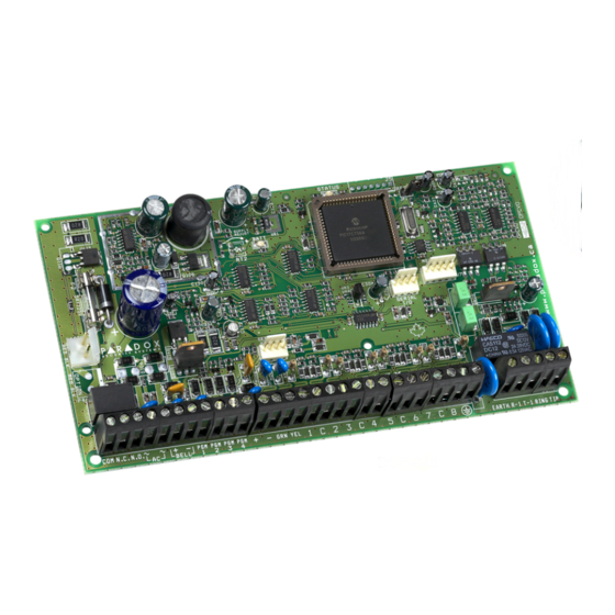
Installation 2.1 Location & Mounting Auxiliary power will resume once the overload condition has restored. For details on available output power, please refer to Before mounting the cabinet, push the five white nylon mounting Figure 3 on page 3. For more information on how to calculate studs into the back of the cabinet. - Page 7 Figure 3: Digiplex Control Panel PCB Layout Four pin connector can be Charging and battery test LED “STATUS” LED: Short flash = Panel OK used for quick installation of a (every 64 seconds) Long flash = TLM Fault Digiplex keypad or module. Constant = Dialer on-line = Panel error/off-line...
-
Page 8: Calculating Power Requirements
2.8 Calculating Power Requirements Table 1: Milliamp Consumption Table mA used by Description QTY. Total mA each Grafica Graphic LCD Keypads (DNE-K07): _______ 130mA = __________ mA LCD Keypads (DGP2-641BL): _______ 110mA = __________ mA LCD Keypads with Built-in Reader (DGP2-641RB): _______ 120mA = __________ mA... - Page 9 Figure 4: Sample Power Requirement Calculations CONTROL PANEL 16.5VAC 40VA = 700mA OUTPUT Transformer Power required by devices connected to control panel’s auxiliary output must not exceed the auxiliary output’s limit: (A) + (B) + (C) + (D) + (E) + (F) + (G) + = 455mA<700mA = OK 15m (50ft.) 61m(200ft.) LCD Keypad (DGP2-641BL)
-
Page 10: Programmable Outputs
2.9 Programmable Outputs houses the control panel, connect the exposed shield to a cold water pipe or any other earth ground available, while leaving the The Digiplex control panel comes standard with PGM1 and PGM2. shield at the other end of the cable open (floating). The same PGM3 to PGM5 are optional. -
Page 11: Double Zone Connections
2.12 Double Zone Connections 2.13 Keypad Zone Connections Enabling the ATZ feature (see section 4.8 on page 16) allows you Each LED and LCD keypad has one hardwired input terminal to install two detection devices per input terminal. The ATZ feature allowing you to connect a detector or door contact directly to the is a software oriented feature. - Page 12 smoke detector sends a CleanMe signal, the control panel will generate a Zone Fault trouble and if programmed will transmit the Fire Loop report code to the monitoring station. The trouble will be cleared if there is no CleanMe signal for 255 seconds. If an alarm occurs, the trouble will be cleared until it is detected again.
-
Page 13: Programming Methods
You can also copy the programmed contents of one Digiplex program. control panel into as many Digiplex control panels as you need by using the Paradox Memory Key (see section 3.7 on page 10). Each Enter the 3-digit [ ] and required [... -
Page 14: Level Programming
Copy the programmed contents of one Digiplex control panel into before removing the Memory Key. the Paradox Memory Key. Then copy the contents of the Paradox Memory Key into as many Digiplex control panels as you need. This saves you a lot of time. All you have to do is program one Digiplex control panel, then download the programmed contents to other control panels in less than 5 seconds. -
Page 15: Zone Programming
Zone Programming All detection devices connected to the control panel, keypads and zone expansion modules must be assigned to a zone and that zone must be defined as described in this section: Zone Numbering [001] to [048]: • Serial number of the device/module •... -
Page 16: Zone Numbering
4.1 Zone Numbering 4.2.2 Entry Delays 1 to 4 [101] [148]: F ECTIONS IRST DIGIT [001] [048] ECTIONS When an armed zone defined as an Entry Delay opens, the control The Zone Numbering feature allows you to assign any detection panel will not generate an alarm until the programmed Entry Delay device in the system to any of the 48 zones. -
Page 17: Zone Partition Assignment
Figure 15: Delayed 24-hr. Fire Zone Figure 16: Bell/Siren Output During Fire Alarm Delayed Fire Zone Triggered Activate bell/siren output & delay report transmission for 30 seconds. 4.2.9 Stay Delay Zone [101] [148]: F ECTIONS IRST DIGIT Has the zone closed within When a Stay Delay zone is armed using the Regular or Force 30 seconds? -
Page 18: Zone Labels
[5] & [6] complete Grafica user manual is available on our website at ECTIONS PTIONS Zone Alarm Type www.paradox.ca. Steady Audible Alarm Pulsed Audible Alarm Zone Labels: Sections [451] to [498] represent Zones 01 to 48. Silent Alarm Generates a report only Table 3: Keys •... - Page 19 Table 5: Hebrew Keypad Letter Assignment Table 8: Hebrew Special Characters Catalogue Table 6: Russian Keypad Letter Assignment Table 7: Special Characters Catalogue Table 9: Russian Special Characters Catalogue DGP-848 Control Panel...
-
Page 20: Input Speed
4.6 Input Speed Figure 17: ATZ Input Terminal Recognition [201] [216] ECTIONS (000 to 255 X 20msec,default: 600ms) The Input Speed defines how quickly the control panel will respond to an open zone detected on any hardwired input terminal. The control panel will not display and/or respond to an open zone until the programmed Input Speed elapses to prevent glitches from causing an alarm or unnecessary reporting.
Need help?
Do you have a question about the DIGIPLEX DGP-848 and is the answer not in the manual?
Questions and answers