Paradox Magellan MG5000 Programming Manual
32-zone wireless transceiver control panel
Hide thumbs
Also See for Magellan MG5000:
- Programming manual (72 pages) ,
- User manual (32 pages) ,
- Reference & installation manual (69 pages)

Related Manuals for Paradox Magellan MG5000


Summary of Contents for Paradox Magellan MG5000
-
Page 1: Programming Guide
32-Zone Wireless Transceiver Control Panel MG5000 V1.4 Programming Guide We hope this product performs to your complete satisfaction. Should you have any questions or comments, please visit www.paradox.com and send us your comments. -
Page 2: Installer Quick Menus
Installer Quick Menus Zones Step Action Details The [ ] key will flash. LED/key on = programmed zone. ] + [ INSTALLER CODE ] may also be used. MAINTENANCE CODE MG32LRF/MG32LED = 2 digits: 01 to 32 ZONE NUMBER MG10LEDV/H = 1 digit: 1 to 0(10) Open/close cover or press learn/tamper switch or press [ ] for hardwired panel/key-... -
Page 3: Walk Test Mode
Walk Test Mode Step Action Details The [ ] key will flash. [ ] may also be used. ] + [ INSTALLER CODE MAINTENANCE CODE Activates or deactivates Walk Test Mode. Installer and Maintenance Codes Step Action Details The [ ] key will flash. [ ] may also be used. -
Page 4: Communicator
Communicator Step Action Details The [ ] key will flash. [ ] may also be used. ] + [ INSTALLER CODE MAINTENANCE CODE [2] = Backup Phone # [3] = Personal Phone #1 [4] = Personal Phone #2 [5] = Personal Phone #3 [6] = Personal Phone #4 [7] = Personal Phone #5 [8] = Pager #... -
Page 5: Table Of Contents
Table of Contents Partition Timers ..............28 Communication Programming......29 Installer Quick Menus..........2 Communication Settings ........... 30 Zones .................. 2 Communication Timers ............. 31 Keypad Zone Number Assignment (Keypad Programming) 2 Special Arming Report Codes (Default = FF)....31 Delays ................. -
Page 6: Things You Should Know
About This Programming Guide This programming guide should be used in conjunction with the MG5000 Reference & Installation Manual which can be downloaded from our website at paradox.com. Use this guide to record the settings programmed for this console. Conventions This symbol designates a warning or important information. -
Page 7: Zone Programming
Zone Programming Refer to the Installer Quick Menu on the inside cover For UL installation, fire zone cannot be Zone Options for zone programming/keypad zone programming. bypassable. Turn off zone option [2]. [1] = Auto-zone Shutdown [2] = Bypassable Zone [3] = RF Supervision Zone Definitions 00 = Zone disabled... -
Page 8: Zone Definition Status
Zone Definition Status Stay/ Sleep Alarm Delay - Stay/ Sleep Alarm Delay - Section [720] is 0 Section [720] is not 0 Zone Description Stay Arm Sleep Arm Fully Arm Stay Arm Sleep Arm Fully Arm Definition Entry Delay 1 As is As is As is... -
Page 9: Wireless Transmitter Serial Number
Wireless Transmitter Serial Number Section Wireless Transmitter Serial Number Section Wireless Transmitter Serial Number [061] Zone 1: ____/____/____/____/____/____ [077] Zone 17: ____/____/____/____/____/____ [062] Zone 2: ____/____/____/____/____/____ [078] Zone 18: ____/____/____/____/____/____ [063] Zone 3: ____/____/____/____/____/____ [079] Zone 19: ____/____/____/____/____/____ [064] Zone 4: ____/____/____/____/____/____ [080] Zone 20: ____/____/____/____/____/____... -
Page 10: Zone Reporting Codes (Default = Ff)
Zone Reporting Codes (Default = FF) Section Alarm Alarm Restore Tamper Tamper Restore [141] Zone 1: _____/_____ _____/_____ _____/_____ _____/_____ [142] Zone 2: _____/_____ _____/_____ _____/_____ _____/_____ [143] Zone 3: _____/_____ _____/_____ _____/_____ _____/_____ [144] Zone 4: _____/_____ _____/_____ _____/_____ _____/_____ [145] Zone 5:... -
Page 11: Programmable Output Programming
Programmable Output Programming Programmable Output Activation/Deactivation Events Section Event Group # Sub-Group # Partition # Default [220] PGM 1: Activation Event (____/____) (____/____) (____/____) 08/99/99* [221] Deactivation Event (____/____) (____/____) (____/____) 00/00/00 [222] PGM 2: Activation Event (____/____) (____/____) (____/____) 09/99/99†... -
Page 12: Event Description
Event Description Event Group # Sub-group # 00 = Zone OK 01 to 32 = Zone number 99 = Any zone number 01 = Zone open 02 = Partition status 00 to 01= N/A 02 = Silent alarm 03 = Buzzer alarm 04 = Steady alarm 05 = Pulsed alarm 06 = Strobe... - Page 13 Event Group # Sub-group # 13 = Cold start wireless module (Partition 1 only) 01 to 16 = Output number 17 to 18 = Wireless repeater 19 to 22 = Wireless keypad 99 = Any output number 14 = Bypass programming 01 to 32 = User number 99 = Any user number 15 = User code activated output (Partition 1 only)
- Page 14 Event Group # Sub-group # 44 = New trouble 00 = N/A (Partition 1 only except sub-group 07 = both partitions) 01 = AC failure 02 = Battery failure 03 = Auxiliary current overload 04 = Bell current overload 05 = Bell disconnected 06 = Clock loss 07 = Fire loop trouble 08 = Fail to communicate to monitoring station telephone #1...
-
Page 15: Programmable Output Options
Programmable Output Options Default: PGM 1 PGM 2 PGM 3 PGM 4 Bold Section: [261] [262] [263] [264] Option PGM Base Time (Off=Sec; On=Min) PGM State (Off=N.O., On=N.C.) PGM Supervision PGM Activation Mode (Off=Steady, On=Pulse) PGM Pulse once every 30 seconds if armed PGM Pulse on any alarm PGM Pulse on any alarm - OFF= Partition 1 On= Partition 2... -
Page 16: Programmable Output Delays
Default: PGM 13 PGM 14 PGM 15 PGM 16 Bold Section: [273] [274] [275] [276] Option PGM Base Time (Off=Sec; On=Min) PGM State (Off=N.O., On=N.C.) PGM Supervision PGM Activation Mode (Off=Steady, On=Pulse) PGM Pulse once every 30 seconds if armed PGM Pulse on any alarm PGM Pulse on any alarm - OFF= Partition 1 On= Partition 2... -
Page 17: Wireless Pgm Signal Strength
Wireless PGM Signal Strength Section Section [321] PGM 1 Wireless PGM Signal Strength [329] PGM 9 Wireless PGM Signal Strength [322] PGM 2 Wireless PGM Signal Strength [330] PGM 10 Wireless PGM Signal Strength [323] PGM 3 Wireless PGM Signal Strength [331] PGM 11 Wireless PGM Signal Strength [324]... -
Page 18: Wireless Repeater Programming (Mg-Rpt1)
Wireless Repeater Programming (MG-RPT1) Wireless Repeater Assignment Section Wireless Repeater Serial Number [545]= Repeater 1 ____/____/____/____/____/____/ [546]= Repeater 2 ____/____/____/____/____/____/ For automatic assignment, press the wireless repeater’s anti-tamper switch while in the respective section. Wireless Repeater Signal Strength Section [548] Wireless Repeater 1 Signal Strength [549] Wireless Repeater 2 Signal Strength... - Page 19 Default: MG-RPT1 #1 MG-RPT1 #2 Bold Section: [553] [563] Option Repeat Wireless Zone 9 Signals Repeat Wireless Zone 10 Signals Repeat Wireless Zone 11 Signals Repeat Wireless Zone 12 Signals Repeat Wireless Zone 13 Signals Repeat Wireless Zone 14 Signals Repeat Wireless Zone 15 Signals Repeat Wireless Zone 16 Signals Default:...
- Page 20 Default: MG-RPT1 #1 MG-RPT1 #2 Bold Section: [556] [566] Option Repeat Wireless 2-Way PGM 1 Signals Repeat Wireless 2-Way PGM 2 Signals Repeat Wireless 2-Way PGM 3 Signals Repeat Wireless 2-Way PGM 4 Signals Repeat Wireless 2-Way PGM 5 Signals Repeat Wireless 2-Way PGM 6 Signals Repeat Wireless 2-Way PGM 7 Signals Repeat Wireless 2-Way PGM 8 Signals...
-
Page 21: Wireless Keypad Programming (Mg32Lrf)
Wireless Keypad Programming (MG32LRF) Automatic Wireless Keypad Assignment After panel power-up, the control panel will open a 10 minute window for Automatic Assignment. Press and hold the [ ] and [ key for three seconds on the respective keypad. The keypad is assigned to the control panel. Up to 4 wireless keypads can be assigned within the ten minute window. -
Page 22: User Programming
User Programming Refer to the Installer Quick Menu on the inside cover for installer or maintenance code programming. Refer to the Master Quick Menu in the MG5000 User Guide for user code/remote control programming. System Codes Section Data Description [395] ____/____/____(147 to lock, other to unlock) Installer Code Lock (default 000) [397]... -
Page 23: User Reporting Codes (Default = Ff)
User Reporting Codes ( Default = FF) Disarming/Cancel Disarming/Cancel Section Arming Section Arming Alarm Alarm [471] = S. Master: ____/____ ____/____ [487] = User 17: ____/____ ____/____ [472] = Master 1: ____/____ ____/____ [488] = User 18: ____/____ ____/____ [473] = Master 2: ____/____ ____/____ [489] = User 19:... -
Page 24: Remote Button Assignment
Remote Button Assignment Programming the MG-REM1/MG-REM2 Warning: When section [610] is accessed, the MG5000 will copy the saved value of that section to all remotes. Section Data (Default: 1BC_) Section Data (Default: 1BC_) [610] Default ______ ______ ______ ______ [627] ______ ______ ______... -
Page 25: System Programming
System Programming [700] General System Options Bold = Default setting Option Partitioning Disabled Enabled Battery charging (350mA or 700mA) 350mA 700mA Audible trouble warning (except AC failure) Disabled Enabled Audible trouble warning on AC failure Disabled Enabled RF jamming supervision Disabled Enabled Exit delay termination... - Page 26 [704] Arming/Disarming Options 2 Bold = Default setting Option Regular arming switches to force arming Disabled Enabled Stay arming switches to stay force arming Disabled Enabled Sleep arming switches to sleep force arming Disabled Enabled Bell squawk when arm/disarm with remote Disabled Enabled Bell squawk when arm/disarm with a keypad...
-
Page 27: System Timers
System Timers Section Data Description [710] ____/____/____ (000 to 255) seconds Entry delay 1 (default 045) [711] ____/____/____ (000 to 255) seconds Entry delay 2 (default 045) [712] ____/____/____ (000 to 255) max 015 times Auto zone shutdown counter (Default 005) [713] ____/____/____ (000 to 255) seconds... -
Page 28: Partition Programming
Partition Programming [741] Partition 1 Options Bold = Default setting Option Auto-arm on time Disabled Enabled Auto-arm on no movement Disabled Enabled Auto-arm arming mode See Table See Table [3]& [4] Regular Sleep Stay Switch to stay arming if no entry delay is opened Disabled Enabled Follow zones become entry delay 2 when delay zone is bypassed... -
Page 29: Communication Programming
Communication Programming [800] Dialer Options Bold = Default setting Option See Table See Table Telephone Line Monitoring (TLM) Options Disabled [1] & [2] When disarmed: Trouble only When armed: Trouble only When disarmed: Trouble only When armed: Audible alarm Silent alarms become Audible alarm Disabled Enabled Switch to pulse on 5... -
Page 30: Communication Settings
[804] Event Call Direction Options 3 Bold = Default setting Option Call tel. #1 for special reporting codes Disabled Enabled Call tel. #2 for special reporting codes Disabled Enabled Call pager for special reporting codes Disabled Enabled Call personal tel. # on zone alarm (burglary/fire) Disabled Enabled Call personal tel. -
Page 31: Communication Timers
Communication Timers Section Data Description [830] ____/____/____ (000 to 255) x 2 sec. TLM fail delay (default 016) [831] ____/____/____ (000 to 255) max 32 Maximum dialing attempts (default 008) [832] ____/____/____ (000 to 255) sec. (max 127) Delay between attempts (default 020) [833] ____/____/____ (000 to 255) seconds... -
Page 32: System Trouble Report Codes (Default = Ff)
System Trouble Report Codes (Default = FF) Section Section [865] ____/____ [868] ____/____ Module power fail ____/____ AC failure ____/____ Module low/no battery ____/____ Battery failure ____/____ Wireless zone low battery ____/____ Auxiliary supply ____/____ Wireless zone supervision lost [866] ____/____ Bell output overload [869]... -
Page 33: Winload Programming
WinLoad Programming WinLoad Options [900] WinLoad Options Bold = Default setting Call back Disabled Enabled Automatic event buffer transmission Disabled Enabled [3] to [8] WinLoad Timers Section Data Description [901] ____/____/____ (000 to 255) rings Number of rings (default 008) [902] ____/____/____ (000 to 255) seconds... -
Page 34: Appendix 1: Ademco Contact Id Report Codes
Appendix 1: Ademco Contact ID Report Codes CID# Reporting Code Programming CID# Reporting Code Programming CID# Reporting Code Programming Value Value Value Medical Alarms - 100 151 Gas detected 327 Notification appliance chk. 100 Medical alarm 152 Refrigeration System Peripheral Troubles - 330 and 340 101 Pendant transmitter 153 Loss of heat 330 System peripheral... - Page 35 CID# Reporting Code Programming CID# Reporting Code Programming CID# Reporting Code Programming Value Value Value 387 Intrusion detector Hi 451 Early open/close 603 Periodic RF transmission sensitivity 388 Intrusion detector Low 452 Late open/close 604 Fire test sensitivity 389 Sensor self-test failure 453 Failed to open 605 Status report to follow 391 Sensor watch trouble...
-
Page 36: Appendix 2: Automatic Report Code List
Appendix 2: Automatic Report Code List System Event Default Contact ID Report Code Default SIA Report Code Arming with User Code (##) 3 4A1 - Close by user CL - Closing report Auto arming 3 4A3 - Automatic close CA - Automatic closing Late to close 3 452 - Late to close OT - Late to close... - Page 37 System Event Default Contact ID Report Code Default SIA Report Code Auxiliary supply trouble restore 3 3AA - System trouble restore YQ - Power supply restored Bell output current limit restore 3 321 - Bell 1 restore YH - Bell restored Bell absent restore 3 321 - Bell 1 restore YH - Bell restored...
-
Page 38: Appendix 3: Data Entry & Display
Appendix 3: Data Entry & Display To access the Data Display Mode, press the [ ] key after entering a section and before entering any data. The four LEDs as ENTER indicated below will begin to flash indicating that you are in the Data Display Mode. Each time the [ ] key is pressed, the keypad will display the next digit in the current ENTER... -
Page 39: Hardware Connections
Hardware Connections Single Zone Inputs Magellan... -
Page 40: Advanced Technology Zone (Atz) Connections
Advanced Technology Zone (ATZ) Connections Programming Guide... -
Page 41: Connecting Fire Circuits And Pgms
Connecting Fire Circuits and PGMs For 4-wire installation: Program the Activation Event so that the smoke detectors can be reset by pressing the [ CLEAR ] keys for three ENTER seconds. See Event Group # 6 on page 12. For 2-wire installation: Press [ CLEAR ] to automatically... -
Page 42: Connecting Magellan To Winload
6. From the Select Firmware drop-down box, select the firmware version you wish to install. If you have already downloaded the .pef file from paradox.com, click the [...] button and select the location of the .pef file. 7. Click the Update product firmware button. -
Page 43: 8X10" Metal Box Installation
For UL recommended installation, place the PCB one notch lower than the new mounting location. This applies to both types of metal boxes. Old Metal Box New MG5000 Compatible Metal Box If you need specific dimensions, contact Paradox Distributor Support. Magellan... -
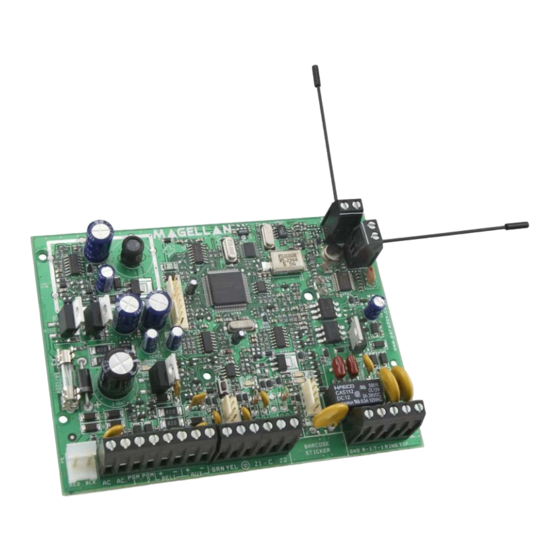
Page 44: Mg5000 Pcb Layout
Charging and MG5000 keypad. Battery test LED Paradox Memory Key (PMC-3, PMC-4) Warning: Disconnect telephone line before servicing. Refer to AC Power & Backup Battery Connections on page 41. -
Page 45: Trouble Display
Trouble Display - Press the [ ] key to view the Trouble Display. Please note that the keypad can be programmed to emit a beep every 5 seconds whenever a new trouble condition has occurred. Press the [ ] key to stop the beeping. - To view the sub-menu, press the corresponding key in the main menu. - Page 46 Warranty Paradox Security Systems Ltd. (“Seller”) warrants its products to be free from defects in materials and workmanship under normal use for a period of one year. Except as specifically stated herein, all express or implied warranties whatsoever, statutory or otherwise, including without limitation, any implied warranty of merchantability and fitness for a particular purpose, are expressly excluded. Because Seller does not install or connect the products and because the products may be used in conjunction with products not manufactured by Seller, Seller cannot guarantee the performance of the security system and shall not be responsible for circumstances resulting from the product’s inability to operate.
- Page 48 Printed in Canada - 12/2006 MG5000-EP04...
Need help?
Do you have a question about the Magellan MG5000 and is the answer not in the manual?
Questions and answers