Multitech MultiVOIP MVP130 User Manual
Voice/fax over ip gateways
Hide thumbs
Also See for MultiVOIP MVP130:
- Supplementary manual (4 pages) ,
- User manual (565 pages) ,
- Configuration manual (79 pages)
Table of Contents
Advertisement
Quick Links
Advertisement
Table of Contents

Related Manuals for Multitech MultiVOIP MVP130


Summary of Contents for Multitech MultiVOIP MVP130
-
Page 1: User Guide
® MultiVOIP Voice/Fax over IP Gateways MVP130 MVP130-FXS User Guide... - Page 2 Furthermore, Multi-Tech Systems, Inc. reserves the right to revise this publication and to make changes from time to time in the content hereof without obligation of Multi-Tech Systems, Inc. to notify any person or organization of such revisions or changes.
-
Page 3: Table Of Contents
Message Waiting... 37 FXO Parameters ... 38 DID Parameters ... 43 Call Signaling... 44 H.323 ... 44 SIP ... 46 SPP... 48 SNMP ... 50 Regional... 51 SMTP... 54 RADIUS ... 57 Logs/Traces ... 59 NAT Traversal... 60 Multi-Tech Systems, Inc. CONTENTS... - Page 4 Identifying Current Firmware Version... 107 Downloading Firmware ... 108 Downloading Factory Defaults ... 109 Downloading IFM Firmware ... 110 Setting and Downloading User Defaults ... 112 Setting a Password ... 113 Windows Interface... 113 Web Browser Interface... 114 Multi-Tech Systems, Inc.
- Page 5 Appendix B – TCP/UDP Port Assignments... 125 Appendix C – Warranty and Repair Policies ... 126 Appendix D – Regulatory Information... 128 Appendix E – Waste Electrical and Electronic Equipment (WEEE) Statement... 130 Appendix F – C-ROHS HT/TS Substance Concentration ... 131 Multi-Tech Systems, Inc.
-
Page 6: Chapter 1 - Description And Specifications
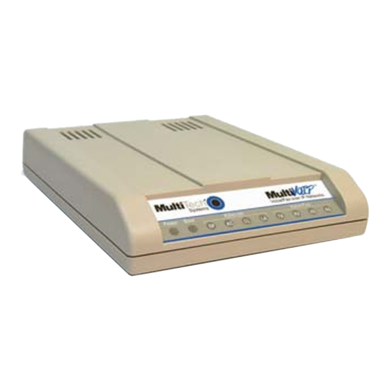
Specifications Introduction The MultiVOIP MVP130 is a single-channel unit and the MVP130FXS is a single-channel unit that supports the FXS telephony interface only. Both of these MultiVOIP units have a 10/100Mbps Ethernet interface and a command port for configuration. The MVP130 and MVP130FXS are table-top models. -
Page 7: Front Panel Leds
Operating Voltage/Current Mains Frequencies Power Consumption Mechanical Dimensions Weight Ambient temperature range Multi-Tech Systems, Inc. Figure 1-2. MVP130/130-FXS LEDs Front Panel LED Definitions MVP130 & MVP130-FXS 100-240VAC / 1.0 A 50/60 Hz 4.5 watts (9.7 watts with phone off hook) 1.0”... -
Page 8: Chapter 2 - Installing And Cabling The Multivoip
When unpacking your MultiVOIP, check to see that all of the items are included in the box. For the various MultiVOIP models, the contents of the box will be different. If any box contents are missing, contact Multi-Tech Tech Support at 1-800-972-2439. -
Page 9: Cabling Procedure For Mvp130
BOOT LED on the MultiVOIP to go off before proceeding. This may take a few minutes. 5. Proceed to the Software Installation chapter to load the MultiVOIP software. Multi-Tech Systems, Inc. Chapter 2: Installing and Cabling the MultiVOIP Figure 2-1: Rear connections for MVP130... -
Page 10: Chapter 3 - Software Installation
2. Insert the MultiVOIP CD into your CD-ROM drive. The CD starts automatically. It may take a few moments for the Multi-Tech CD installation window to display. Figure 3-1: splash screen 3. When the Multi-Tech Installation CD dialog box appears, click the Install Software icon. Multi-Tech Systems, Inc. - Page 11 6. At the next screen, you must select a program folder location for the MultiVOIP software program icon. Click Next. Transient progress screens will appear while files are being copied. Multi-Tech Systems, Inc. Figure 3-2: Initial screen Figure 3-3: Destination...
- Page 12 9. When setup of the MultiVOIP software is complete, you will be prompted to run the MultiVOIP software to configure the VOIP. Software installation is now complete. Multi-Tech Systems, Inc. Figure 3-4: Completion Figure 3-5: Configuration Chapter 3: Software Installation...
-
Page 13: Setup Overview
⇒ Ethernet/IP ⇒ Voice/Fax ⇒ Interface ⇒ Call Signaling ⇒ Regional ⇒ Phone Book This setup process is followed by the Save & Reboot step which is very important. Multi-Tech Systems, Inc. Figure 3-6: Main Screen Chapter 3: Software Installation... -
Page 14: Ethernet/Ip
Setting both values to 0 effectively disables Diff Serv • FTP Server Enable is only needed for firmware and software updates to the MultiVOIP • TDM Routing can be used if necessary Multi-Tech Systems, Inc. Figure 3-7: IP settings Chapter 3: Software Installation... -
Page 15: Voice/Fax
The individual channels must be set up before use. The Copy Channel button can save a lot of time during this step if channels are to be set with the same parameters. Some options should be noted for future changes if necessary, but the defaults are likely to work without adjustment. Figure 3-8: Voice & Fax settings Multi-Tech Systems, Inc. - Page 16 Select any Automatic Disconnection options needed to ensure lines are not left “open” Configurable Payload Types are best left at their defaults. The Copy Channel button is available for easily transferring these settings to the other channels • Repeat for all channels to be used Multi-Tech Systems, Inc. Chapter 3: Software Installation...
-
Page 17: Interface
If too much time elapses between digits, and the wrong numbers are mapped, you will hear rapid busy signal. If this happens, hang up and dial again. Figure 3-9: Interface Parameters Multi-Tech Systems, Inc. - Page 18 Tone Detection (disconnect from termination of tone) • Available Tones • Disconnect Tones (shows current selection from Available Tones) • DID Options (not available for the MVP130-FXS) Start Modes (Immediate, Wink or Delay Dial) Wink Timer (in milliseconds) Multi-Tech Systems, Inc. Chapter 3: Software Installation...
-
Page 19: Call Signaling
There are three choices for Call Signaling: H.323, SIP and SPP. It is best to select one of these as the protocol to be used, rather than mixing them. Single Port Protocol (SPP) is a non-standard protocol created by Multi-Tech that allows dynamic IP allocation. - Page 20 • Enter information for the Primary and Alternate Registrars • Polling Interval (time between connect attempts) Keep Alive (time out for client un-registering) Behind Proxy/NAT device • Enter Public IP of Proxy/NAT server Multi-Tech Systems, Inc. Chapter 3: Software Installation...
-
Page 21: Regional
If there is not a selection to fit your needs, you may select Custom and set the tones manually User Defined tones can be created for use in conjunction with FXO Supervision with the Add button Multi-Tech Systems, Inc. Figure 3-11: Regional Parameters Chapter 3: Software Installation... -
Page 22: Phone Book
Without a populated phone book, the VOIP unit is unable to translate call traffic. You will need the information for both a local and any remote sites that are to be used. Detailed descriptions and examples are available in chapter 5. Figure 3-12: Phone Book screens Multi-Tech Systems, Inc. -
Page 23: Save & Reboot
Save & Reboot Any time that you change settings on the VOIP unit, you must choose the Save & Reboot option; otherwise all changes made will be lost when the MultiVOIP is reset or shutdown. Multi-Tech Systems, Inc. Chapter 3: Software Installation... -
Page 24: Chapter 4 - Configuring Your Multivoip
Phone Book setup and Chapter 6 will discuss the Statistics options and overall maintenance of the MultiVOIP. Software Categories Covered in This Chapter Ethernet/IP Voice/Fax Interface Call Signaling o H.323/SIP/SPP SNMP Regional SMTP RADIUS Logs/Traces NAT Traversal Supplementary services Save Setup Connection o Settings Multi-Tech Systems, Inc. -
Page 25: How To Navigate Through The Software
• Delay Dial Country code Email address for VOIP (optional) Reminder: Be sure to Save Setup Multi-Tech Systems, Inc. Configuration screen where info is entered: Ethernet/IP parameters Interface parameters In FXS/FXO systems, channels used for phone, fax, or key system are FXS; channels used for analog... -
Page 26: Ethernet/Ip
The Ethernet/IP Parameters fields are described in the tables and text passages below. Note that both Diff Serv parameters (Call Control PHB and VOIP Media PHB) must be set to zero if you enable Packet Prioritization (802.1p). Nonzero Diff Serv values negate the prioritization scheme. Multi-Tech Systems, Inc. - Page 27 IP Mask n.n.n.n Gateway n.n.n.n Table is continued on next page… Multi-Tech Systems, Inc. Ethernet/IP Parameter Definitions Description Select to activate prioritization under 802.1p protocol (described below). Must be set to match network’s frame type. Default is Type II. Sets the priority for signaling packets.
- Page 28 Enable SRV DNS Server IP n.n.n.n Address Multi-Tech Systems, Inc. Description Value is used to prioritize call setup IP packets. Setting this parameter to 0, in conjunction with VOIP Media PHB below will disable Diff Serv. Value is used to prioritize the RTP/RTCP audio IP packets.
-
Page 29: Voice/Fax
It is recommended to disable the FAX relay when doing modem bypass for a higher success rate. Figure 4-2: Voice/Fax parameters The Voice/FAX Parameters settings are described in the tables below. Multi-Tech Systems, Inc. - Page 30 The DTMF Gain (Dual Tone Multi-Frequency) controls the volume level of the DTMF tones sent out for Touch-Tone dialing. Default value: -4 dB. Not to be changed except under supervision of Multi-Tech Technical Support. Default value: -7 dB. Not to be changed except under supervision of Multi-Tech Technical Support.
- Page 31 Cancellation Forward Error Correction Table is continued on next page… Multi-Tech Systems, Inc. Voice/Fax Parameter Definitions (continued) Determines whether selection of coder is manual or automatic. When Automatic is selected, the local and remote voice channels will negotiate the voice coder to be used by selecting the highest bandwidth coder supported by both sides without exceeding the Max Bandwidth setting.
- Page 32 0 – 3000 seconds Phone Number Table is continued on next page… Multi-Tech Systems, Inc. Voice/Fax Parameter Definitions (continued) Description The AutoCall option enables the local MultiVOIP to call a remote MultiVOIP without the user having to dial a Phone Directory Database number. As soon as...
-
Page 33: Configurable Payload Type
Whenever you interoperate with older MultiVOIP products (i.e., earlier than release n.11), for backward compatibility, make sure to configure the payload type values to default ones, which match the values of older MultiVOIP’s. Multi-Tech Systems, Inc. Voice/Fax Parameter Definitions (continued) Description Dynamic Jitter defines a minimum and a maximum jitter value for voice communications. -
Page 34: Interface
In each field, enter the values that fit your particular setup. The screen below shows more options available than are actually used for clarity. Your settings will determine what fields are available. Figure 4-3: Telephony parameters Multi-Tech Systems, Inc. -
Page 35: Fxs Loop Start Parameters
1-99 Current Loss Generate Current Reversal Table is continued on next page… Multi-Tech Systems, Inc. Figure 4-4: FXS Loop Start parameters FXS Loop Start Interface: Parameter Definitions Description Enables FXS Loop Start interface type. This is the length of time that the MultiVOIP will wait between digits. - Page 36 CID Mode Transparent, User CID, Prefix, Suffix Multi-Tech Systems, Inc. Chapter 4: Configuring your VOIP Description Not applicable to FXS interface For a received flash hook to be regarded as such by the MultiVOIP, its duration must fall between the minimum and maximum values given...
-
Page 37: Message Waiting
(i.e., if the MultiVOIP gets a 401/407 response from a subscribe request. Then it will take the configured password, calculate the response, and resend the “SUBSCRIBE” request. Multi-Tech Systems, Inc. Figure 4-5: Message Waiting Chapter 4: Configuring your VOIP... -
Page 38: Fxo Parameters
Chapter 4: Configuring your VOIP FXO Parameters The parameters applicable to the FXO telephony interface type are shown in the figure below and described in the table that follows. Figure 4-6: FXO parameters Multi-Tech Systems, Inc. - Page 39 Disable CID Mode Transparent, User CID, Prefix, Suffix Multi-Tech Systems, Inc. FXO Interface: Parameter Definitions Description Enables FXO functionality Determines whether digits generated and sent out will be pulse tones or DTMF. This is the length of time that the MultiVOIP will wait between digits.
- Page 40 When the selected Interface type is FXO, the Supervision button is active. Click on this button to access call answering supervision parameters and call disconnection parameters that relate to the FXO interface type. Figure 4-7: FXO Supervision The table below describes the settings for FXO Supervision. Multi-Tech Systems, Inc.
- Page 41 Silence Timer in integer value seconds Table is continued on next page… Multi-Tech Systems, Inc. FXO Supervision Parameter Definitions Description When this option is selected, the FXO interface sends notice to make connection upon detecting current reversal from the PBX (which occurs when the called extension goes off hook).
- Page 42 (fast busy), survivability tone, re-order tone Disconnect any tone from Tones Available Tones list Multi-Tech Systems, Inc. Chapter 4: Configuring your VOIP Description Enables supervision of call disconnection using DTMF tones. 1336Hz 1447Hz These are DTMF tone pairs. Values for first tone pair are: *, #, 0, 1-9, and A-D.
-
Page 43: Did Parameters
Indication Inter-Digit Integer values, Regeneration in milliseconds Timer Multi-Tech Systems, Inc. Figure 4-8: DID parameters DID Interface Parameter Definitions Description Enables the customer-premises side of DID functionality MultiVOIP’s use of DID applies only for incoming DID calls. The Start Mode used by the MultiVOIP must match that used by the originating telephony equipment;... -
Page 44: H.323
H.323 H.323 is an ITU-T recommended set of standards for audio and video communications. The fields for this screen are defined in the table below. Multi-Tech Systems, Inc. Figure 4-9: H.323 call signaling Chapter 4: Configuring your VOIP... - Page 45 H.245 Tunneling (Tun) Parallel H.245 (FS + Tun) Annex –E (AE) Multi-Tech Systems, Inc. H.323 Call Signaling Parameter Definitions. Description Enables the H.323 Fast Start procedure. May need to be enabled / disabled for compatibility with third-party VOIP gateways. Default: 1720 (H.323) Check this field to have traffic on current VOIP gateway controlled by a gatekeeper.
-
Page 46: Sip
Chapter 4: Configuring your VOIP Session Initiation Protocol is the second option available for application layer control of the MultiVOIP. The fields are detailed in the table below. Figure 4-10: SIP call signaling Multi-Tech Systems, Inc. - Page 47 SIP proxy “Time to Live” value. seconds) Multi-Tech Systems, Inc. SIP Call Signaling Parameter Definitions Description Port number on which the MultiVOIP UserAgent software module will be waiting for any incoming SIP requests. Default = 5060 Allows the MultiVOIP to work in conjunction with a proxy server.
-
Page 48: Spp
Chapter 4: Configuring your VOIP Single Port Protocol was developed by Multi-Tech to allow for dynamic IP addressing when it is set to Registrar/Client mode. The other choice, Direct mode, has IP addresses assigned to the gateways. The table below describes all fields in the general SPP Call Signaling screen. - Page 49 Device Parameters – Public IP Address Multi-Tech Systems, Inc. SPP Call Signaling Parameter Definitions Description In direct mode, all VOIP gateways have static IP addresses assigned to them. In registrar/client mode, one VOIP gateway serves as registrar and all other gateways, being its clients, point to that registrar.
-
Page 50: Snmp
MultiVoipManager software, check the “Enable SNMP Agent” box on the SNMP Parameters screen. The MVP130 MultiVOIPs only have limited SNMP functionality available. If this is something you wish to use, please contact Multi-Tech Support for assistance. The SNMP Parameter fields are described in the table below. -
Page 51: Regional
If you need settings that are not available, the Custom selection will let you set the tones to what is necessary. The Regional Parameters fields are described in the table below. Figure 4-13: Regional parameters Multi-Tech Systems, Inc. - Page 52 Custom (button) Table is continued on next page… Multi-Tech Systems, Inc. “Regional Parameter” Definitions Description Name of a country or region that uses a certain set of tone pairs for dial tone, ring tone, busy tone, unobtainable tone (fast busy tone), survivability tone (tone...
- Page 53 Cadence 3 duration in milliseconds Cadence 4 duration in milliseconds Multi-Tech Systems, Inc. Description MultiVOIP units operating with the X.06 software release (and above) include a built-in modem. The administrator can dial into this modem to configure the MultiVOIP unit remotely. The country name values in this field set telephony parameters that allow the modem to work in the listed country.
-
Page 54: Smtp
MultiVOIP or both, and the VOIP administrator might also be designated as the “Reply-To” party. The main function of the Reply-To address is to receive error or failure messages regarding the emailed reports. The SMTP Parameters screen is shown below: Figure 4-14: SMTP parameters Multi-Tech Systems, Inc. - Page 55 Number of Records integer Number of Days integer Multi-Tech Systems, Inc. “SMTP Parameters” Definitions Description In order to send log reports by email, this box must be checked. However, to enable SMTP functionality, you must also select “SMTP” in the Logs screen.
- Page 56 IP address where call originated. Descript Identifier of site where call originated. Options When selected, log will not Silence Compression and Forward Error Correction by call originator. Multi-Tech Systems, Inc. “Custom Fields” Definitions Field Start Date, Time Call Mode Packets...
-
Page 57: Radius
The accounting function is well suited for billing of VOIP telephony services. In the Select Attributes secondary screen (accessed by clicking on Select Attributes button), the VOIP administrator can select the parameters to be tallied by the RADIUS server. Figure 4-15: RADIUS settings Multi-Tech Systems, Inc. - Page 58 Identifier of where call originated. Options When selected, log will not use Silence Compression and Forward Error Correction by call originator. Multi-Tech Systems, Inc. RADIUS Screen Field Definitions Description When checked, the MultiVOIP will access the accounting functionality of the RADIUS server.
-
Page 59: Logs/Traces
Logical port for SysLog Server. 514 is commonly used. Online Statistics integer Set the interval (in seconds) at which logging information will be updated. Updation Interval Multi-Tech Systems, Inc. Figure 4-16: Logs and Filters screens “Logs” Screen Definitions Chapter 4: Configuring your VOIP... -
Page 60: Nat Traversal
3478 Keep Alive (Timers; 60 – 3600 NAT/STUN) (seconds) Multi-Tech Systems, Inc. Figure 4-17: NAT Traversal NAT Traversal Definitions Description Enables STUN client functionality in the MultiVOIP. STUN (Simple Traversal of UDP through NATs (Network Address Translation)) is a protocol that allows a server to assist client gateways behind a NAT firewall or router with their packet routing. -
Page 61: Supplementary Services
(for example, “Busy Party - Omaha Sales Office Line 2”). These messages appear in the Statistics – Call Progress screen of the remote VOIP. Figure 4-18: Supplementary Services The Supplementary Services fields are described in the tables below. Multi-Tech Systems, Inc. - Page 62 CNI messages; in other VOIP brands, H.450 may be implemented differently and then the message presentation may vary.) Table is continued on next page… Multi-Tech Systems, Inc. Chapter 4: Configuring your VOIP Description The channel to be configured is selected here.
- Page 63 When this button is clicked, all Supplementary Service parameters are set to their default values. Copy Channel Copies the Supplementary Service attributes of one channel to another channel. Attributes can be copied to multiple channels or all channels at once. Multi-Tech Systems, Inc. Chapter 4: Configuring your VOIP...
-
Page 64: Save Settings
COM port assignments in the system resource manager of your Windows operating system. If COM1 is not available, you must change the COM port setting to a COM port that you have confirmed as being available on your PC. Multi-Tech Systems, Inc. Figure 4-19: COM port setup Chapter 4: Configuring your VOIP... -
Page 65: Troubleshooting Software Issues
Not Found”, “Phone Database Not Read” and “Password Phone Database Not Read). Figure 4-21: Cabling errors In this case, the MultiVOIP is simply disconnected from the network. For instructions on MultiVOIP cable connections, see the Cabling section of Chapter 3. Multi-Tech Systems, Inc. -
Page 66: Chapter 5 - Phone Book Configuration
VOIP protocol for all VOIP units in the system. SPP is a non- standard protocol developed by Multi-Tech. SPP is not compatible with the “Proprietary” protocol used in Multi- Tech’s earlier generation of VOIP gateways. -
Page 67: Phonebook Starter Configuration
“8” for all VOIP calls. “1” must immediately precede area code of dialed number. : write down 81. Answer Multi-Tech Systems, Inc. Euro, National Call Example Technician in central London (area 0207) to set up VOIP there, another in Birmingham (area 0121). - Page 68 7. In the “Protocol Type” field group, select the VOIP protocol that you will use (H.323, SIP, or SPP). Use the appropriate screen under Configuration | Call Signaling to configure the VOIP protocol in detail. 8. Click OK to exit from the Add/Edit Outbound Phonebook screen. Multi-Tech Systems, Inc. Chapter 5: Phonebook Configuration Euro, National Call Example London/Birmingham system.
-
Page 69: Inbound Phonebook
8. Click OK to exit the inbound phonebook screen. 9. Click on Save Setup. Highlight Save and Reboot. Click OK. Your starter inbound phonebook configuration is complete. Multi-Tech Systems, Inc. Chapter 5: Phonebook Configuration Euro, National Call Example London/Birmingham system. -
Page 70: Phone Book Descriptions
Phone Book Descriptions Outbound Phone Book/List Entries Fields in the “Details” section will differ depending on the protocol (H.323, SIP, or SPP) of the selected list entry to which the details pertain. Figure 5-1: Outbound Phone Book Multi-Tech Systems, Inc. -
Page 71: Add/Edit Outbound Phone Book
Alternate IP Routing feature, if needed. Alternate IP Routing can be implemented in a secondary screen (as described after the primary screen field definitions below). The fields of the Add/Edit Outbound Phone Book screen are described in the table below. Multi-Tech Systems, Inc. - Page 72 Describes the facility or geographical location at which the call will be completed. Indicates protocol to be used in outbound transmission. Single Port Protocol (SPP) is a non-standard protocol designed by Multi-Tech. Indicates whether or not gatekeeper is used. The H.323 ID assigned to the destination MultiVOIP. Only valid if “Use Gatekeeper”...
- Page 73 Gives access to secondary screen where an Alternate IP Route can be specified for backup or button redundancy of signal paths. For SIP & H.323 operation only. Multi-Tech Systems, Inc. Chapter 5: Phonebook Configuration Description Select if proxy server is used.
- Page 74 PSTN Failover Feature network fails. See Figure 5-4 below for example. 3. Call diverts to Alt IP address in voip accessing PSTN line. 1. Call originates. Multi-Tech Systems, Inc. Figure 5-3: Advanced button Alternate Routing Field Definitions PSTN Line VOIP VOIP NETWORK 2.
-
Page 75: Inbound Phone Book/List Entries
Inbound Phone Book/List Entries The “Details” and “Registration Options” sections will display information based on the setup and protocols chosen. The “Subscription Options” area is used in conjunction with a Voice Mail Server. Figure 5-5: Inbound phonebook entries Multi-Tech Systems, Inc. -
Page 76: Add/Edit Inbound Phone Book
Chapter 5: Phonebook Configuration Add/Edit Inbound Phone Book Figure 5-6: Add/Edit Inbound Phone Book Multi-Tech Systems, Inc. - Page 77 In a SIP VOIP system, gateways can register with the SIP Proxy. In an SPP VOIP system, gateways can register with the SPP Registrar VOIP unit. Multi-Tech Systems, Inc. Description When checked, “Any Number” appears as the value in the Remove Prefix field.
-
Page 78: Phone Book Save And Reboot
Configuration/Command Modem using the MultiVOIP program. After the initial configuration is complete, all of the MultiVOIP units in the VOIP system can be configured, re-configured, and updated from one location using the MultiVOIP web interface software program or the MultiVOIP program (in conjunction with the built-in modem). Multi-Tech Systems, Inc. Chapter 5: Phonebook Configuration... -
Page 79: Phonebook Examples
Baltimore’s local calling area consists of a base area code plus an overlay area code. Company VOIP/PBX SIte Suburbs SW Suburbs An outline of the equipment setup in both offices is shown below. Multi-Tech Systems, Inc. St. Paul Mpls & Suburbs Company VOIP/PBX Figure 5-7: North America example... - Page 80 PBX is actually located -- 763). A similar sequence of events occurs when the Baltimore employee calls number in the 651 and 952 area codes because number in both of these area codes are local calls in the Minneapolis/St. Paul area. Multi-Tech Systems, Inc.
- Page 81 The Outbound Phone Book for the Minneapolis VOIP is shown below. The third destination pattern, “7” facilitates reception of co-worker calls using local-appearing-extensions only. In this case, the “Add Prefix” field value for this phonebook entry would be “1410325”. Figure 5-12: Outbound Minneapolis example Multi-Tech Systems, Inc.
-
Page 82: Europe
Wren Clothing Co. Wren Clothing Co. VOIP/PBX Site Bluebird Zipper Co. London VOIP/PBX Site London Amsterdam Netherlands Wren Clothing Co. Calls at London local rates VOIP/PBX Site Paris Local Calling Area France Figure 5-14: Local calling area Multi-Tech Systems, Inc. -
Page 83: Country Code
Vendors in Guildford, Lyon, and Rotterdam can be contacted as national calls by all company offices. The Netherlands Country Code: 31 Den Helder 0223 Haarlem 023 The Hague 0118 Middelburg Multi-Tech Systems, Inc. Figure 5-15: UK & France codes Leeuwarden Texel 0222 038 Zwolle 0299 Purmerend Beverwijk 0251 020 Amsterdam... - Page 84 Chapter 5: Phonebook Configuration An outline of the equipment setup in these three offices is shown below. Figure 5-17: Setup example Multi-Tech Systems, Inc.
- Page 85 Figure 5-19: London example inbound NOTE: Commas are allowed in the Inbound Phonebook, but not in the Outbound Phonebook. Commas denote a brief pause for a dial tone, allowing time for the PBX to get an outside line. Multi-Tech Systems, Inc.
- Page 86 The screen below shows Outbound Phone Book entries for the VOIP located in the company’s Paris facility. Figure 5-20: Paris example outbound The Inbound Phone Book for the Paris VOIP is shown below. Figure 5-21: Paris example inbound Multi-Tech Systems, Inc.
- Page 87 The screen below shows Outbound Phone Book entries for the VOIP in the company’s Amsterdam facility. Figure 5-22: Amsterdam example outbound The Inbound Phone Book for the Amsterdam VOIP is shown below. Figure 5-23: Amsterdam example inbound Multi-Tech Systems, Inc.
-
Page 88: Variations Of Caller Id
In x.06 release, when SIP protocol is used, CID Name field will duplicate value in CID Number field. Figure 5-26: VOIP Caller ID Case #2 – Call, through telco central office without standard CID, enters H.323 VOIP system. Multi-Tech Systems, Inc. CID Flow Generating VoIP Network H.323 or SPP... - Page 89 In x.06 release, when SIP protocol is used, CID Name field will duplicate value in CID Number field. Figure 5-28: VOIP Caller ID Case #4 – Remote FXS call on H.323 VOIP system. Multi-Tech Systems, Inc. CID Flow Central Office Generating...
- Page 90 CID Name field will duplicate value in CID Number field. Figure 5-29: VOIP Caller ID Case #5 – Call through telco central office without standard CID enters DID channel in H.323 VOIP system. Multi-Tech Systems, Inc. CID Flow Generating VoIP...
-
Page 91: Chapter 6 - Using The Software
Software Categories Covered in This Chapter System Information Call Progress Logs IP Statistics Link Management Registered Gateway Details Servers o H.323 GateKeepers o SIP Proxies o SPP Registrars Advanced o Packetization Time Multi-Tech Systems, Inc. -
Page 92: System Information Screen
Hardware ID alpha- numeric Multi-Tech Systems, Inc. Figure 6-1: System information System Information Parameter Definitions Description Indicates the version of the code that is used at the startup (booting) of the VOIP. The boot code version is independent of the software version. -
Page 93: Statistics Section
Statistics functions of the MultiVOIP software. The following screens are examples of what can be shown and are followed by detailed descriptions of the categories involved. The model and signaling used will affect what is available for display. Call Progress Figure 6-3: Call progress screen Multi-Tech Systems, Inc. - Page 94 (H.323, SIP, or SPP). Table is continued on next page… Multi-Tech Systems, Inc. Call Progress Details: Field Definitions Description Number of data channel or time slot on which the call is carried. This is the channel for which call-progress details are being viewed.
-
Page 95: Logs
AE, Mux Silence Compression Forward Error Correction Logs Multi-Tech Systems, Inc. Description Describes held call by its IP address source, location/gateway identifier, and hold duration. Location/gateway identifiers come from Gateway Name field in Phone Book Configuration screen of remote VOIP. - Page 96 Supplementary Services Info Call Transferred To phone number Call Forwarded To phone number Multi-Tech Systems, Inc. Logs Screen Details: Field Definitions Description All calls are assigned an event number in chronological order, with the most recent call having the highest event number.
-
Page 97: Ip Statistics
In certain applications, like audio and video data transmission, the need for high speed outweighs the need for verified data integrity. Sound or pictures often remain intelligible despite a certain amount of lost or disordered data packets (which comes through as static). Multi-Tech Systems, Inc. - Page 98 Received with integer Number of error-laden RTCP packets received by this VOIP gateway since the last Errors value “clearing” or resetting of the counter within the MultiVOIP software. Multi-Tech Systems, Inc. IP Statistics: Field Definitions Chapter 6: Using the Software...
-
Page 99: Link Management
(Min/Max/Avg) in milliseconds Last Error as listed Multi-Tech Systems, Inc. Figure 6-6: Link management Link Management screen Field Definitions Description This is the IP address of the target endpoint to be pinged. This field determines how many pings will be generated by the Start Now command. -
Page 100: Registered Gateway Details
Registered Numbers List of Registered Numbers Multi-Tech Systems, Inc. Figure 6-7: Registered endpoints Description This is a descriptor for a particular VOIP gateway unit. This descriptor should generally identify the physical location of the unit (e.g., city, building, etc.) and perhaps even its location in an equipment rack. -
Page 101: Servers
Type Primary, Predefined Priority Status registered, not registered Multi-Tech Systems, Inc. Figure 6-8: H.323 Gatekeepers Description The IP address of the gatekeeper. TDMA time slot used for communication between MultiVOIP unit and the gatekeeper that serves it. Identifier for gatekeeper... -
Page 102: Sip Proxies
Primary, Alternate Status registered, not registered Multi-Tech Systems, Inc. Figure 6-9: SIP proxies SIP Proxies (Statistics, Servers): Field Definitions Description The IP address of the SIP proxy by which the MultiVOIP is governed. TDMA time slot used for communication between MultiVOIP unit and the SIP Proxy that governs it. -
Page 103: Spp Registrars
Type Primary, Predefined Status registered, not registered Multi-Tech Systems, Inc. Figure 6-10: SPP registrars Description The IP address of the gatekeeper. TDMA time slot used for communication between MultiVOIP unit and the gatekeeper that serves it. This field describes the type of gateway as which the MultiVOIP is defined with respect to the gatekeeper. -
Page 104: Advanced
Once the packetization rate has been set for one channel, it can be copied into other channels by using the Copy Channel button on the Packetization Time screen. Simply click the boxes next to the channels you wish to copy the settings for. Multi-Tech Systems, Inc. Figure 6-11: Packetization time Increments (in Kbps) -
Page 105: Multivoip Program Menu Items
Download Firmware Download IFM Firmware Download User Defaults Set Password Uninstall Upgrade Software Multi-Tech Systems, Inc. Figure 6-12: Program menu MultiVOIP Program Menu Description Select this to enter the Configuration program where values for IP, telephony, and other parameters are set. -
Page 106: Updating Firmware
(from the perspective of the PC), this type of download cannot be initiated from the MultiVOIP software’s Program menu command set. Generally, updated firmware must be downloaded from the Multi-Tech website to the PC before it can be loaded from the PC to the MultiVOIP. -
Page 107: Implementing A Software Upgrade
MultiVOIP. Download Factory Defaults sets all configuration parameters to the standard default values that are loaded at the Multi-Tech factory. Upgrade Software implements both the Download Firmware command and the Download Factory Defaults command. -
Page 108: Downloading Firmware
6. Progress bars will appear at the bottom of the screen during the file transfer. The MultiVOIP’s “Boot” LED will turn off at the end of the transfer. 7. The Download Firmware procedure is complete. Multi-Tech Systems, Inc. Figure 6-15: Password verification Figure 6-16: Firmware file... -
Page 109: Downloading Factory Defaults
6. Progress bars will appear at the bottom of the screen during the data transfer. The MultiVOIP’s “Boot” LED will turn off at the end of the transfer. 7. The Download Factory Defaults procedure is complete. Multi-Tech Systems, Inc. Figure 6-18: Password verify Figure 6-19: Dialog screen... -
Page 110: Downloading Ifm Firmware
7. The IFM Firmware Download screen will appear. Select “Copy to All IFMs” and click OK. (Only in very special circumstances would different IFMs in the same VOIP be loaded with different IFM firmware.) Multi-Tech Systems, Inc. Figure 6-21: Download IFM firmware... - Page 111 Click OK. 10. The MultiVOIP will reboot itself. When the reboot is complete, the MultiVOIP Configuration screen will close. 11. The IFM firmware downloading process is complete. Multi-Tech Systems, Inc. Figure 6-23: IFM firmware download Figure 6-24: IFM test screen...
-
Page 112: Setting And Downloading User Defaults
6. When the file transfer process is complete, the Dialog / IP Parameters screen will appear. 7. Set the IP values per your particular VOIP system. Click OK. Progress bars will appear as the MultiVOIP reboots itself. Multi-Tech Systems, Inc. Figure 6-25: Save & Reboot MultiVOIP n.nn... -
Page 113: Setting A Password
NOTE: Record your user name and password in a safe place. If the password is lost, forgotten, or irretrievable, the user must contact Multi-Tech Tech Support in order to resume use of the MultiVOIP unit. 1. The MultiVOIP configuration program must be off when invoking the Set Password command. If it is on, the command will not work. -
Page 114: Web Browser Interface
MultiVOIP web browser interface. NOTE: Record your user name and password in a safe place. If the password is lost, forgotten, or irretrievable, the user must contact Multi-Tech Tech Support in order to resume use of the MultiVOIP web browser interface. -
Page 115: Upgrading Software
C:\Program Files\Multi-Tech Systems\MultiVOIP X.NN where the X is the software number and the .NN is the version number of the MultiVOIP software on your local drive. Of course the firmware file is named ‘mvpt1ftp.bin’. -
Page 116: Ftp Server File Transfers ("Downloads")
FTP Server File Transfers (“Downloads”) Multi-Tech has built an FTP server into the MultiVOIP unit. Therefore, file transfers from the controller PC to the VOIP unit can be done using an FTP client program or even using a browser (e.g., Internet Explorer, Netscape, or Firefox, used in conjunction with Windows Explorer). - Page 117 With an FTP client program, multiple VOIPs can receive FTP file transmissions in response to a single command (the transfers may occur serially however). Although Multi-Tech does not provide an FTP client program with the MultiVOIP software or endorse any particular FTP client program, we remind our readers that adequate FTP programs are readily available under retail, shareware and freeware licenses.
- Page 118 FTP file transfer is to be done with a web browser (shown below) or with an FTP client program (varies). 8. Use Download. Downloading can be done with a web browser or with an FTP client program. Multi-Tech Systems, Inc. File Names Description mvpt1Ftp.bin...
- Page 119 Download with Web Browser: • In the local Windows browser, locate the directory holding the MultiVOIP program files. The default location will be C:\Program Files \Multi-Tech Systems \MultiVOIP xxxx yyyy (where x and y represent MultiVOIP model numbers and software version numbers).
- Page 120 • In the local directory browser of the FTP client program, locate the directory holding the MultiVOIP program files. The default location will be C:\Program Files \Multi-Tech Systems \MultiVOIP xxxx yyyy (where x and y represent MultiVOIP model numbers and software version numbers).
-
Page 121: Web Browser Interface
To install the Java program, go to the Java directory on the MultiVOIP product CD. Double-click on the .EXE file to begin the installation. Follow the instructions on the Install Shield screens. Multi-Tech Systems, Inc. Figure 6-42: Web interface main page MultiVOIP Web Browser interface Overview Remote configuration and control of MultiVOIP units. - Page 122 Windows interface. As noted earlier, logging functions cannot be handled via the web interface. And, because network communications will be slower than direct communications over a serial PC cable, command execution will be somewhat slower over the web browser interface than with the Windows interface. Multi-Tech Systems, Inc.
-
Page 123: Syslog Server Functions
Chapter 6: Using the Software SysLog Server Functions Multi-Tech has built SysLog server functionality into the software of the MultiVOIP units. SysLog is a de facto standard for logging events in network communication systems. The SysLog Server resides in the MultiVOIP unit itself. To implement this functionality, you will need a SysLog client program (sometimes referred to as a “daemon”). -
Page 124: Appendix A - Cable Pin-Outs
The functions of the individual conductors of the MultiVOIP’s Ethernet port are shown on a pin-by-pin basis below. RJ-45 Ethernet Connector Voice/Fax Channel Connectors Pin Functions (FXS/FXO Interface) RJ-11 FXS Pin Multi-Tech Systems, Inc. End-to-End Pin Info Circuit Signal Name TD+ Data Transmit Positive TD- Data Transmit Negative... -
Page 125: Appendix B - Tcp/Udp Port Assignments
IANA is 0-1023.” Well-known port numbers especially pertinent to MultiVOIP operation are listed below. Port Number Assignment List Function telnet tftp snmp snmp tray gatekeeper registration H.323 SysLog Multi-Tech Systems, Inc. Assignments Port Number 1719 1720 5060... -
Page 126: Appendix C - Warranty And Repair Policies
Multi-Tech Warranty Statement Multi-Tech Systems, Inc., (hereafter “MTS”) warrants that its products will be free from defects in material or workmanship for a period of two, five, or ten years (depending on model) from date of purchase, or if proof of purchase is not provided, two, five, or ten years (depending on model) from date of shipment. - Page 127 Your original point-of-purchase Reseller may offer the quickest and most economical repair option for your Multi- Tech product. You may also contact any Multi-Tech sales office for information about the nearest distributor or other repair service for your Multi-Tech product. The Multi-Tech sales office directory is available at www.multitech.com/PARTNERS/Channels/offices/...
-
Page 128: Appendix D - Regulatory Information
(2) This device must accept any interference that may cause undesired operation. Warning: Changes or modifications to this unit not expressly approved by the party responsible for compliance could void the user’s authority to operate the equipment. Multi-Tech Systems, Inc. -
Page 129: Fcc Part 68 Telecom
No repairs are to be made by you. Repairs are to be made only by Multi-Tech Systems or its licensees. Unauthorized repairs void registration and warranty. -
Page 130: Appendix E - Waste Electrical And Electronic Equipment (Weee) Statement
Substances) complements the WEEE Directive by banning the presence of specific hazardous substances in the products at the design phase. The WEEE Directive covers all Multi-Tech products imported into the EU as of August 13, 2005. EU-based manufacturers, distributors, retailers and importers are obliged to finance the costs of recovery from municipal collection points, reuse, and recycling of specified percentages per the WEEE requirements. -
Page 131: Appendix F - C-Rohs Ht/Ts Substance Concentration
Appendix F – C-ROHS HT/TS Substance 依照中国标准的有毒有害物质信息 根据中华人民共和国信息产业部 (MII) 制定的电子信息产品 (EIP) 标准-中华人民共和国《电子信息产品污染控制管理办法》(第 39 号),也称作中国 RoHS,下表列出了 Multi-Tech Systems Inc. 产品中可能含有的有毒物质 (TS) 或有害物质 (HS) 的名称及含量水平方面的信息。 成分名称 印刷电路板 电阻器 电容器 铁氧体磁环 继电器 / 光学部件 二极管 / 晶体管 振荡器和晶振 调节器 电压传感器 变压器 扬声器 连接器...
Need help?
Do you have a question about the MultiVOIP MVP130 and is the answer not in the manual?
Questions and answers