Table of Contents
Advertisement
Quick Links
Freescale Semiconductor, Inc.
User's Guide
FRDM-KW24D512 Freescale Freedom
Development Board
User's Guide
1
Introduction
This manual describes the Freescale development board,
FRDM-KW24D512, part of the Freescale Freedom
development platform. It has a diverse reference design with
all necessary I/O connections to use as a self-contained
board or for connection to an external application.
The MKW24D512 is a 2.4 GHz Industrial, Scientific, and
Medical (ISM) single-chip device intended for the IEEE
Std. 802.15.4, including Thread, Zigbee Pro, ZigBee RF4CE
and IPv6/6loWPAN protocols.
The FRDM-KW24D512 contains the MKW24D512
transceiver that is combined with a software stack to
implement an IEEE Std. 802.15.4 platform solutions.
1.1
Audience
This manual is intended for system designers.
© 2015 Freescale Semiconductor, Inc. All rights reserved.
Document Number: FRDMKW24DUG
1. Introduction . . . . . . . . . . . . . . . . . . . . . . . . . . . . . . . . 1
1.1.Audience . . . . . . . . . . . . . . . . . . . . . . . . . . . . . . . . 1
2. Safety information . . . . . . . . . . . . . . . . . . . . . . . . . . . 2
2.1.FCC guidelines . . . . . . . . . . . . . . . . . . . . . . . . . . . 2
2.3.Electrostatic discharge considerations . . . . . . . . . . 3
2.4.Disposal instructions . . . . . . . . . . . . . . . . . . . . . . . 3
3. FRDM-KW24D512 overview and description . . . . . 4
3.1.Introduction . . . . . . . . . . . . . . . . . . . . . . . . . . . . . . 4
3.2.Board features . . . . . . . . . . . . . . . . . . . . . . . . . . . . 4
®
3.3.Software and driver considerations . . . . . . . . . . . . 6
4. FRDM-KW24D512 development board . . . . . . . . . . 6
4.1.FRDM-KW24D512 board overview . . . . . . . . . . . 6
4.2.Functional description . . . . . . . . . . . . . . . . . . . . . 10
5. PCB manufacturing specifications . . . . . . . . . . . . . . 27
5.1.Single PCB construction . . . . . . . . . . . . . . . . . . . 28
5.2.Panelization . . . . . . . . . . . . . . . . . . . . . . . . . . . . . 29
5.3.Materials . . . . . . . . . . . . . . . . . . . . . . . . . . . . . . . 29
5.4.Solder mask . . . . . . . . . . . . . . . . . . . . . . . . . . . . . 29
5.5.Silk screen . . . . . . . . . . . . . . . . . . . . . . . . . . . . . . 29
5.6.Electrical PCB testing . . . . . . . . . . . . . . . . . . . . . 29
5.7.Packaging . . . . . . . . . . . . . . . . . . . . . . . . . . . . . . 30
5.8.Hole specification/tool table . . . . . . . . . . . . . . . . 30
5.9.File description . . . . . . . . . . . . . . . . . . . . . . . . . . 30
6. Revision history . . . . . . . . . . . . . . . . . . . . . . . . . . . . 30
Rev. 0, 10/2015
Contents
Advertisement
Table of Contents

Related Manuals for Freescale Semiconductor Freedom FRDM-KW24D512


Summary of Contents for Freescale Semiconductor Freedom FRDM-KW24D512
-
Page 1: Table Of Contents
6. Revision history ......30 © 2015 Freescale Semiconductor, Inc. All rights reserved. -
Page 2: Safety Information
However, the installer is responsible for ensuring that the proper antenna is employed so that the limits in this Part are not exceeded. Freescale Freedom Development Board FRDM-KW24D512 User’s Guide, Rev. 0, 10/2015 Freescale Semiconductor, Inc. -
Page 3: Regulatory Approval For Canada (Ic Rss 210)
Static control packaging and transportation materials and environmental systems Disposal instructions This product may be subject to special disposal requirements. For product disposal instructions, refer to freescale.com/productdisposal. Freescale Freedom Development Board FRDM-KW24D512 User’s Guide, Rev. 0, 10/2015 Freescale Semiconductor, Inc. -
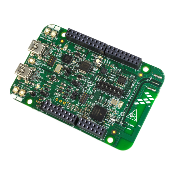
Page 4: Frdm-Kw24D512 Overview And Description
Freedom development boards. Figure 1 shows the FRDM-KW24D512 development board. Freescale Freedom Development Board FRDM-KW24D512 User’s Guide, Rev. 0, 10/2015 Freescale Semiconductor, Inc. - Page 5 Cortex 10-pin (0.05 inches) SWD debug port for target MCU • Cortex 10-pin (0.05 inches) JTAG port for OpenSDA updates • 1 RGB LED indicator • 1 Blue LED indicator • 4 Push button switches Freescale Freedom Development Board FRDM-KW24D512 User’s Guide, Rev. 0, 10/2015 Freescale Semiconductor, Inc.
-
Page 6: Software And Driver Considerations
FRDM-KW24D512 board overview The FRDM-KW24D512 is an evaluation board based on the Freescale MKW24D512 transceiver. The FRDM-KW24D512 board provides a platform to evaluate the MKW24D512 transceiver, develop Freescale Freedom Development Board FRDM-KW24D512 User’s Guide, Rev. 0, 10/2015 Freescale Semiconductor, Inc. - Page 7 External serial flash for OTAP support • Combo sensor, 6-axis sensor with integrated linear accelerometer and magnetometer 4.1.2 Form factor Figure 3 shows the FRDM-KW24D512 board’s connector and header locations. Freescale Freedom Development Board FRDM-KW24D512 User’s Guide, Rev. 0, 10/2015 Freescale Semiconductor, Inc.
- Page 8 — J38 and J39 are adjacent to allow SPI0 data direction to be reversed by altering the orientation of the shunt — J40 and J41 are adjacent to allow UART1 data direction to be reversed by altering the orientation of the shunt Freescale Freedom Development Board FRDM-KW24D512 User’s Guide, Rev. 0, 10/2015 Freescale Semiconductor, Inc.
- Page 9 Operating temperature (see note) °C Operating temperature is limited to +70 °C due to switches. Basic circuit is good for a maximum temperature of +85 °C. Storage temperature °C — Freescale Freedom Development Board FRDM-KW24D512 User’s Guide, Rev. 0, 10/2015 Freescale Semiconductor, Inc.
-
Page 10: Functional Description
LGA package. The MKW24D512 device features a IEEE Std. 802.15.4 radio frequency transceiver and a Kinetis family low-power, mixed-signal ARM Cortex-M4 MCU in a single package. The Freescale Freedom Development Board FRDM-KW24D512 User’s Guide, Rev. 0, 10/2015 Freescale Semiconductor, Inc. - Page 11 RF circuitry. A footprint is available to install the RF connector J48 for measurement purposes. When using J48, C17 must be installed and C18 removed. Freescale Freedom Development Board FRDM-KW24D512 User’s Guide, Rev. 0, 10/2015 Freescale Semiconductor, Inc.
- Page 12 — Load capacitors C23 and C24 provide the entire crystal load capacitance; there is no onboard trim capacitance. — The 32 kHz oscillator components are supplied, but not enabled. Zero-ohm resistors R82 and R83 to disable 32 kHz. Freescale Freedom Development Board FRDM-KW24D512 User’s Guide, Rev. 0, 10/2015 Freescale Semiconductor, Inc.
- Page 13 FRDM-KW24D512 power management circuit is shown in Figure Figure 9. FRDM-KW24D512 board’s power management circuit The FRDM-KW24D512 board has the flexibility to be powered in several configurations: Freescale Freedom Development Board FRDM-KW24D512 User’s Guide, Rev. 0, 10/2015 Freescale Semiconductor, Inc.
- Page 14 Figure 10 shows the memory circuit. • The memory power supply is P3V3_BRD. • Place J38 and J39 Jumpers to perform SPI communication with the serial flash module. Freescale Freedom Development Board FRDM-KW24D512 User’s Guide, Rev. 0, 10/2015 Freescale Semiconductor, Inc.
- Page 15 Interface connectors J1, J2, J3 and J4 The four connectors J1, J2, J3, and J4 are 100 mil pitch, pin headers mounted on the front (component side) supporting the Freedom standard connector. Freescale Freedom Development Board FRDM-KW24D512 User’s Guide, Rev. 0, 10/2015 Freescale Semiconductor, Inc.
- Page 16 GPIO2(D4/INT) PTC5_SPI_CLK PTC5(D13/SCK) GPIO1 GPIO1(D5/PWM/INT) PTE4 PTE4 P3V3_BRD P3V3_BRD PTD1 PTD1(D7/CMP/INT) — — — PTD3_I2C_SDA PTD3(D14/Ana/Int) — — — — — — PTD2_I2C_SCL PTD2(D15/Ana/Int) — — — Freescale Freedom Development Board FRDM-KW24D512 User’s Guide, Rev. 0, 10/2015 Freescale Semiconductor, Inc.
- Page 17 PTA2 JTAG_TDO P3V3 P3V3 TX_SWITCH A3_INT PTA3 and JTAG_TMS RST_TGTMCU_B PTA4 NMI_B — — — — — — — — — P5-9V_VIN Unregulated Voltage — — — Freescale Freedom Development Board FRDM-KW24D512 User’s Guide, Rev. 0, 10/2015 Freescale Semiconductor, Inc.
-
Page 18: Schematic, Board Layout, And Bill Of Material
FRDM-KW24D512 development board Schematic, board layout, and bill of material Figure 12. FRDM-KW24D512 board schematic rev. A Freescale Freedom Development Board FRDM-KW24D512 User’s Guide, Rev. 0, 10/2015 Freescale Semiconductor, Inc. - Page 19 FRDM-KW24D512 development board Freescale Freedom Development Board FRDM-KW24D512 User’s Guide, Rev. 0, 10/2015 Freescale Semiconductor, Inc.
- Page 20 FRDM-KW24D512 development board Freescale Freedom Development Board FRDM-KW24D512 User’s Guide, Rev. 0, 10/2015 Freescale Semiconductor, Inc.
- Page 21 FRDM-KW24D512 development board Freescale Freedom Development Board FRDM-KW24D512 User’s Guide, Rev. 0, 10/2015 Freescale Semiconductor, Inc.
- Page 22 FRDM-KW24D512 development board Figure 13. FRDM-KW24D512 development board component location (top view) Figure 14. FRDM-KW24D512 development board test points Freescale Freedom Development Board FRDM-KW24D512 User’s Guide, Rev. 0, 10/2015 Freescale Semiconductor, Inc.
- Page 23 FRDM-KW24D512 development board Figure 15. FRDM-KW24D512 development board layout (top view) Figure 16. FRDM-KW24D512 deveolpment board layout (bottom view) Freescale Freedom Development Board FRDM-KW24D512 User’s Guide, Rev. 0, 10/2015 Freescale Semiconductor, Inc.
- Page 24 LED BLUE SGL 20MA SMT 0805 LITE ON LTST-C171TBKT LED GREEN LED GRN SGL 20MA 0603 OSRAM LG L29K-G2J1-24-Z CLV1A-FKB-CJ1 LED - RGB, CREE CLV1A-FKB-CJ1M1F1BB M1F1BB7R4S3 CLV1A-FKB-CJ1M1F1BB7R4S3, 7R4S3 675/527/470MCD(TYP.), SMD Freescale Freedom Development Board FRDM-KW24D512 User’s Guide, Rev. 0, 10/2015 Freescale Semiconductor, Inc.
- Page 25 RES MF 15.0K 1/16W 1% 0402 BOURNS CR0402-FX-1502GLF R125 DNP RES MF 15.0K 1/16W 1% 0402 BOURNS CR0402-FX-1502GLF R106 RES MF 27K 1/16W 5% 0402 VISHAY CRCW040227K0JNED INTERTECHNOLOGY Freescale Freedom Development Board FRDM-KW24D512 User’s Guide, Rev. 0, 10/2015 Freescale Semiconductor, Inc.
- Page 26 5011 ELECTRONICS MKW24D512V IC MCU XCVR 2.4GHZ 64KB RAM 512KB FREESCALE MKW24D512VHA5 FLASH - USB 1.8-3.6V LGA63 SEMICONDUCTOR 74LVC125ADB IC BUF QUAD TS 1.2-3.6V SSOP14 74LVC125ADB SEMICONDUCTORS Freescale Freedom Development Board FRDM-KW24D512 User’s Guide, Rev. 0, 10/2015 Freescale Semiconductor, Inc.
-
Page 27: Pcb Manufacturing Specifications
— The manufacturer’s logo and week/year code must be stamped on the back of the PCB solder mask. — The PCB manufacturer cannot insert text on the PCB either in copper or in silkscreen without written permission from Freescale Semiconductor, Inc. • The required Underwriter’s Laboratory (UL) Flammability Rating: —... -
Page 28: Single Pcb Construction
BOARD STACKUP GEOMETRY IS CRITICAL. Dielectric and copper thicknesses and spacing must not be changed; follow the stackup (see Figure 17) information provided with the reference design. Freescale Freedom Development Board FRDM-KW24D512 User’s Guide, Rev. 0, 10/2015 Freescale Semiconductor, Inc. -
Page 29: Panelization
• The silk screen must be clipped back to the line of resistance. Electrical PCB testing • All PCBs must be 100% tested for opens and shorts. Freescale Freedom Development Board FRDM-KW24D512 User’s Guide, Rev. 0, 10/2015 Freescale Semiconductor, Inc. -
Page 30: Packaging
GRB-28684.zip—FRDM-KW24D Metal layers, solder mask, solder paste and silk screen • SPF-28684.pdf—FRDM-KW24D Schematic Design files are in Allegro format with OrCAD schematic capture. Revision history Revision number Date Substantive changes 10/2015 Initial release Freescale Freedom Development Board FRDM-KW24D512 User’s Guide, Rev. 0, 10/2015 Freescale Semiconductor, Inc. - Page 31 ARM Limited (or its subsidiaries) in the EU and/or elsewhere. IEEE 802.15.4 is the registered trademark of the Institute of Electrical and Electronic Engineers. This product is not endorsed or approved by the IEEE. © 2015 Freescale Semiconductor, Inc. All rights reserved. Document Number: FRDMKW24DUG Rev. 0 10/2015...
Need help?
Do you have a question about the Freedom FRDM-KW24D512 and is the answer not in the manual?
Questions and answers