Table of Contents
Advertisement
Quick Links
Freescale Semiconductor, Inc.
User's Guide
FRDM-KL27Z User's Guide
1
Introduction
The Freescale Freedom development board is an evaluation
and development tool ideal for rapid prototyping of
microcontroller-based applications. The hardware design is
form-factor compatible with popular third-party hardware
designed to work with Arduino™ and Arduino-compatible
boards.
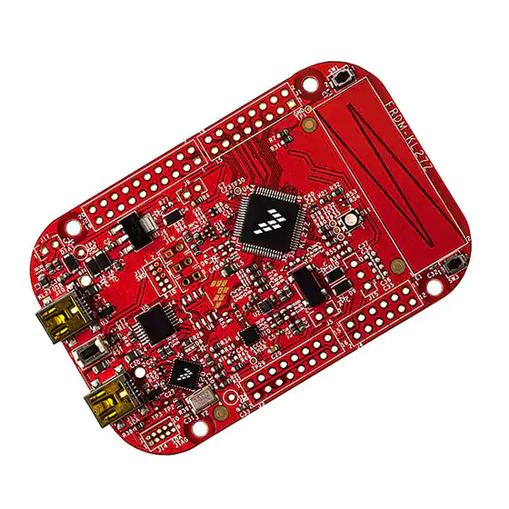
The Freescale KL27Z Freedom board (FRDM-KL27Z) is a
simple, yet sophisticated design featuring a Kinetis L series
microcontroller KL27Z, a 3.3V microcontroller built on the
ARM® Cortex®-M0+ core.
The Kinetis L series is the most scalable portfolio of
low-power, robust, mixed signal 32-bit ARM Cortex-M0+
MCUs running up to 48 MHz in the industry. It supports
power supply voltage range from 1.71V to 3.6V, ambient
operating temperature ranges from -40°C to 105°C and
includes up to 64 KB flash.
The FRDM-KL27Z includes the Freescale open standard
embedded serial and debug adapter known as OpenSDA.
This circuit offers the user several options for serial
communications, flash programming and run-control
debugging.
© 2015 Freescale Semiconductor, Inc. All rights reserved.
Document Number: FRDMKL27ZUG
Contents
1. Introduction . . . . . . . . . . . . . . . . . . . . . . . . . . . . . . . . . 1
2. Reference documents . . . . . . . . . . . . . . . . . . . . . . . . . . 2
3. Getting started . . . . . . . . . . . . . . . . . . . . . . . . . . . . . . . 2
4. FRDM-KL27Z hardware overview . . . . . . . . . . . . . . . 2
5. FRDM-KL27Z hardware description . . . . . . . . . . . . . 4
5.1. Power supply . . . . . . . . . . . . . . . . . . . . . . . . . . . . . . . . 4
5.2. Serial and debug adapter (OpenSDA) . . . . . . . . . . . . . 6
5.3. Debugging interface . . . . . . . . . . . . . . . . . . . . . . . . . . 7
5.4. Virtual serial port . . . . . . . . . . . . . . . . . . . . . . . . . . . . . 7
5.5. Clock source . . . . . . . . . . . . . . . . . . . . . . . . . . . . . . . . 7
5.6. Serial port . . . . . . . . . . . . . . . . . . . . . . . . . . . . . . . . . . 8
5.7. Reset . . . . . . . . . . . . . . . . . . . . . . . . . . . . . . . . . . . . . . 8
5.8. Debug . . . . . . . . . . . . . . . . . . . . . . . . . . . . . . . . . . . . . 8
5.9. Capacitive touch slider . . . . . . . . . . . . . . . . . . . . . . . . 8
5.10. 6-axis accelerometer and magnetometer . . . . . . . . . . . 9
5.11. RGB LED . . . . . . . . . . . . . . . . . . . . . . . . . . . . . . . . . 10
5.12. Input/output headers . . . . . . . . . . . . . . . . . . . . . . . . . 11
5.13. Arduino compatibility . . . . . . . . . . . . . . . . . . . . . . . . 11
6.2. Programming the ULPBench device software . . . . . 12
6.3. Hardware configuration . . . . . . . . . . . . . . . . . . . . . . . 12
6.4. EnergyMonitor connections . . . . . . . . . . . . . . . . . . . 13
7. Revision history . . . . . . . . . . . . . . . . . . . . . . . . . . . . . 13
Rev. 0, 02/2015
Advertisement
Table of Contents

Related Manuals for Freescale Semiconductor FRDM-KL27Z


Summary of Contents for Freescale Semiconductor FRDM-KL27Z
-
Page 1: Table Of Contents
3. Getting started ....... 2 and development tool ideal for rapid prototyping of 4. FRDM-KL27Z hardware overview ....2 microcontroller-based applications. The hardware design is 5. -
Page 2: Reference Documents
Arduino Uno: A guide to Arduino Uno revision Getting started Refer to the FRDM-KL27Z Quick Start Package for step-by-step instructions for getting started with the freedom board. See the “Jump Start Your Design” section at freescale.com/FRDM-KL27Z for the Quick Start Package and software lab guides. - Page 3 FRDM-KL27Z hardware overview Figure 1. FRDM-KL27Z block diagram The FRDM-KL27Z features two microcontrollers (MCUs): the target MCU and a serial and debug adapter (OpenSDA) MCU. The target MCU is a Kinetis series KL27 family device, the KL27Z64VLH4. The OpenSDA MCU is a Kinetis K series K20 family device, the K20DX128VFM5.
-
Page 4: Frdm-Kl27Z Hardware Description
FRDM-KL27Z hardware description Power supply The FRDM-KL27Z offers a design with multiple power supply options. It can be powered from the USB connector, battery on the board, the VIN pin on the I/O header, or an off-board 1.71-3.6V supply from the 3.3V pin on the I/O header. - Page 5 FRDM-KL27Z hardware description Figure 2. FRDM-KL27Z power supply Table 1 provides the operational details and requirements for the power supplies. Table 1. Tower supply requirements OpenSDA Regulated Supply Source Valid Range Operational? On-board? OpenSDA USB (J13) Mini USB(J10) P5V0-9V0_VIN Pin on I/O header 4.3-9V...
-
Page 6: Serial And Debug Adapter (Opensda)
Regulated 3.3V supply. Sources power to the P3V3 supply rail through an optional back drive protection Schottky diode. P3V3 Main supply rail for the FRDM-KL27Z. Can be sourced from P3V3_VREG. P3V3_KL27Z KL27Z MCU power supply. Header J17 provides a convenient means for KL27Z energy consumption measurements. -
Page 7: Debugging Interface
The Kinetis KL27 microcontrollers feature an on-chip oscillator compatible with input crystal: 32 to 40 KHz or 3 to 32 MHz. The KL27Z on the FRDM-KL27Z is clocked from the internal clock LIRC (2 MHz/8 MHz) or HIRC (48 MHz), and on-board 32768 Hz crystal for the RTC clock source. -
Page 8: Serial Port
The sole debug interface on all Kinetis L series devices is a Serial Wire Debug (SWD) port. The primary controller of this interface on the FRDM-KL27Z is the onboard OpenSDA circuit. However, a 2x5-pin (0.05”) Cortex Debug connector, J11, provides access to the SWD signals for the KL27Z MCU. -
Page 9: 6-Axis Accelerometer And Magnetometer
FRDM-KL27Z hardware description Figure 5. Touch slider connection 5.10 6-axis accelerometer and magnetometer A Freescale MMA8451Q low-power, three-axis accelerometer is interfaced through an I C bus and two GPIO signals as shown in Table 4. By default, the I C address is 0x1D (SA0 pulled high). -
Page 10: Rgb Led
FRDM-KL27Z hardware description This also designed to be compatible with 6-axis (FXOS8700CQ) combination of accelerometer and magnetometer sensor, if populating the U10 (FXOS8700CQ), and then keep U2 (MAG3310) DNP. Otherwise, populate U10 (MMA8451) and U2 (MAG3110). A Freescale MAG3110 low-power, three-axis magnetometer is interfaced through an I... -
Page 11: Input/Output Headers
5.13 Arduino compatibility The I/O headers on the FRDM-KL27Z are arranged to allow compatibility with peripheral boards (known as shields) that connect to Arduino and Arduino-compatible MCU boards. The pins on the headers share the same mechanical spacing and placement as the I/O headers on the Arduino Uno Revision 3 board design. -
Page 12: Using The Frdm-Kl27Z With Eembc Ulpbench
EnergyMonitor hardware and software can be found at EEMBC.org. The FRDM-KL27Z board can easily be modified to support the EEMBC ULPBench benchmark and the connection of the EEMBC EnergyMonitor v1.0. -
Page 13: Energymonitor Connections
The EnergyMonitor Vcc line should be connected to J17 pin2 and the EnergyMonitor GND line should be connected to TP4. Revision history This table provides a revision history for this document. Table 7. Revision history Rev. Date Substantive change(s) number 02/2015 Initial public release. FRDMKL27Z User’s Guide, Rev. 0, 02/2015 Freescale Semiconductor, Inc. - Page 14 Semiconductor, Inc., Reg. U.S. Pat. & Tm. Off. All other product or service names are the property of their respective owners. ARM and ARM Cortex are the registered trademarks of ARM Limited (or its subsidiaries) in the EU and/or elsewhere. All rights reserved. © 2015 Freescale Semiconductor, Inc. Document Number: FRDMKL27ZUG Rev. 0 02/2015...
Need help?
Do you have a question about the FRDM-KL27Z and is the answer not in the manual?
Questions and answers