
Related Manuals for EdilKamin MILLA H 15 Up


Summary of Contents for EdilKamin MILLA H 15 Up
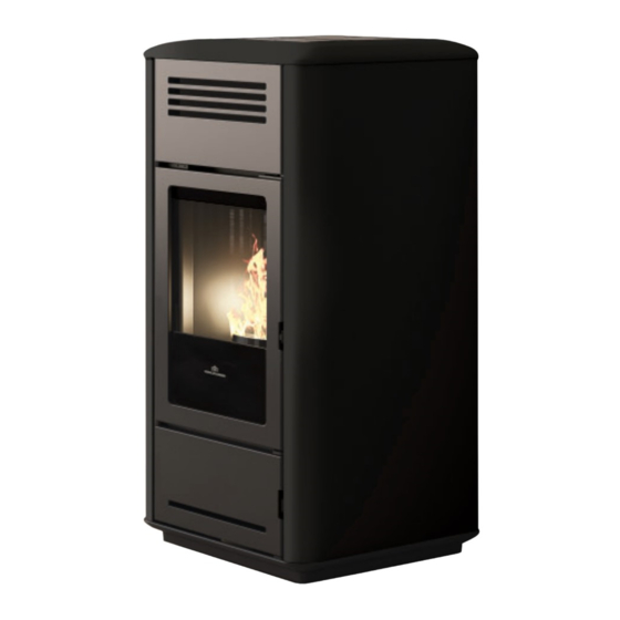
- Page 1 MILLA H 15 PELLET BOILER STOVE MILLA H 12 For all updates visit www.edilkamin.com Installation, use and maintenance page...
- Page 2 The original language of this manual is Italian The undersigned, EDILKAMIN S.p.A., with registered office in Via P . Moscati 8 - 20154 Milan (Italy) - Tax ID Code and VAT number 00192220192 Hereby declares, under its sole responsibility, that: the pellet stoves mentioned below comply with Regulation (EU) No.
-
Page 3: Meaning Of Symbols
• the purchase receipt given to you by the retailer; www.edilkamin.com • the declaration of conformity (or the documents required in the country of installation) issued to you by Readers of this manual the installer. - Page 4 • use of fuel other than wood warranties, refer to the pellets. DO NOT BURN warranty certificate inside WASTE MATTER, PLASTIC the product: specifically, OTHER MATERIALS neither Edilkamin nor the THAN WOOD PELLETS retailer are liable for damage COMBUSTION resulting from incorrect CHAMBER.
- Page 5 SAFETY INFORMATION • cleaning the smoke duct • use of the product as a with cleaning products. DO support ladder. NOT CLEAN THE PRODUCT NOT CLIMB ONTO THE WITH FLAMMABLE PRODUCT OR USE IT AS A PRODUCTS. Risk of fire or SUPPORT.
- Page 6 DIMENSIONS MILLA H 12 - MILLA H 15 (cm) 16,6 14,4 Ø 8 cm uscita fumi Ø 4 cm combustion air loading G 1/2” M return G 3/4” M delivery G 3/4” M MILLA H 12 MILLA H 15 (cm) USER/INSTALLER...
-
Page 7: Technical Data
TECHNICAL DATA TECHNICAL DATA as per EN 14785 MILLA H 12 Nominal power Reduced power Available power 12,4 Heat output to water 10,2 Efficiency 93,0 93,2 CO emissions at 13% O 0,004 0,009 Smoke temperature °C Fuel consumption * kg/h Tank capacity Recommended draught Autonomy... - Page 8 ECODESIGN TECHNICAL DATA TECHNICAL DOCUMENTATION FOR LOCAL SPACE HEATERS ACCORDING TO COMMISSION REGULATION (EU) 2015/1185 AND 2015/1186 Manufacturer Edilkamin S.p.A. Trademak Edilkamin Model Identifier Milla H 12 Description Mechanically space heater with boiler fired by wood pellets Indirect heating functionality...
- Page 9 TECHNICAL DATA TECHNICAL DATA as per EN 14785 MILLA H 15 Nominal power Reduced power Available power 15,3 Heat output to water Efficiency 92,1 93,2 CO emissions at 13% O 0,004 0,009 Smoke temperature °C Fuel consumption kg/h Tank capacity Recommended draught Autonomy Water content...
- Page 10 ECODESIGN TECHNICAL DATA TECHNICAL DOCUMENTATION FOR LOCAL SPACE HEATERS ACCORDING TO COMMISSION REGULATION (EU) 2015/1185 AND 2015/1186 Manufacturer Edilkamin S.p.A. Trademak Edilkamin Model Identifier Milla H 15 Description Mechanically space heater with boiler fired by wood pellets Indirect heating functionality...
-
Page 11: Preparation And Unpacking
UNPACKING PREPARATION AND UNPACKING The packaging materials are neither toxic nor noxious The packaging materials are neither toxic nor noxious and do not require special disposal. and do not require special disposal. The user is responsible for storing, disposing of and The user is responsible for storing, disposing of and recycling them in a regulatory fashion. - Page 12 UNPACKING Package materials such as plastic andfilms my be dangerous for children. Suffocation hazard. Keep packages away from children. DO NOT TRY TO REMOVE THE PRODUCT FROM THE PALLET WITHOUT HAVING OPENED THE COMBUSTION CHAMBER DOOR AND UNDONE THE SCREWS WHICH FIX IT TO THE PALLET TO REMOVE THE STOVE FROM THE PALLET Loosen the screws that secure the product to the pallet.
-
Page 13: Water Circuit Installation
(for example, in Italy, the reference is the Circular from ISPESL, now INAIL, of April 2011). This separation is easily carried out using KIT A2 from Edilkamin. • The presence of a puffer (inertial storage tank) is recommended but not mandatory. Its presence... - Page 14 WATER CIRCUIT INSTALLATION The pellet boiler stove is equipped with: - Hydraulic kit with closed expansion tank, - circulator pump - pressure relief valve. PIPE KIT Measurements in mm INSTALLER...
- Page 15 WATER CIRCUIT INSTALLATION PUMP SPECIFICATIONS The pump has no adjustment devices. Adjustments are made via the micro processor on the boiler stove: “begin” at the lowest speed and make adjustments based on the progression of the water temperature. Below is the descriptions for the LED signals. LEDS MEANING CAUSE...
-
Page 16: Installation
INSTALLATION TERMINAL BOARD One terminal board (10 poles) is low voltage and the other (6 poles) is high voltage. You can find some connection examples below. Poles are identified with a number on the product as described below Low voltage terminal board N°... -
Page 17: Adjustable Feet
• The appliance may not be installed in a bedroom, Contact the authorised Edilkamin Technical Assistance bathroom or in the same room as other equipment Centre. which draws air for combustion from the room itself, or in any area with an explosive atmosphere. - Page 18 INSTALLATION FLUE SYSTEM(SMOKE DUCT, FLUE AND FLUE SYSTEM(SMOKE DUCT, FLUE AND THE SMOKE DUCT THE SMOKE DUCT CHIMNEY POT) CHIMNEY POT) Further to the general prescriptions for the smoke duct Further to the general prescriptions for the smoke duct This chapter has been drawn up pursuant to European and flue, the smoke duct: and flue, the smoke duct: standards EN 13384, EN 1443, EN 1856 and EN 1457.
- Page 19 INSTALLATION THE FLUE: AIR INTAKE FOR COMBUSTION Further to the general prescriptions, the flue must In general, we suggest two ways to ensure a proper • only be used to discharge smoke flow of combustion air. Air must come from the outside* •...
- Page 20 The electrical system must be compliant; check the operation of the earth in particular. Edilkamin is not responsible for malfunctions resulting from an improperly earthed system. The power line must be of adequate section for the power of the appliance.
- Page 21 LINING Fig. 1 fig. 1 - Put the side (A) in this position - Use the screws to fix it - repeat for the other side Then, put the top. INSTALLER...
- Page 22 INTRODUCTION ABOUT USE FIRST IGNITION (COMMISSIONING) LOADING THE PELLETS INTO THE TANK. PHASES To access the tank, open the lid. • • Make sure you have read and understood this Make sure you have read and understood this manual. manual. When the boiler stove is hot, DO NOT •...
-
Page 23: Operation
USER INSTRUCTIONS OPERATION The product also has the following supplementary Mode Settable parameters functions. AUTOMATIC • desired room temperature • ventilation level * Function Modes in which What it does CRONO • desired room temperature, it can be acti- selected per day of the week vated •... -
Page 24: Introduction To Use
INTRODUCTION TO USE INTERFACE The product can be managed alternatively as follows STANDARD • DISPLAY: useful for all functions, located on By purchasing the Edilkamin optional elements: the product • VOICE CONTROL SYSTEMS: Alexa or Google Home • The Mind APP... - Page 25 OPTIONAL THERMOSTATS/PROBES CONNECTIONS OPTIONAL ELECTRICAL CONNECTIONS NOTE: The connections must be made by qualified A terminal board is present on the product (accessible personnel, with the electricity disconnected. by removing the covering, with electricity off and only by qualified technicians). More info for installers on the site.
- Page 26 INTRODUCTION TO USE The displays follow the functions at the same time and are described in the following paragraphs: 15:40 14.9 ° 1.2 bar - BUTTONS The display has 8 buttons: ON/OFF: to go from the OFF status to the ON status. In the Menus, to confirm and return to the main screen. +/-: to increase/decrease the set values or scroll the menu items M: to access the Menu or to exit the Menu items without saving OK: to confirm an operation (2 seconds) or to access a menu item...
- Page 27 USER INSTRUCTIONS From the display it is possible to: Switching on and off takes a few minutes, • Switch from OFF to ON status, during which the flame must appear or keeping the ON/OFF button pressed for a go out. Let it happen without intervening. long time During ignition, the display shows the word •...
-
Page 28: Fan Adjustment
USER INSTRUCTIONS - FAN ADJUSTMENT The setting can be made with the stove turned OFF or ON. If the backlight is switched off, it can be activated by pressing any button. Then by pressing button SET flashes and instead of environment Set, the indication of the number of fan in modification (F1) appears. -
Page 29: Alarm Status
USER INSTRUCTIONS POSSIBLE STATUSES of the product: - OFF STATUS The product is “deactivated” and does not produce heat, following manual shutdown with ON/OFF of the radio control or with intervention from an external contact (crono, telephone dialler). From the OFF screen, the ON screen can be accessed by pressing the ON/OFF button for 3 seconds. - ON STATUS Situation in which the product is “active”... - Page 30 USER INSTRUCTIONS - MENU It can be accessed by pressing the button and the first Menu item will appear. You can scroll the menu items with the buttons, and enter the item with the button The Menu items are as follows STAND-BY PELLET LOAD CRONO...
- Page 31 USER INSTRUCTIONS - STAND-BY With the Stand-by function active, when the desired temperature is reached, the product switches off and switches on again when the room temperature drops below the desired one. When the Stand-by function is not active, the product sets itself to minimum power when the temperature set-point is reached.
-
Page 32: Pellet Loading
USER INSTRUCTIONS - PELLET LOADING Allows for loading the pellets once the screw feeder has emptied completely. Useful for the technician during the initial start-up. Available only in the OFF status. Any attempt to activate the function in other statuses will not be allowed. To access the function from the main menu (as indicated in the Menu paragraph above), press the button You can scroll the menu items with the... - Page 33 USER INSTRUCTIONS - CRONO SETTING To access the function from the main menu (as indicated in the Menu paragraph above), press the button You can scroll the menu items with the buttons, and enter the item with the button 15:36 14.9 °...
- Page 34 USER INSTRUCTIONS The day of the week is selected by scrolling with buttons (at the same time the programming of that day is displayed) and confirmed with button day of the week 00:00 15:36 e.g. = MON = Monday 14.9 °...
- Page 35 USER INSTRUCTIONS SETTING TEMPERATURE FOR CRONO T1 – T2 TEMP. CRONO To access the function from the main menu (as indicated in the Menu paragraph above), press the button You can scroll the menu items with the buttons, and enter the item with the button After entering the T1-T2 function, the display will show the name of the function on the first line of the status bar and the current value of T1 on the second line.
-
Page 36: Date And Time
USER INSTRUCTIONS - DATE AND TIME Can be used to set the current date and time. To access the function from the main menu (as indicated in the Menu paragraph above), press the button You can scroll the menu items with the buttons, and enter the item with the button 15:36... -
Page 37: Language Setting
USER INSTRUCTIONS - LANGUAGE SETTING Selects the language. To access the function from the main menu (as indicated in the Menu paragraph above), press the button You can scroll the menu items with the buttons, and enter the item with the button When entering the Language Menu item, the name in the status bar on the first line of the function and on the second the current value is displayed (ITALIAN) -
Page 38: For The Installer
FOR INSTALLER INSTRUCTIONS FOR USE: MENU It can be accessed by pressing the button and the first Menu item will appear. You can scroll the menu items with the buttons, and enter the item with the button The Menu items are as follows STAND-BY: described in the user manual NOTE PELLET LOAD: described in the user manual... - Page 39 USER INSTRUCTIONS - DISPLAY Allows for choosing the level of brightness of the display. - INFO These readings should only be done when requested by the technician. The technician understands the diagnostic meaning of the messages and values, and may ask you to read them to him/her if you experience problems.
- Page 40 USER INSTRUCTIONS - SOFTWARE Indicates: • the firmware version of the electronic board (basic board) • the firmware version of the control panel • the database (associated by the Technical Assistance Centres with the products) To be read only under the guidance of the Technical Assistance Centre 15:36 °...
- Page 41 USER INSTRUCTIONS - INFO They provide instant situation values 15:36 ° 14.9 INFO 15:36 ° 14.9 FLUE TEMPERATURE 88.2°C Below is a description of the items Flue temperature indicates the value of the temperature read inside the product. To be read only under the guidance of the Technical Assistance Centre Auger motor: indicates the speed set and read.
- Page 42 USER INSTRUCTIONS - ALARMS These readings should only be done when requested by the technician. The alarms are arranged from the most recent to the oldest. 15:36 ° 14.9 ALARMS 15:36 ° 14.9 ALARMS A4 28/12/2020 The meaning of the abbreviations is given in the user manual USER...
- Page 43 USER INSTRUCTIONS - PELLET FALL Allows to set the gearmotor in continuous cycle or in steps. To be carried out only under the guidance of a technician. 15:36 ° 14.9 PELLET FALL 15:36 ° 14.9 PELLET FALL CONTINUES - PELLET SENSOR Allows to set the pellet level sensor ON or OFF.
- Page 44 USER INSTRUCTIONS IN ORDER OF SCROLLING IT IS FOUND AFTER THE TECHNICAL MENU - “SET TEMPERATURE” o the display (Setting the water temperatures) Allows the setting of the boiler temperature and possibly the storage temperature. If the external probe is activated, it allows the setting of the climatic curve instead of the boiler temperature.
-
Page 45: Technician Menu
INSTRUCTIONS FOR USE: TECHNICIAN MENU - TECHNICIAN MENU (for TECHNICIANS ONLY) Accessible only by a technician in possession of the correct password (1111) Once the password has been entered, it must be confirmed with a button - Flame type NOTES - Pellet type inappropriate changes can cause the product to seize up... - Page 46 INSTRUCTIONS FOR USE: TECHNICIAN MENU - PELLET TYPE In correct installation conditions, with the Service Centre parameters appropriately adjusted, with quality pellets, the pellet load is adjusted MEDIUM HIGH 15:36 ° 14.9 PELLET TYPE Enter the Pellet Type (%) setting with button and modify the value with buttons Pressing the button automatically takes you to the first level.
- Page 47 INSTRUCTIONS FOR USE: TECHNICIAN MENU - CONFIGURATION Scroll through the Technician Menu items with buttons to the “CONFIGURATION” item It is possible to enter the “CONFIGURATION” setting with button and modify the value with buttons Pressing the button automatically takes you to the first level. 15:36 °...
- Page 48 FOR THE INSTALLER: HYDRAULIC INSTALLATION To manage the various types of systems, connect the probes to the terminal board, as needed. TERMINAL BOARD MAIN OUTLINE 15-16 CYLINDER PROBE (Optional NTC 10K ) or THERMOSTAT (Optional) 13-14 DOMOTIC CONTACT (Input) 11-12 ROOM PROBE (Supplied) or ROOM THERMOSTAT (Optional) 9-10 BUFFER PROBE (Optional NTC 10K) - BUFFER THERMOSTAT (Optional)
-
Page 49: Daily Maintenance
MAINTENANCE DAILY MAINTENANCE These jobs should be done with the product off, cold and preferably disconnected from the mains. A suitable vacuum cleaner is required. Disconnect the product from the Make sure that the grate is power supply. properly placed in its Failure service product... - Page 50 MAINTENANCE Disconnect the product from the power supply. Failure to service the product properly will prevent it from working properly. Any problems due to failure in servicing the stove will void the warranty. DAILY MAINTENANCE 1. Pull the cleaning brush placed under the pellet load lid with the cold hand 2.
-
Page 51: Weekly Maintenance
MAINTENANCE WEEKLY MAINTENANCE When the product is off and cold, after having activated the cleaning brush as in routine maintenance, you should vacuum the inspection plate under the combustion chamber (*) To access: • Open the door using the cold handle (removable handle) •... -
Page 52: Seasonal Maintenance
- If any spare parts are required, contact your dealer You should clean the chimney system at least once a or technician. - Have any repairs carried out only by Edilkamin year (check local regulations for details). technical assistance centres/authorised dealers. -
Page 53: Troubleshooting
TROUBLESHOOTING If problems occur, the product shuts itself off automatically. The display will show the reason (see below). 15:36 14.9 ° BURNING POT DIRTY MESSAGE PROBLEM SOLUTION • Check that the combustion chamber door is closed A01 burning pot displays when the combustion •... - Page 54 TROUBLESHOOTING MESSAGE PROBLEM SOLUTION • Check the type of pellet (contact the technician if in Shutdown due to exceeding doubt) maximum smoke temperature. • contact the technician Switching OFF due to excessive • see HO7 overheating of the product Shutdown due to gearmotor •...
- Page 55 If the water in the product reaches a temperature of 85°C, the product shuts down without switching to alarm mode. The text STBY appears on the display next to the room temperature. The product is working, but it must be serviced by an authorised Edilkamin technician. MAINTENANCE (SIGNAL THAT DOES NOT CAUSE SHUTDOWN) A spanner symbol will appear on the display after 2,000 hours of operation The product is working, but it must be serviced by an authorised Edilkamin technician.
- Page 56 The names of Edilkamin official, authorised technical assistance centres (TAC) and distributors are available ONLY a www.edilkamin.com *942417-GB* w w w . e d i l k a m i n . c o m cod. 942417-GB 09.22/B...
Need help?
Do you have a question about the MILLA H 15 Up and is the answer not in the manual?
Questions and answers