Table of Contents
Advertisement
Quick Links
Advertisement
Table of Contents

Subscribe to Our Youtube Channel
Related Manuals for Vinotemp WINE-MATE WM-4510D


Summary of Contents for Vinotemp WINE-MATE WM-4510D
- Page 1 Customizable Wine Cooling System WM-4510HZD WM-6510HZD WM-8510HZD Installation, Use & Care Manual Read and save these instructions...
- Page 2 Important Safety Information NOTES: • Do not plug in until 24 hours after delivery. • Do not use a ground fault interrupter (GFI). • Do not use an electrical extension cord. • A dedicated 20 AMP circuit is required for WM-4510HZD and 30 AMP is required for WM-6510HZD &...
-
Page 3: Table Of Contents
Table of Contents Cellar Construction.…………………….……………………..3 Features & Specifications.…………………….……………..4 Control Panel……………………………………..……..……7 Temperature & Humidity…………………………..…………8 Installation Instructions……………..………………………12 Care Guide…………………………………………………….24 Troubleshooting………….…………………………………..25 Electrical Diagrams………………..…………………….…28 Customer Support……………………………………………36 Warranty……………………………………………………….37 - 2 -... -
Page 4: Cellar Construction
Cellar Construction This is only a guide and shall be considered as minimum requirements. All interior walls and floors shall have a vapor barrier and a minimum of R13 insulation. All exterior walls and ceiling shall have a vapor barrier and a minimum of R19 insulation. -
Page 5: Features & Specifications
Features and Specifications Purpose of the cooling units • WM-4510~8510HZD cooling units are designed and used to provide a ° stable temperature between 50~65 F for a properly insulated and sized space. • The refrigerated space will maintain humidity within the range of 50~70% •... - Page 6 CELLAR DIMENSIONS (“) AIR FILTER DUCT ELECTRICAL WEIGHT MODEL NO SIZE FLOW WxW1xD (“, nominal) (“) RATING (lb) (cu ft) (cfm) xD1xD2xH 14.375x0.25x21.5 WM-4510HZD 1000 11.5x13.5x1 115V/60Hz/8A x1.25x1x20 17.125x0.25x28.375 WM-6510HZD 1500 13.5x14.5x1 115V/60Hz/14A x1.25x1x22.125 17.125x0.25x28.375 WM-8510HZD 2000 13.5x14.5x1 115V/60Hz/16A x1.25x1x22.125 NOTES: •...
- Page 7 NOTE: WM-4510HZD is 14.25” wide, WM-6510HZD & 8510HZD is 17” wide without the front cover. Fig. 1.2 Feature descriptions Fig. 1.3 Exterior wall grille - 6 -...
-
Page 8: Control Panel
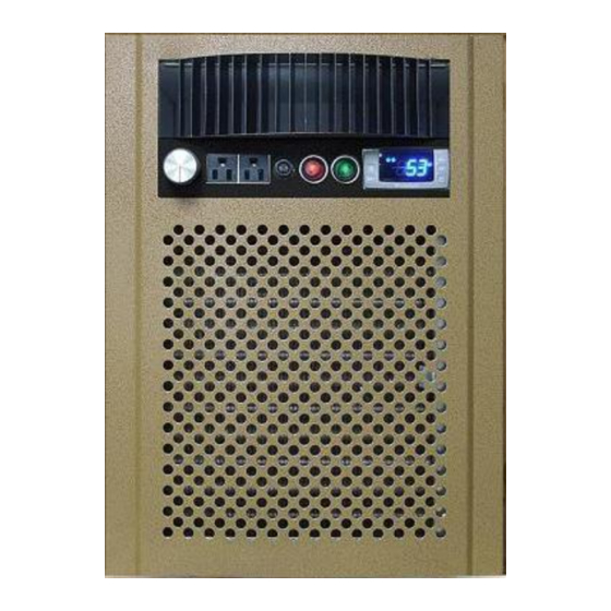
Control Panel Fig. 2.1 Control panel 1. Evaporator fan speed control Turn the knob clockwise to the lowest speed position for non-duct installations; turn counter-clockwise to achieve required air flow CFM for the duct installations. 2. Humidifier outlet Plug in your own independent humidifier in the extremely dry conditions. 3. -
Page 9: Temperature & Humidity
Temperature and Humidity 1. The controller Fig. 3.1 TEMPERATURE CONTROLLER 1) Keys SET: To display set-point; in programming mode it selects a parameter or confirms an operation. : To start a manual defrost. : To see the maximum stored temperature; in programming mode it browses the parameter codes or increases the displayed value. - Page 10 4) Alarm Signals The alarm codes are described as follows. MESSAGE CAUSE FUNCTION Temperature probe faulty Compressor switching to Con and CoF Probe temperature ALU higher than the High temperature alarm setting temperature; Outputs unchanged Probe temperature ALL lower than the Low temperature alarm setting temperature;...
- Page 11 6. Parameter Programming 1) Press and hold the SET + keys until the “°C” or “°F” LED starts flashing, then release the keys. 2) Press and hold again the SET + keys until the Pr2 label is displayed, then release the keys. The first parameter Hy will be displayed. 3) Press up/down keys to scroll to the required parameter within 10 sec.
- Page 12 • If the air probe is in a return duct, the evaporator fans shall be running all the time. Meanwhile due to the temperature differential the air probe calibration should be used in order to maintain the proper wine cellar temperature. 8.
-
Page 13: Installation Instructions
Installation Instructions NOTE: • Mounting brackets, screws, gaskets and other seal materials are not included. • Filter adapter, air filter, rear exhaust grille, duct hoods and insulated ducts are sold separately. 1. General Instructions Fig. 4.1 Cooling Unit Installation - 12 -... - Page 14 1) The cooling unit produces cooling supplied into the cellar, meanwhile it also generates heat that must be exhausted outside the cellar. So the cold-air supply and cellar-air return side must be separated from the hot-air exhaust and ambient-air intake side. Through-wall or through-duct installations can separate these two sides.
- Page 15 Fig. 4.2 Flush to the outside of wall with wall grille Fig. 4.3 Flush to the outside of wall with air filter & rear exhaust grille - 14 -...
- Page 16 Fig. 4.4 Top exhaust with air filter & rear exhaust cover Fig. 4.5 Flush to the racks or the inside of wall with air filter & rear exhaust grille NOTE: Insulate any cold surfaces of cooling unit for better performance if exposed to the outside.
- Page 17 3. Through-wall installation with hot-air exhaust and ambient-air intake ducts (Fig. 4.6 & 4.7) It is the installation when the cooling unit can not exhaust the hot air to an adjacent space. 1) The cooling unit shall be mounted near the ceiling with equal distance from each side of the cellar.
- Page 18 Fig. 4.6 Flush to the outside of wall with hot-air exhaust & ambient-air intake ducts Fig. 4.7 Flush to the outside of wall with hot-air exhaust duct & air filter 4. In-cellar installation with hot-air exhaust and ambient-air intake ducts (Fig.
- Page 19 Fig. 4.8 In-cellar with hot-air exhaust & ambient-air intake ducts Fig. 4.9 In-cellar with hot-air top exhaust duct to attic & ambient-air intake ducts - 18 -...
- Page 20 Fig. 4.10 Floor-mount with hot-air top exhaust duct to attic & ambient-air intake duct Fig. 4.11 Floor-mount with hot-air top exhaust duct to attic & air filter &rear exhaust cover 5. Through-wall installation with cold-air supply ducts (Fig 4.12) It is the installation when the cooling unit is located away from the wine rack. NOTE: - 19 -...
- Page 21 • The supply duct can be maximum 50 ft long. • The cooling unit can also be installed with other configurations shown above. Fig. 4.12 Flush to the outside of wall with cold-air supply duct & wall grille 6. Remote installation with cold-air supply and cellar-air return ducts only (Fig.
- Page 22 9) Turn the evaporator fan control knob counter-clockwise to achieve the required air flow CFM. Fig. 4.13 Cold-air supply and cellar-air return ducts only 7. Remote installation with cold-air supply, cellar-air return, hot-air exhaust and ambient-air intake ducts (Fig. 4.14 & 4.15) It is the installation when the cooling unit can not be installed inside the wine room and it can not exhaust the hot air to an adjacent space.
- Page 23 9) Turn on the high condenser fan switch. 10) Turn the evaporator fan control knob counter-clockwise to achieve the required air flow CFM. Fig. 4.14 Cold-air supply, cellar-air return, hot-air exhaust and ambient-air intake ducts - 22 -...
- Page 24 Fig. 4.15 Cold-air supply, cellar-air return and hot-air exhaust ducts - 23 -...
-
Page 25: Care Guide
Care Guide 1. Cleaning Condenser • Clean the condenser and air filter regularly. Condenser and filter may need to be cleaned at least every 6 months. • Condenser and air filter are located on the ambient air intake side of the cooling unit. -
Page 26: Troubleshooting
Troubleshooting This Troubleshooting Chart is not prepared to replace the training required for a professional refrigeration service person, not is it comprehensive Complaint Possible Causes Response a. Power cord not plugged a. Check power cord 1. Unit not b. No power from supply b. - Page 27 high or not opening b. Cellar too large b. Check for excessive size cooling and c. Ambient temperature too high c. Check installation location running d. Exhaust restricted d. Leave minimum 3 feet clearance for continually the hot air exhaust side and leave minimum 1 foot clearance for the fresh air intake side e.
- Page 28 b. Low ambient temperature b. Move to another location c. Air probe fault c. Change a new one d. Temperature controller fault d. Change a new one a. Evaporator air flow restriction a. Check for fans and air flow 13.Evaporator b.
-
Page 29: Electrical Diagrams
Electrical Wiring Diagrams Fig. 7.1 WM-4510 ~ 8510HZD standard wiring diagram - 28 -... - Page 30 Fig. 7.2 WM-4510 ~ 8510HZD crankcase heater wiring diagram - 29 -...
- Page 31 Fig. 7.3 WM-4510 ~ 8510HZD alarm call wiring diagram - 30 -...
- Page 32 Fig. 7.4 WM-4510 ~ 8510HZD cellar heater wiring diagram - 31 -...
- Page 33 Fig. 7.5 WM-4510 ~ 8510HZD crankcase heater & alarm call wiring diagram - 32 -...
- Page 34 Fig. 7.6 WM-4510 ~ 8510HZD crankcase heater & cellar heater wiring diagram - 33 -...
- Page 35 Fig. 7.7 WM-4510 ~ 8510HZD alarm call & cellar heater wiring diagram - 34 -...
- Page 36 Fig. 7.8 WM-4510 ~ 8510HZD crankcase heater, alarm call & cellar heater wiring diagram - 35 -...
-
Page 37: Customer Support
Customer Support If you need further assistance, please contact us at: Vinotemp International 17631 South Susana Road Rancho Dominguez, CA 90221 Tel: (310) 886-3332 Fax: (310) 886-3310 Email: info@vinotemp.com - 36 -... -
Page 38: Warranty
BTU/H. While every effort has been made to provide accurate guidelines, VINOTEMP can not warranty its units to cool a particular enclosure. In case of failure, VINOTEMP cooling units must be repaired by the factory or its authorized agent. Repairs or modifications made by anyone else will void the warranty. - Page 39 VINOTEMP will, at its discretion, repair or replace the unit and return it free of charge to the original retail customer. If the unit is found to be in good working order, or beyond the initial twelve month period, it will be returned freight collect.
Need help?
Do you have a question about the WINE-MATE WM-4510D and is the answer not in the manual?
Questions and answers