
Subscribe to Our Youtube Channel
Related Manuals for Advanced Energy Thyro-S 1S H 1 Series

Summary of Contents for Advanced Energy Thyro-S 1S H 1 Series
- Page 1 THYRO-S THYRISTOR-SCHALTER Thyro-S 1S...H 1 Thyro-S 1S...H RL1 THYRISTOR-SWITCH Thyro-S 1S...H 1 Thyro-S 1S...H RL1 8000029341 DE/EN - V7 AUGUST 2015...
- Page 3 THYRO-S THYRISTOR-SCHALTER Thyro-S 1S...H 1 Thyro-S 1S...H RL1 THYRISTOR-SWITCH Thyro-S 1S...H 1 Thyro-S 1S...H RL1 8000029341 DE/EN - V7 AUGUST 2015...
-
Page 4: Contact
Advanced Energy. © Copyright Advanced Energy Industries GmbH 2014. All rights reserved. FURTHER INFORMATION ON COPYRIGHT Thyro-S is an registered trademark of Advanced Energy Industies GmbH. Windows and Windows NT are registered trademarks of the Microsoft Corporation. -
Page 5: Safety Instructions
SAFETY INSTRUCTIONS The following safety and operating instructions must be carefully read before assembly, installation and commissioning. OBLIGATION TO GIVE INSTRUCTIONS The following safety and operating instructions must be carefully read before initial assembly, installation and commissioning of Thyro-S by those persons working with or on Thyro-S. - Page 6 RESIDUAL HAZARDS OF THE PRODUCT • Even in case of proper use, should a fault occur, it is possible that control of currents, voltages and power is no longer performed in the load circuit by the Thyristor switch. In case of destruction of the power components (e.g break-down or high resistance), the following situations are possible: power interruption, half-wave operation, continuous power flow.
- Page 7 Danger of electric shocks. Even when the Thyristor switch is not trigge- red, the load circuit is not disconnected from the mains. ATTENTION Different components in the power section are screwed into place using exact torques. For safety reasons, power component repairs must be performed by Advanced Energy Industries GmbH.
-
Page 8: Table Of Contents
CONTENTS Contact Safety instructions Safety regulations Remarks on the present operating instructions and Thyro-S 1. Introduction 1.1 General 1.2 Specific characteristics Thyro-S 1.2.1 Additional for 1S…H RL1 1.3 Type designation 2. Functions 2.1 Operating modes 2.1.1 Digital set point value inputs 2.1.2 Switching behaviour 2.2 Indications 2.3 Monitoring... - Page 9 5. Interfaces 5.1 Bus module at the systems interface 5.2 PC-Interface RS232 at the system interface 5.2.1 Thyro-Tool Family 6. Mains load optimization 7. Connecting diagrams 8. Special remarks 8.1 Installation 8.2 Commissioning 8.3 Service 8.4 Checklist 9. Type overview 9.1 Typ 1S...H 1 9.2 Typ 1S...H RL1 10.
- Page 10 LIST OF ILLUSTRATIONS AND TABLES Fig. 1 Block diagram 1S...H1 Fig. 2 Terminal plan 1S...H1 Fig. 3 Operation 1S...H 1 Fig. 4 Block diagram 1S...H RL1 Fig. 5 Terminal plan 1S...H RL1 Fig. 6 Operation Thyro 1S...H RL 1 Fig. 7 User surface Thyro-Tool Family Fig.
-
Page 11: Safety Regulations
SAFETY REGULATIONS IMPORTANT INSTRUCTIONS AND EXPLANATIONS The skilled personnel assembling and disassembling the devices, commissioning them and maintaining them must know and observe these safety regulations. CAUTION This instruction indicates work and operating procedures to be observed exactly to exclude hazards to persons. ATTENTION This instruction refers to work and operating procedures to be observed exactly to avoid damage or destruction of Thyro-S or parts thereof. - Page 12 (e.g. overload) may occur. Any unauthorized reconstruction and modification of Thyro-S, use of spare and exchange parts not approved by Advanced Energy as well as any other use of Thyro-S is not permitted. The person responsible for the system must ensure that...
- Page 13 Type name Production number Complaint Ambient conditions Operating mode Duration of use GUIDELINES The CE mark on the device confirms adherence to the general EC guidelines for 2006/95 EEC – low voltage and for 2004/108 EEC electromagnetic compatibility if the instructions on installation and commissioning described in the operating instructions are observed.
-
Page 14: Remarks On The Present Operating Instructions And Thyro-S
Any complaints on goods delivered are to be submitted, together with the delivery note, within eight days of receipt. All guarantees made by Advanced Energy and its dealers will be cancelled without prior notice if other than original Advanced Energy spare parts or spare parts purchased by Advanced Energy are used for maintenance and repair. -
Page 15: Introduction
1. INTRODUCTION Thyro-S meets the demands for simple assembly, speedy commissioning and safer operation. For transport, assembly, installation, commissioning, operation and decommissioning, it is essential that the safety instructions included in these operating instructions are observed and made available to all persons handling this product. -
Page 16: Type Designation
Options: • Bus connection via bus adapter Coupling to different bus systems, e.g. Profibus, Modbus RTU, CANopen and DeviceNet, other bus systems on request. • PC software Thyro-Tool Familiy, visual and operational software 1.2.1 EXTENSION USING 1S...H RL1 • With additional 24 V control voltage supply also applicable for mains voltages >... -
Page 17: Functions
2. FUNCTIONS 2.1 OPERATING MODES FULL WAVE SWITCH Depending on the digital set point signal the mains voltage is switched. In the operating mode 1:1 almost no harmonics are created in the mains frequency. Whole multiples of the mains periods are always switched. -
Page 18: Indications
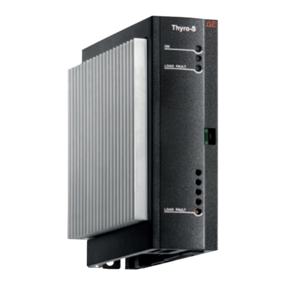
signal is interrupted up to 1.25 ms before the crossover of the full wave. With a pulse trigger the pulse duration must be min. 1 ms. 2.2 INDICATIONS The LEDs on the front signal the following states: • ON GREEN operating indication, power supply controller device Blinking indications are described in table 2. -
Page 19: Additional Indications Using Type S
2.4 ADDITIONAL INDICATIONS USING TYPE S...H RL1 The LEDs on the front indicate the following situations: • Diagnosis GREEN additonal error diagnosis • LOAD FAULT error present Flashing LED indications are described in table 2. Whether the semi- conductor fuse is responding can be indicated by the error indication relay K1 (undercurrent detection). -
Page 20: Load Monitoring (Undercurrent Monitoring)
2.5.2 LOAD MONITORING (UNDERCURRENT MONITORING) Thyro-S ... H RL1 is suitable for monitoring loads resulting from one or several resistances in parallel or parallel series connection. Thyro-S detects an increase in the load resistance. The load monitoring operates as undercurrent monitoring on absolute values and is suitable for use in the nominal operating mode 1:1, and with limitations in the operating modes 1:2. - Page 21 RECOM- RESISTANCE MENDED NO. OF INCREASE IN PARALLEL SETTING POTI CASE FOR POTI LOAD RESIS- REVOLU- LOAD NOM OF FAULT TANCES E.G. R205 TIONS CA. TYPE/CONTROLLER NUMBER 100% 50.0% 40.0% Infinite 30.0% 20.0% 10.0% 100% 75.0% 60.0% 100,0% 45.0% 30.0% 15.0% 100% 83.3%...
-
Page 22: Operation
3. OPERATION 3.1 CONFIGURATION SWITCH S1 A 4-pole DIP switch is situated at the front behind the hood. The indi- vidual switches are marked from 1-4 starting from the bottom and must be set before operation. They are only read in once when switched on (mains recovery). -
Page 23: Thyro-Tool Family
3.2 THYRO-TOOL FAMILY Thyro-S 1S is suitable for operation with the visual and operational soft- ware Thyro-Tool Family. No special setting is necessary here. Further information is contained in chapter 5. 3.3 DIAGNOSIS / STATUS INDICATION Faults can occur in the load circuit and in the controller itself or from the mains. - Page 24 TAB. 2 LED SIGNALS THYRO-S...
-
Page 25: External Connections
4. EXTERNAL CONNECTIONS To connect the control signals use twisted or screened control lines. If the controller is being used in UL conditions then only 60°C or 75°C copper wires are to be used for the power connections in accordance with the instructions in the technical data. -
Page 26: Digital Set Point Input
The 24 V connection lines are to be fused in accordance with the appli- cable regulations. A soldered in fuse protects the device in case of internal short-circuits. 4.4 DIGITAL SET POINT INPUT The digital set point input X22.1 works with a logic signal. It can, for example, be gated by 24 V DC. - Page 27 4.5 BLOCK DIAGRAM 1S...H 1 only for HF modules FIG. 1 BLOCK DIAGRAM...
- Page 28 4.6 CONNECTIONS AND TERMINAL STRIPS 1S...H 1 This chapter describes all existing terminal strips and plug connections. System interface Earth RM 3.5 RxD / connection to bus module TxD / connection to bus module Bus module recognition Earth Pos. power supply unstabilised (usable as source for terminal 1) Control signal (On >...
-
Page 29: Block Diagram 1S
4.7 BLOCK DIAGRAM 1S ... H RL1 In the block diagram the functions of type H RL1 are shown. The central control element is a -controller. FIG. 4 BLOCK DIAGRAM... -
Page 30: Connections And Terminal Strips
4.8 CONNECTIONS AND TERMINAL STRIPS This chapter describes all existing terminal strips and plug connections. Indication relay K1 N/C contact, in case of error closed RM 5.08 N/O contact, in case of error open (no-load current principle) Root, common connection System interface Control earth (5 / 3.3 V) RM 3.5... - Page 31 GREEN GREEN Diagnosis LOAD FAULT Without function S1-4 Thyro-Tool Mode chapter 3.1 S1-3 Operating mode chapter 3.1 S1-2 Operating mode S1-1 R205 Load monitoring LOAD FAULT chapter 2.3 FIG. 6 OPERATION THYRO 1S...H RL1...
-
Page 32: Interfaces
5. INTERFACES The Thyristor Switch of type range Thyro-S...1 are all equipped with a system interface at terminal strip X22. Either a bus module or a PC interface with a PC connection can be operated from this. 5.1 BUS MODULE AT THE SYSTEM INTERFACE The optional bus module enables the Thyro-S range Power Controller to be connected to a field bus. -
Page 33: Thyro-Tool Family
5.2.1 THYRO-TOOL FAMILY FIG. 7 USER SURFACE THYRO-TOOL FAMILY Thyristor Switch of the Thyro-S range can be operated and set effort- lessly with the aid of the PC software Thyro-Tool Family. Necessary for working with Thyro-Tool Family is that the connection between PC and Power Controller is present (see 5.2). -
Page 34: Mains Load Optimization
6. MAINS LOAD OPTIMIZATION Thyro-S is not suitable for mains load optimization in multiple controller applications. If mains load optimization is necessary, Thyristor controllers of type Thyro-A, Thyro-AX or Thyro-P must be used. 7. CONNECTING DIAGRAMS Thyro-S can be employed in single phase switch and in three phase switches which can be transposed to single phase switches, e.g. - Page 35 FIG. 8 CONECTION DIAGRAM THYRO-S 1S...H 1...
- Page 36 FIG. 9 CONNECTING DIAGRAM 2X THYRO-S 1S...H 1...
- Page 37 FIG. 10 CONNECTING DIAGRAM THYRO-S 1S...H RL1...
- Page 38 FIG. 11 CONNECTING DIAGRAM 2X THYRO-S 1S...H RL1...
-
Page 39: Special Remarks
8. SPECIAL REMARKS 8.1 INSTALLATION Thyro-S requires a vertical fitting position. With cabinet mounting suffi- cient ventilation of the cabinet must be ensured. The distance between the Power Controller and the cabinet ceiling or other mountings should be at least 150 mm. The distance below the Power Controller should be at least 100 mm. -
Page 40: Checklist
Should nevertheless faults or problems occur, our technical contacts are at your service. 8.4 CHECKLIST • LED ON lights up green -> mains voltage or supply voltage is available • LED ON not lights up green · Check fusing of the power unit (built in semi-conductor fuse F1). If the fuse is defective check load and wiring to load. -
Page 41: Type Overview
9. TYPE OVERVIEW 9.1 TYPE 1S...H 1 Thyristor switches with incorporated semiconductor fuse and system bus interface. DIMENSIONS IN TYPE CAPACITY MM / KG [KW] 230 V 400 V 500 V DISSI- WEIGHT DIM. TYPE CURRENT FUSE DRAW PATION 22.5 HF 1 9.2 TYPE 1S...H RL1 Thyristor switches with incorporated semiconductor, system bus inter-... -
Page 42: Technical Data
10. TECHNICAL DATA Type voltage 230 Volt, 400 Volt, 500 Volt S..H1 – 57 % + 10 %; S..HRL1 230 Volt – 15 % + 10 %; > 99 V with additional 24 AC/DC elektronic power 400 Volt – 15 % + 10 %; >... - Page 43 Ambient temperature Max. surrounding air temperature 40 °C 45 °C natural air cooling (without fan) If the maximum ambient temperature is reduced then the maximum load cur- rent can be increased up to 110% of the nominal current. In which case the following applies: 1% more current requires a temperature reduction of 1 °C.
-
Page 44: Dimensional Drawings
11. DIMENSIONAL DRAWINGS THYRO-S 1S (16H, 30H) THYRO-S 1S (45H, 60H) -
Page 45: Dimensional Drawing Thyro-S 1S (100H)
THYRO-S 1S (100H) THYRO-S 1S (130H, 170H) -
Page 46: Dimensional Drawing Thyro-S 1S (280H)
THYRO-S 1S (280H) -
Page 47: Accessories And Options
12. ACCESSORIES AND OPTIONS Order no. 8.000.006.763 Support for 35 mm snap-on assembly 16 A and 30 A Order no. 8.000.010.791 Support for 35 mm snap-on assembly for 45 A and 60 A Order no. 2.000.000.380 PC Software Thyro-Tool Family Order no. -
Page 48: Approvals And Conformities
13. APPROVALS AND CONFORMITIES No product norm exists for Thyristor switches so that a useful norm structure can be built up based on the corresponding basic norms ensuring reliable application and comparison potential. CAUTION Thyristor switches are not devices for disconnection in the sense of EN 50110-1 and may therefore be operated only in connection with a suitable mains isolating device (e.g. - Page 49 IN DETAIL CONDITIONS FOR USEN Built-in unit (VDE 0160) EN 50 178 General requirements EN 60146-1 Design, vertical installation Operating conditions EN 60 146-1-1; K. 2.5 Operating location, industry sector CISPR 6 Temperature behaviour EN 60 146-1-1; K 2.2 Storage temperature -25 °C - +55 °C Transport temperature -25 °C - +70 °C...
- Page 53 1625 Sharp Point Drive Fort Collins, CO 80525 USA Specifications are subject to change without notice. 970.221.4670 Main © 2014 Advanced Energy Industries, Inc. All rights reserved. Advanced Energy and Thyro-S are ® 970.221.5583 Fax trademarks of Advanced Energy Industries, Inc.
Need help?
Do you have a question about the Thyro-S 1S H 1 Series and is the answer not in the manual?
Questions and answers