Mindray TEX10 Pro Manuals
Manuals and User Guides for Mindray TEX10 Pro. We have 3 Mindray TEX10 Pro manuals available for free PDF download: Service Manual, Operator's Manual
Mindray TEX10 Pro Service Manual (445 pages)
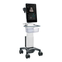
Diagnostic Ultrasound System
Brand: Mindray
|
Category: Diagnostic Equipment
|
Size: 10 MB
Table of Contents
-
Preface24
-
Introduction38
-
Intended Use38
-
PC Module47
-
GPU Module47
-
Probe Board48
-
AC-DC Board50
-
UI Unit56
-
ECG Module59
-
Probes62
-
Installation69
-
Unpacking74
-
Packing Box74
-
Software Setup100
-
Description128
-
Running Status128
-
Routine Check129
-
Check Process129
-
Check Items130
-
Function Check132
-
Check Process132
-
Check Items133
-
Performance Test142
-
Self-Tests166
-
User Self-Test172
-
Test Report173
-
Exporting Logs176
-
Viewing Logs177
-
Upgrade186
-
Upgrade Method186
-
Upgrade Method189
-
FRU Replacement192
-
System Structure192
-
Unpacking Tools192
-
Sketch193
-
Speaker (FRU)196
-
Main Unit204
-
Slide Assembly206
-
PC Module (FRU)211
-
GPU Module (FRU)214
-
SSD Card(FRU)220
-
Main Unit229
-
Hook Cover (Sy)233
-
Hook for Wire234
-
Base Cover254
-
Castor (FRU)259
-
Storage Box268
-
Battery (FRU)281
Advertisement

Mindray TEX10 Pro Operator's Manual (330 pages)
Diagnostic Ultrasound System
Brand: Mindray
|
Category: Diagnostic Equipment
|
Size: 8 MB
Table of Contents
-
Warranty4
-
Latex Alert23
-
Intended Use25
-
Power Supply26
-
Options28
-
I/O Module33
-
Indicators34
-
ECG Module36
-
Air Station37
-
Ivocal Plus44
-
Cine Review47
-
Auto Review48
-
Cine Saving50
-
Live Capture50
-
Live Capture51
-
Power ON/OFF58
-
Standby60
-
Setup67
-
Region67
-
General68
-
Image Preset70
-
Maintenance82
-
Ivision83
-
Security84
-
Egateway Preset101
-
Network Preset103
-
Route Settings104
-
X-Link104
-
Q-Path Preset105
-
Exam Preparation107
-
Activate an Exam109
-
Continue an Exam109
-
End an Exam109
-
B Mode111
-
Color Mode115
-
Power Mode118
-
M Mode120
-
PW/CW Mode122
-
Tdi125
-
Image Review130
-
Cine Review131
-
Smart B-Line131
-
Overview133
-
Smart VTI133
-
Smart IVC134
-
Contrast Imaging136
-
Image Parameters138
-
Image Saving139
-
Auto GA143
-
Auto DFR144
-
Smart Echovue144
-
Smart Nerve145
-
Smart FHR OB1146
-
Smart TTQA146
-
Bulleye152
-
Data Export152
-
Application152
-
Overview153
-
View Operation153
-
Insert154
-
Image Parameters155
-
Mass Measurement156
-
Smart 3D157
-
Overview157
-
Terms157
-
ROI and VOI158
-
Render Mode158
-
Mpr159
-
Note before Use160
-
Image Saving166
-
Ecg169
-
Respiratory Wave171
-
ECG Review171
-
Review Principle171
-
Measurement173
-
Annotations175
-
Body Mark177
-
Storage Media179
-
Thumbnails180
-
Report Storage181
-
Recycle bin183
-
Istorage184
-
Print184
-
Image Printing184
-
Report Printing185
-
V-Access186
-
Q-Path186
-
X-Link187
-
Dicom/Hl7189
-
DICOM Storage189
-
DICOM Print190
-
Worklist190
-
Mpps191
-
Query/Retrieve192
-
Media Storage192
-
Media Review193
-
Data Restore193
-
Probes195
-
Biopsy Guide213
-
Disposal250
-
Middle Line250
-
Espacial Navi250
-
Interface251
-
Preset253
-
Procedure254
-
Disposal256
-
DVR Recording257
-
Start Recording257
-
Sending Image257
-
Replay on PC258
-
Troubleshooting265
-
A Wireless LAN268
-
IP Configuration268
-
EAP Network268
-
Specifications268
-
Troubleshooting269
-
B Iscanhelper271
-
C Ivision273
-
Option of Demo273
-
Power Cord Plug279
-
The Power Plug279
-
Device Labeling280
-
MI/TI Display293
-
Acoustic Output294

Mindray TEX10 Pro Operator's Manual (370 pages)
Diagnostic Ultrasound System
Brand: Mindray
|
Category: Diagnostic Equipment
|
Size: 18 MB
Advertisement