Table of Contents
Advertisement
Quick Links
Advertisement
Table of Contents

Related Manuals for Analytik Jena CyBio Well vario OL3381-25-300


Summary of Contents for Analytik Jena CyBio Well vario OL3381-25-300
- Page 1 Operating Manual ® CyBio Well vario...
- Page 3 ........
- Page 5 EG Konformitätserklärung EC Declaration of Conformity Name und Anschrift des Herstellers: Name and address of the manufacturer: Analytik Jena AG Konrad-Zuse-Straße 1 D-07745 Jena Hiermit erklären wir, dass das nachstehend beschriebene Produkt Herewith we declare, that the product described below ®...
-
Page 9: Table Of Contents
Table of contents General Information ..........1 General User Manual Advice ... - Page 10 4.2.6 Tip Magazine (Pipetting Head) . . . . . . . . . . . . . . . . . . . . . . . . . . . . . . . . 31 4.2.7 Capillary Magazine (Capillary Head) . . . . . . . . . . . . . . . . . . . . . . . . . . . . 31 4.2.8 Terminals . . . . . . . . . . . . . . . . . . . . . . . . . . . . . . . . . . . . . . . . . . . . . . . . 32 4.2.9 Compressed Air Control Unit with vacuum suction . . . . . . . . . . . . . . . . 33 Tip Wash Station 1536 Set . . . . . . . . . . . . . . . . . . . . . . . . . . . . . . . . . . . . . 34 4.3.1 General Information. . . . . . . . . . . . . . . . . . . . . . . . . . . . . . . . . . . . . . . . 34 4.3.2 Overview . . . . . . . . . . . . . . . . . . . . . . . . . . . . . . . . . . . . . . . . . . . . . . . . 35 4.3.3 Safety Notes . . . . . . . . . . . . . . . . . . . . . . . . . . . . . . . . . . . . . . . . . . . . . 36 4.3.4 Components . . . . . . . . . . . . . . . . . . . . . . . . . . . . . . . . . . . . . . . . . . . . . 37 4.3.5 Operation . . . . . . . . . . . . . . . . . . . . . . . . . . . . . . . . . . . . . . . . . . . . . . . 40 Function . . . . . . . . . . . . . . . . . . . . . . . . . . . . . . . . . . . . . . . . . . . . . . . . . . . 42 4.4.1 Function with Pipetting Head . . . . . . . . . . . . . . . . . . . . . . . . . . . . . . . . . ...
- Page 11 ® Turning the CyBio Well vario Off . . . . . . . . . . . . . . . . . . . . . . . . . . . . . . . 100 Specific System Details (Pipetting Head) . . . . . . . . . . . . . . . . . . . . . . . . . . . 101 7.4.1 Aspiration with Additional Stroke. . . . . . . . . . . . . . . . . . . . . . . . . . . . . 101 7.4.2 Aspiration Without Additional Stroke. . . . . . . . . . . . . . . . . . . . . . . . . . 102 7.4.3 Volume Cycle. . . . . . . . . . . . . . . . . . . . . . . . . . . . . . . . . . . . . . . . . . . . 103 7.4.4 Waiting Time . . . . . . . . . . . . . . . . . . . . . . . . . . . . . . . . . . . . . . . . . . . . 103 System Precision (Pipetting Head) . . . . . . . . . . . . . . . . . . . . . . . . . . . . . . . 103 Fault Removal ..........105 Error Messages . . . . . . . . . . . . . . . . . . . . . . . . . . . . . . . . . . . . . . . . . . . . .
- Page 12 A 1.3 Safety Notes . . . . . . . . . . . . . . . . . . . . . . . . . . . . . . . . . . . . . . . . . . . . . . . 135 A 1.4 Product Versions . . . . . . . . . . . . . . . . . . . . . . . . . . . . . . . . . . . . . . . . . . . . 136 A 1.5 Installation & Startup Procedures . . . . . . . . . . . . . . . . . . . . . . . . . . . . . . . . 137 A 1.6 Operation . . . . . . . . . . . . . . . . . . . . . . . . . . . . . . . . . . . . . . . . . . . . . . . . . 139 A 1.7 Maintenance & Care . . . . . . . . . . . . . . . . . . . . . . . . . . . . . . . . . . . . . . . . . 140 A 1.8 Fault Removal . . . . . . . . . . . . . . . . . . . . . . . . . . . . . . . . . . . . . . . . . . . . . . 140 ........143 Declaration of Safeness ®...
- Page 13 Table of illustrations Fig. Safety labelling at pipetting head and capillary head . . . . . . . . . . . . . . . . . . . 14 Fig. Safety labelling at compressed air control unit (only capillary head) . . . . . . . . 14 Fig. Safety labelling provided at the system . . . . . . . . . . . . . . . . . . . . . . . . . . . . . 15 Fig. Danger zones at pipettor . . . . . . . . . . . . . . . . . . . . . . . . . . . . . . . . . . . . . . . 15 Fig. Danger points at transporting unit . . . . . . . . . . . . . . . . . . . . . . . . . . . . . . . . 16 ® Fig. CyBio Well vario with linear (shown with stackers) and circular transporting unit . . . . . . . . . . . . . . . . . . . . . . . . . . . . . . . . . . . . . . . . . 23 ® Fig. General view of CyBio Well vario (head change from the front version) . . . 24 Fig. Nameplate, connection values sticker . . . . . . . . . . . . . . . . . . . . . . . . . . . . . . 24 Fig.
- Page 14 Fig. 47: Display screen – dispensing – aspiration volume . . . . . . . . . . . . . . . . . . . . . . 67 Fig. 48: Display screen – dispensing – start . . . . . . . . . . . . . . . . . . . . . . . . . . . . . . . . 68 Fig. 49: Display screen – dispensing – aspiration . . . . . . . . . . . . . . . . . . . . . . . . . . . . 68 Fig. 50: Display screen – dispensing – ejection . . . . . . . . . . . . . . . . . . . . . . . . . . . . . . 69 Fig. 51: Display screen – dispensing – residual ejection . . . . . . . . . . . . . . . . . . . . . . . 69 Fig. 52: Display screen – dispensing – dabbing break. . . . . . . . . . . . . . . . . . . . . . . . . 69 Fig. 53: Display screen – diluting – number of volumes . . . . . . . . . . . . . . . . . . . . . . . 70 Fig. 54: Display screen – diluting – aspiration volume . . . . . . . . . . . . . . . . . . . . . . . . 70 Fig. 55: Display screen - diluting - start . . . . . . . . . . . . . . . . . . . . . . . . . . . . . . . . . . . ...
- Page 15 Fig. 95: Display – head change – remove magazine adapter . . . . . . . . . . . . . . . . . . . 90 Fig. 96: Removing magazine adapter (head replacement from the front version) . . . . 91 Fig. 97: Display – head change – insert magazine . . . . . . . . . . . . . . . . . . . . . . . . . . . 91 Fig. 98: Pushing magazine in (head replacement from the front version) . . . . . . . . . . 92 Fig. 99: Display – main menu . . . . . . . . . . . . . . . . . . . . . . . . . . . . . . . . . . . . . . . . . . 92 Fig. 100: Display – head change – remove magazine . . . . . . . . . . . . . . . . . . . . . . . . . . 92 Fig. 101: Removal of tip magazine (head replacement from the back version) . . . . . . . 93 Fig. 102: Display – head change – insert magazine adapter . . . . . . . . . . . . . . . . . . . . . 93 Fig.
- Page 16 ® Release: 2017 CyBio Well vario...
-
Page 17: General Information
General Information General Information General User Manual Advice ® This User Manual contains information regarding CyBio Well vario setup and function. It also provides qualified operator personnel with knowledge as required for the safe handling of the system, its components and related control and evaluation software ® module CyBio Composer. Furthermore, this User Manual includes advice on system maintenance and care, pro- viding references to sources of potential faults or malfunction and proposing action for removal of faults. This User Manual must be readily available to operating and maintenance personnel at all times! NOTE The information contained herein reflects the latest state of knowledge at the moment of going to press. Analytik Jena AG reserves the right to make changes if deemed nec- essary in the interest of technical progress. Conventions Work instructions involving a timed sequence are numbered, merged to action units and specify related results. Enumerations without a timed sequence are shown as bullet-style listings, sub-enu- merations as dash-style listings. Safety notes are marked with a pictogram and the appropriate signal word (refer to section "Safety Notes" for the meaning of pictograms and signal words used herein). They specify the type, source and consequences of a hazard, giving advice for accident prevention. A safety note always precedes instructions on required action. Software components for control and evaluation are highlighted as follows: Control buttons, menus, description fields, checker boxes and option fields are shown in bold lettering enclosed in bracket (for example, [OK] button, [Devices]) ... -
Page 18: Intended Purpose
General Information Intended Purpose ® The CyBio Well vario provides a simultaneous multi-pipetting tool for automated pro- cessing of microplates with 96, 384 or 1536 wells according to the SBS standard. Its ba- sic functions are: dosing, pipetting, dispensing, diluting, rinsing, tip change and pipetting head replacement, as well as transportation of microplates. In addition, it al- lows non-contact pipetting to be performed when the capillary head is installed. Op- tional extra functions are, for example, the stockpiling of microplates (when working with stackers) and a reservoir filling station. Depending on the product design version, a head may be replaced from the front or from the back. ® The CyBio Well vario pipettor is intended for laboratories doing research and develop- ment in the fields of pharmacy, biochemistry, clinical chemistry, combinatorial chemistry, molecular biology, molecular genetics and cell biology, as well as any laboratory where pipetting operations have to be carried out in a highly parallel, rapid and precise man- ner. Users are required to operate this system in no way or mode other than described or specified in this User Manual. The system's range of applications is limited by the func- tional scope of available software and firmware and by the scope of delivery. Conforming Use ® The term conforming use of the CyBio Well vario presumes that: the system is operated by qualified and trained research and laboratory personnel all operating requirements quoted in this User Manual and described procedural sequences and related safety notes are duly observed all specifications in this Manual regarding system start-up, operation, preventive maintenance and care are met applicable safety standards or rules are always fulfilled. Any type of mode of application other than specified herein will be regarded as non- conforming use! The user will be solely liable for any damage resulting from a non-con- formance. -
Page 19: Warranty & Liability
General Information NOTE ® CyBio Well vario system operation with involvement of dangerous substances will be the sole responsibility of the user! This includes compliance with all safety requirements for the protection of people and material goods during work with radioactive, infectious, poisonous, corrosive, combus- tible and other hazardous substances. The user is under obligation to fulfil all require- ments on laboratory equipment and the conduct of personnel handling substances of this nature and on the practices in place for cleanness, sterilization, environmental pro- tection and waste disposal. Users are advised to establish their own work practice and issue related instructions be- fore operating the system with involvement of dangerous substances Accordingly, this User Manual contains no safety notes to protect from personal injury or material dam- age caused by substances being examined. Process control must rely on included Analytik Jena AG software. Alterations in or dam- age to the software may give rise to faults in process flow and damage the system or its components. Software protection is the sole responsibility of the user. Warranty & Liability The period of warranty and scope of liabilities will be as stipulated under binding law and provided for in the General Terms of Business of Analytik Jena AG. Warranty will be limited to repair services or replacement of damaged parts. It will ex- clude consequential damage of any kind. Damage to wear & tear parts and glass break- age are not covered by warranty. Any deviation from conforming use as defined in this User Manual (operating require- ments, process sequences) will result in restricted acceptance of warranty or liability claims in the event of damage. In the event of personal injury or material damage, claims for warranty or liability will be ® refused, unless the CyBio Well vario can be shown to have been operated in accor- dance with section → 1.3 (→ “Conforming Use”). NOTE This loss-of-warranty clause shall apply to potential periods of interruption in business and to any system component that had not been directly affected by authorized warran- ty work. ®... -
Page 20: Scope Of Delivery
General Information Scope of Delivery ® CyBio Well vario system delivery includes: ® CyBio Well vario Transporting unit (linear type or circular type) Pipetting head or capillary head Compressed air control unit (only for working with capillary head) ® CyBio Composer software Toolset User Manual Optional accessories ® Release: 2017 CyBio Well vario... -
Page 21: Technical Specifications
Technical Specifications Technical Specifications General characteristics ® Designation/Type CyBio Well vario Airborne sound emission < 70 dB (A) Dimensional & weight details Width x height x depth (284 x 772.5 x 370) mm (without transporting unit) Width x height x depth (960 x 772.5 x 370) mm (with 3-place linear transporting unit) Width x height x depth (1300 x 772.5 x 370) mm (with 4-place linear transporting unit) Width x height x depth (1650 x 772.5 x 370) mm (with 5-place linear transporting unit) Width x height x depth (700 x 772.5 x 895) mm (with 10-place circular transporting unit) Weight: – Basic unit (without pipetting head) 31.0 kg –... - Page 22 Technical Specifications Dosing volume of 96 piston pipetting Randomly selectable in steps of 0.01 μl head, 60 μl Precision in volume range of 2 to 3 μl Coefficient of variation ≤ 3 % Precision in volume range of 3 to 5 μl Coefficient of variation ≤ 2 % Precision in volume range of 5 to 25 μl Coefficient of variation ≤ 1 % Dosing volume of 96 piston pipetting Randomly selectable in steps of 0.01 μl head, 40 μl Precision in volume range of 2 to 5 μl Coefficient of variation ≤ 2 % Precision in volume range of 5 to 25 μl Coefficient of variation ≤ 1 % Dosing volume of 96 piston pipetting Randomly selectable in steps of 0.01 μl head, 25 μl Precision in volume range of 2 to 5 μl Coefficient of variation ≤ 2 % Precision in volume range of 5 to 25 μl Coefficient of variation ≤ 1 % Dosing volume of 96 piston pipetting ...
- Page 23 Technical Specifications Dosing volume of 384 piston pipetting Randomly selectable in steps of 0.01 μl head, 2.5 μl Precision in volume range of 0.1 to 0.25 μl Coefficient of variation ≤ 7 % Precision in volume range of 0.25 to 0.5 μl Coefficient of variation ≤ 5 % Precision in volume range of 0.5 to 2.5 μl Coefficient of variation ≤ 3 % Dosing volume of 1536 piston pipetting Randomly selectable in steps of 0.01 μl head, 8 μl Precision in volume range of 1 to 5 μl Coefficient of variation ≤ 3 % Precision in volume range of 5 to 8 μl Coefficient of variation ≤ 2 % Capillary head Intended use Parallel transfer of compounds and paral- lel dispensing into dry microplates Aspiration by capillary force effect...
- Page 24 Technical Specifications Microplate specifications Formats (SBS standard) 96-, 384-, 1536-shallow-well MP 96-, 384-, 1536-deep-well MP Plate positions – Linear positions 3, 4, 5 – Positions at rotary table Table 1: General characteristics NOTE The variation values quoted above can only be guaranteed in the case of strict adher- ence to the procedure described in section → “Precision Test” on page 49. ® Release: 2017 CyBio Well vario...
- Page 25 Technical Specifications Operating Data Utility class Bench-top device, closed room facilities in clean condition Protection class Protection type IP 20 Interference suppression EN 55011 (DIN VDE 0875, Part 11) Limit value Class A Interference immunity EN 61000-6-2 Operating voltage 230 V ± 10%, 50/60 Hz 115 V ± 10%, 50/60 Hz Operating pressure (only capillary head) 1.72 bar (0.172 MPa; 25 psi) Protective fusing 230 V: T 1.6 A 115 V: T 3.15 A ≤ 200 VA Power consumption Interface RS 232 C, Sub-D 9-pin Current firmware version 4.73 Storage & operating conditions Storage & transportation: –...
- Page 26 Technical Specifications ® Release: 2017 CyBio Well vario...
-
Page 27: Safety Notes
Safety Notes Safety Notes General NOTE ® For your own safety and to ensure failsafe and reliable CyBio Well vario system oper- ation, you should carefully read this chapter before proceeding to any kind of start-up work! You are required to follow all safety notes that precede a description of work proce- dures in this Manual. The same applies to any message and advisory note appearing on a device display or output for display on the screen by control and evaluation software tools. Standards & Guidelines ® The CyBio Well vario has been built to meet currently valid rules of technology and generally established requirements on safety engineering. The system and its components have been designed in accordance with basic safety and health requirements in applicable laws, standards and guideline regulations. CE-la- belling and a declaration of conformity are included to document the safety of the sys- tem and its components. All specifications regarding safety reference the European Union regulations in their lat- est binding revisions. Other specific national laws and regulations must be observed. In addition to the safety notes in this Manual and local safety practices as may be appli- cable to system operation from case to case, generally established accident prevention, industrial labour protection and environmental protection rules must be considered and duly followed. A reference to potential danger cannot be regarded as replacing the appropriate labour protection rule that must be observed in the particular case. NRTL Certification ® The CyBio Well vario has been tested for functional and safety features by an officially approved certification institute. Based on this test, it qualifies for marking with a certifi- cation sign. ®... -
Page 28: Symbols & Signal Words Used Throughout This Manual
Safety Notes Symbols & Signal Words Used Throughout This Manual To alert to potentially dangerous situations or provide useful advice, this User Manual uses the following symbols and signal words. A safety note always precedes the de- scription of an action. WARNING Designates a potentially dangerous situation that may result in death or severe injury (crippledness), unless prevented. CAUTION Designates a potentially dangerous situation that may result in minor or insignificant injury and material damage, unless prevented. NOTE Provides operator advice and other particularly useful information for situations involv- ing no danger or harm. ENVIRONMENTAL PROTECTION Provides operator advice and information that may prove helpful for the proper disposal and handling of selected substances and materials. Safety Labelling Provided at the System NOTE Affixed warning notes and safety symbols are an integral part of the system and its com- ponents and must be followed under any circumstances! Check warning labels and safety symbols for intactness and completeness before you begin any kind of start-up action. Do not proceed to start-up action if you have identi- fied a missing or damaged warning note or safety symbol! Damaged or missing warning notes or safety symbols may lead to faulty action with consequential injury to persons or material damage to equipment! Warning notes and safety symbols must not be removed! Replace damaged warning labels and safety sym- bols immediately! The following safety symbols are affixed on the system: → “Safety symbols”... - Page 29 Safety Notes Safety symbol Meaning Comment Warns of a Warns of mechanical haz- danger point ard from mechanically moving system parts Warns of dangerous elec- trical voltage Warns of hand injury Warns of crushing/pinch- ing by mechanically mov- ing parts Warning note Meaning Comment Warns of dangerous elec- Refrain from removing sys- trical voltage tem shields or cover parts at all times! Repair work should only be carried out by qualified expert person- nel! Warns of fire Replace defective fusing with a fuse of specified type in all cases! Warns of crushing or Consider the pipetting pinching accidents head's weight for installa- tion or deinstallation work. The capillary head weighs 10kg/22lbs. Warns of compressed air Make sure that the maxi- (only capillary head) mum specified pressure is ...
- Page 30 Safety Notes Fig. Safety labelling at pipetting head and capillary head Warning note "Weight" Warning note "Magazine adapter" Fig. Safety labelling at compressed air control unit (only capillary head) ® Release: 2017 CyBio Well vario...
-
Page 31: Mechanical Danger Zones
Safety Notes Head cover on system on both sides in head area front side with top cover open Rearside view of system Fig. Safety labelling provided at the system Mechanical Danger Zones Fig. Danger zones at pipettor Magazine clamping device Lifter Head cover ® CyBio Well vario Release: 2017... - Page 32 Safety Notes Fig. Danger points at transporting unit Linear transporting unit Circular transporting unit ® Motion of CyBio Well vario assemblies may create hazards to operating personnel. Failure to observe warning notes may result in pinching or crushing of one's hands. Any intervention performed with the system in operating state may cause damage to its hardware or to samples being processed. Do not place your hands or fingers, including objects you are holding, into a mechanical motion path at any time during stacker operation Danger zones are: – Magazine clamping device – Lifter – Head cover – Carriage with transport rails or rotary table Faulty action or misoperation may cause material damage or physical injury. Always use software tools to correct potentially faulty microplate motion or turn power at the main switch off before you begin any kind of intervention! To abort a running program, you may press the cancel button (→ refer to page 27). Loading a tip magazine without pipette tips may cause damage to dosing pistons. Never load an empty tip magazine. Prevent lifter motion up to tips level. ...
-
Page 33: General Safety Notes
Safety Notes General Safety Notes Follow these general safety rules: Do not analyze or use aggressive substances of a type that may compromise the stable performance of the system or its components → refer to page 20! Do not make changes in system engineering design, unless by prior agreement with the manufacturer! Do not manipulate or damage software or software configuration settings! Do not operate the system with safety devices in a defective state or with safety and protection devices installed in a nonconforming manner! Operate the system only at a line voltage that complies with nameplate specifica- tions! Observe prescribed maintenance intervals (→ refer to page 116)! Use only accessory items, consumable materials and spare parts specified in this User Manual or provided or recommended by the manufacturer! Service and repair work and procedures for starting up or shutting down for transportation may not be performed by anyone other than authorized service personnel! Refrain from any kind of unauthorized rearrangements or changes in system setup, notably such impacting the safety of personnel or the environment. -
Page 34: Safety Requirements For Transportation & Instal- Lation
Safety Notes Safety Requirements for Transportation & Instal- lation The system must be installed by service personnel or duly trained and Analytik Jena AG authorized expert personnel in all cases. You are prohibited from any kind of unauthor- ized mounting or installation work. Faulty installation may create considerable danger. Follow these general safety rules: There is danger of physical injury if system parts are not secured in a conforming manner! For transportation, system components must be secured as prescribed in the relevant transporting equipment manuals or in this User Manual. Use only original packing for transportation of system components! Make sure that all shipping retainers are installed and system components are completely empty where necessary. In order to prevent damage to people's health, relocation (lifting and carrying) of system components within a laboratory complex must be done with due consid- eration and observation of currently binding benchmark specifications and limit values applicable to the lifting and carrying of loads without the use of aids. 3.10 Safety Notes for Operation 3.10.1 General Operating personnel are obliged to convince themselves of the proper technical condition of the system and its components, including any safety devices, before they can proceed to action for powering up. Notably, this requirement applies following a change in, an extension to or a repair of the system. -
Page 35: Compressed Air Supply (Only For Capillary Head)
Safety Notes 3.10.2 Compressed Air Supply (Only For Capillary Head) Compressed air may prove a source of danger if operators are not familiar with the way it must be handled. For this reason, the system may not be operated by anyone other than qualified personnel. Apply compressed air only in operating conditions as described herein. Make sure that the maximum allowed pressure is not exceeded. Ensure that the counterlocking nut is properly tightened on completion of oper- ating pressure setting. Turn compressed air supply off for idle system periods and drain the inner system space. Do not use compressed air that contains chemicals, synthetic oils with organic solvents or etching gases, etc., because such impurities may result in malopera- tion of the system. On failure to remove condensate from air filters and microfilters, there may be outflow of condensate on the output side and consequential malfunction of the compressed air duct. Always track the condensate reservoir filling level for this reason. Work for preventive maintenance or replacement of compressed air duct compo- nents may only be performed by persons properly trained in the handling of com- pressed air. 3.10.3 Explosion Proofness, Fire Prevention ®... -
Page 36: 3.10.5 Maintenance & Care
Safety Notes Do not insert objects into a system opening and make sure that no liquid can penetrate through openings or joints into the inner system space. The main fuse prevents danger of fire from electrical overload situations. This fuse must not be short-circuited. Also make sure that only a fuse of the type as speci- fied on the back wall is used for replacement. 3.10.5 Maintenance & Care ® CyBio Well vario system maintenance may not be carried out by anyone other than service personnel of Analytik Jena AG or duly authorized and properly trained expert technicians. Unauthorized maintenance work may cause damage to the system. For this rea- son, operating personnel are not allowed to carry out work of any kind other than described in chapter → “Maintenance & Care”. Always turn system power off before you perform work for maintenance or cleaning of the system. Pull the main power plug from the power socket at first. Use a slightly moistened (not dripping-wet) piece of cloth to clean exterior sur- faces. Use only original accessory items and original spare parts or such accessories and spare parts that are recommended by Analytik Jena AG (refer to chapter → “Accessories & Spare Parts”). Follow all advisory notes in chapter → “Mainte- nance & Care”. 3.10.6 Handling of Dangerous Substances The system owner is solely responsible for compliance with all safety requirements in ... - Page 37 Safety Notes Components in direct physical contact with substances being processed: Component Material Pipette tips 2.5 μl ceramic tips Ceramic Capillary tips Glass, PS (polystyrene) Piston seals PE-HD Reagent vessels PMMA or PTFE Tubes Silicon Washing troughs PEAK Reservoir PEEK, teflon, stainless steel 1 Aerosols are likely to establish indirect contact between substances and piston seals. The pistons are made of stainless steel, the piston seals of polyethylene (high density). None of the components mentioned above are resistent to any of the following sub- stances: Substances* Hydrofluoric acid (HF) Highly concentrated acids Cleaning powder Paint thinners Naphtha (raw gasoline) Gasoline Acetone Cleaning spray Ozone Table 4: Substances *This table is not exhaustive Do not use solvents (thinners), aggressive detergents, flammable liquids or etching leaches for cleaning. Disregarding this advice may cause damage to system shielding or ...
-
Page 38: Rules Of Conduct In Cases Of Emergency
Safety Notes 3.11 Rules of Conduct in Cases of Emergency In the event of a situation involving potential danger or danger of an accident, system power supply must be turned off at once, using the main power switch or the emergency pushbutton and/or by detaching the mains plug from the line socket! Since prompt reaction can save lives in a situation of danger, make sure that the follow- ing requirements are met: – Operating personnel must be aware of the locations and the proper handling of safety devices, accident and hazard alarms, as well as first-aid kits and emergency/rescue equipment. – The system owner is responsible to provide adequate training for operating personnel. – All first-aid items (medical chest, eyewash bottles, stretchers, etc.) and fire- fighting equipment (fire extinguishers) must be kept within easy reach and readily available at all times. Related equipment must be in a fault-free condi- tion and undergo regular inspection for normal operating condition. ® Release: 2017 CyBio Well vario... -
Page 39: Technical Description
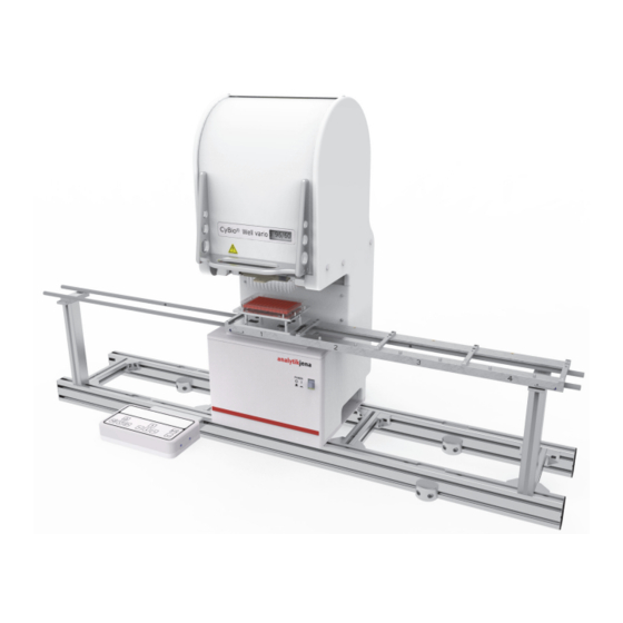
Technical Description Technical Description System Set-Up ® TheCyBio Well vario multi-channel pipettor is of modular design to facilitate different configurations for adaptation to a variety of customer applications. The system provides one essential advantage: only a few easy steps are required to replace the pipetting head or the capillary head with another head. Systems with a capillary head include a compressed air control unit attached to the frame. The tube for compressed air supply is connected to the terminal at the capillary head. In addition, two different transporting mechanisms are available: ® CyBio Well vario with linear transporting unit ® CyBio Well vario with circular transporting unit Linear transporting unit: The linear transporting unit is intended for motion of a 3-, 4- or 5-place carriage in one plane. A carriage place is able to transport a microplate, reservoir or a washing trough. Depending on the product configuration, a pipetting head can be replaced from a front position or a rearside position. Circular transporting unit: This transporting mechanism is able to provide single plane transportation of micro- plates, reservoirs and wash troughs on 10 places of a rotary table. The pipetting head can be replaced working from the system's rearside. Linear transporting unit: Circular transporting unit ® Fig. CyBio Well vario with linear (shown with stackers) and circular transporting unit ®... - Page 40 Technical Description ® The various functional units of the CyBio Well vario are shown in → Fig. 7 (version with linear transporting unit). Their functions are explained in the following chapters. ® Fig. General view of CyBio Well vario (head change from the front version) Basic unit Tip magazine Transport rails Pipetting head Nameplate/Connection values sticker Fig. Nameplate, connection values sticker Nameplate specifications: Manufacturer details Product designation details (type designation, tradename) Identification code (model/serial number) Year of manufacture Connection values sticker specification: ...
-
Page 41: Component Description
Technical Description Component Description 4.2.1 Basic Unit The basic unit contains four motors with functions as follows: Positioning motion of microplate in X- and Y-direction (2 motors) Lifter motion: – Raising a microplate into position under the pipetting head – Transferring a microplate into position under the pipetting head in X- and Y- direction as appropriate for a given microplate type (2 motors) – Placement of a microplate onto the carriage or rotary table (initial position) Carriage motion in horizontal direction along the transport rails or rotary motion of rotary table in horizontal direction NOTE Zero-position is correctly positioned as part of a system initialization routine. System version for head replacement from the front The main switch for turning system power on and off is located on the front of the ba- sic unit (→ see fig. 28). System version for head replacement from the back The main switch for turning system power on and off is located on the back of the basic ... - Page 42 Technical Description Fig. Operation control panel Triangle keys Cancel key LCD display (2-line, 40 characters long) Enter key Arrow keys Control keys have assigned functions as follows: Triangle keys Trigger lifter and carriage or rotary table motion Keys for triggering lifter motion For down-motion or up-motion of the lifter. If both keys are simultaneously pressed for a short while, the lifter will move fully down to its zero-position Keys for horizontal carriage or rotary table motion The effect on pressing of these keys depends on the current lifter position. Vertical position 0 mm: Horizontal motion to carriage places or rotary table places. Vertical position > 0 mm: 384X pipetting head: Motion to positions A1 to B2 for 1536 wells 96X pipetting head: Motion to positions A1 to B2 for 384 wells or to A1 to D4 for 1536 wells. Arrow keys For menu selection and parameter input Keys for menu selection: For moving through a menu in forward and backward direction Keys for parameter settings For changes in program parameters Enter key Confirms input or current process. ® Release: 2017 CyBio Well vario...
-
Page 43: Pipetting Heads
Technical Description Cancel key [ESC] Aborts a running program for motion, aspiration, dispensing or tip change (clamping). On pressing [ENTER], the microplate carriage will move to position 1 in initialization mode. When programming mode is currently set, this key will switch to the next highest menu level. 4.2.3 Pipetting Heads ® The CyBio Well vario multi-channel pipettor accepts different types of multi-channel pipetting heads for expedited and highly precise processing of microplates with 96/384/ 1536-well capacity. The system is equally suited for both types of microplates: shallow well and deep well. Pipetting head motion is powered by two motors with assigned functions as follows: Piston drive Clamping and releasing of magazine holder A pipetting head can easily and quickly be replaced either from the front or the back, depending on the product version, by manual action (→ see fig. 10). For more conve- nient removal or installation of a pipetting head, the head has a handle attached to it and the magazine adapter provides a recessed handle. Rails are located on the lateral sides of a pipetting head for guided installation or removal motion. For exchange of pi- petting head, → refer to page 85. The following types of pipetting head are optionally available: Pipetting head Volume 250 μl 60 μl 96-channel (piston) pipetting head 40 μl... - Page 44 Technical Description Fig. 10: Pipetting head with magazine adapter Rail Handle Pipetting head Magazine adapter ® Release: 2017 CyBio Well vario...
-
Page 45: Pipetting Head Cybio
Technical Description ® 4.2.4 Pipetting head CyBio Well vario 1536/8 μl ® Fig. 11: Pipetting head CyBio Well vario 1536/8 μl Pipetting head Serial number TipTray (1536) Identification Desig- Identifica- Material Drawing- Pos. 4, nation tion/Volume (Tips) number → Fig. 11 Fixed TipTray (1) S 1 μl Steel OL5021-24-588... -
Page 46: Capillary Head
Technical Description 4.2.5 Capillary head The capillary head includes a magazine holder for capillary magazines. The clamping motor fixes a capillary magazine. The capillary head also provides a terminal for connec- tion of the air supply tube (→ see fig. 12, → item 5). A jet of compressed air is applied to completely dispense a previously aspirated amount of liquid into a microplate. A gas- ket is provided at the bottom of the head to prevent lateral emergence of compressed air above the capillary magazine. The capillary head can be quickly and easily replaced, either from the system front side (front side) or its rearside (back side), depending on the particular product version (→ see fig. 12). For convenient removal from, or insertion into the system, the capillary head has a special handle. In addition, a recessed handle in the magazine adapter can be used as further aid. Rails mounted to the lateral sides of the capillary head provide for guided motion during removal or installation of the head. For replacement of the capillary head, → refer to page 85. Optionally available capillary magazines are: Capillary magazine Volumes 96 or 384 capillaries 25, 50, 100, 250, 500, 750, 1000 nL Table 6: Available choice of capillary magazines Fig. 12: Capillary head with magazine adapter Rail Handle... -
Page 47: Tip Magazine (Pipetting Head)
Technical Description 4.2.6 Tip Magazine (Pipetting Head) A tip magazine holds 96 or 384 pipette tips. It maintains the pipette tips in an airtight- sealed condition while a pipetting process is going on. In the event of a pipetting head replacement or with major idle periods of the system, affected pipette tips must be kept in special tip tray packages. ® Fig. 13: CyBio TipTray 4.2.7 Capillary Magazine (Capillary Head) A magazine contains 96 or 384 capillaries. A capillary consists of glass. This means that a sample will only make contact with this inert material. Depending on their assigned fixed volume, the various capillary tips have color codes (→ see fig. 14): Color code Volume White 25nL 50nL Yellow 100nL Green 250nL Blue 500nL Orange 750nL Violett 1000nL Fig. -
Page 48: Terminals
Technical Description 4.2.8 Terminals Located on the rear panel are the system terminals, interfaces and fuses (→ see fig. 16). Warning notes must be observed in all cases and replaced immediately on noticing damage (→ see fig. 15). Fig. 15: View of rearside panel Warning label Connector panel Information label Fig. 16: Connector panel (for head replacement from the front version) ® PSPL-SV, terminal for external device Terminal for CyBio Well vario line power inlet COM RS 232 (Sub-D socket, 9-pole) ® CyBio Well vario line fuse Terminal for operation control panel Nameplate with product specs CAN jack PSPL-SV, terminal for external device... -
Page 49: Compressed Air Control Unit With Vacuum Suction
Technical Description 4.2.9 Compressed Air Control Unit with vacuum suction For compressed air supply, oil-free compressed air of a maximum 5 bar (0.5 MPa; 73 psi) pressure must be available on site. The compressed air control unit is mechani- cally attached to the system frame. Customer Service personnel will connect the com- pressed air supply tube to the system via the compressed air control unit with vacuum suction (→ Fig. 17) and adjust the specified operating pressure of 1.72 bar (0.172 MPa; 25 psi). CAUTION Faulty pressure settings may damage the system! Pressure settings made by Customer Service personnel must not be changed! Make sure that the counterlocking nut below the setting wheel is properly tightened. In the event of damage that can be shown to result from unauthorized changes in operating pres- sure, Analytik Jena AG will refuse any liability! NOTE ® If the operating pressure setting is too small, the CyBio Well vario with capillary head may provide only restricted functionality and capabilities. Fig. 17: Compressed air control unit with switch for Capillary Wash Station vacuum suction Manometer Compressed air regulator... -
Page 50: Tip Wash Station 1536 Set
Technical Description Tip Wash Station 1536 Set 4.3.1 General Information The tip wash station consists of a – Washing trough with one inflow (green) and one outflow point (red) – Suction trough Wash trough Liquid inflow and liquid outflow are achieved with one peristaltic pump for each direc- tion (e. g. via TWS module). A tubing diagram of the tip wash station is shown in → Fig. 18. One peristaltic pump fills washing liquid into the wash trough. The washing liquid is suctioned away and the inner space of tips thus washed. The peristaltic pump for outflow direction has a certain pre-run and after-run phase. It runs at higher speed. This prevent overflow situations of the wash trough. A sensor* is mounted at the inflow tube directly above the storage bottle to monitor for proper delivery of clean washing liquid. If there is a break in washing liquid delivery, an error message will be generated by control software. Suction trough A tubing diagram of the tip wash station is shown in → Fig. 19. ® Release: 2017 CyBio Well vario... -
Page 51: Overview
Technical Description 4.3.2 Overview Fig. 18: Tip wash station - tubing chart Wash trough Peristaltic pump for outflow Outlet port Inflow tube (reagent vessel) Inlet port Tube sensor TWS module Outflow tube (waste tank, liquid drain) Peristaltic pump for inflow Tube rejector Fig. 19: Suction trough Vacuum set → refer to page 37 Compressed air control unit → refer to page 33 Suction trough (OL5021-14-600) ® CyBio Well vario Release: 2017... -
Page 52: Safety Notes
Technical Description 4.3.3 Safety Notes The following safety symbols are affixed on the TWS module: Safety symbol Meaning Comment There is danger of crushing or Warns of potential crush pinching! effects of human extremities due to mechanical motion Fig. 20: Warning symbols at the TWS module Danger Zones Fig. 21: Danger zones at TWS module Peristaltic pumps Do not place your hands or fingers into the peristaltic pump when open, includ- ing with objects as long as operation has not finished. ® Release: 2017 CyBio Well vario... -
Page 53: Components
Technical Description 4.3.4 Components Vacuum set with waste Flask 0.5 l Abb. 22: Vacuum set Vacuum unit – SUP, EXH, VAC Flask – VAC – Suction trough The vacuum unit consists of a vacuum pump and a waste bottle. Vacuum is applied to withdraw liquid from the suction trough and transfer it to the waste bottle. NOTE Keep track of the waste bottle fill level, in order to prevent overflowing. Drain this bottle at regular intervals. ® CyBio Well vario Release: 2017... - Page 54 Technical Description TWS Module The purpose of the TWS module is to deliver and aspirate liquid. The module has two peristaltic pumps that can be energized individually. Power supply is drawn from a companion pipettor or a power supply module. The pi- pettor or power supply module will carry a label with specified line voltage level. Operation control of the TWS module is accomplished by control software. Fig. 23: TWS module with two peristaltic pumps TWS module Tubing chart Peristaltic pumps Tube Tube fixator Lever NOTICE Aggressive acids, leaches or organic solvents may cause material damage! Installed tubing at the peristaltic pumps will come into direct contact with liquid being pumped. Make absolutely certain that selected tubing is resistant to acids, leaches and organic solvents! Tubes of silicon peroxide are included in standard delivery. NOTE You are advised to contact Analytik Jena AG in case of doubt as to the use of certain substances. ® Release: 2017 CyBio Well vario...
- Page 55 Technical Description Fig. 24: TWS module terminal points (rearside panel) Operating state indicator B 2 (BC) Outlet for connection of a barcode reader COM 1 Host PC ® COM 2 Host equipment (e. g. CyBio Well) COM 3 Next downline unit B 3 (PSPL) Power supply B 4 (SW) Switch output Peristaltic pumps Peristaltic pumps of type Masterflex Easy-Load are installed in the TWS module. One peristaltic pump delivers liquid into the tip wash station, one pumps liquid out of the tip wash station. Fig. 25: Peristaltic pump – closed and open Peristaltic pump, closed Peristaltic pump, open Tube fixed...
-
Page 56: Operation
Technical Description 4.3.5 Operation Operation control of the TWS module and, hence, the tip wash station is accomplished by control software. The pumps can be individually powered. NOTE To perform initial starting up, place the wash trough into liquid with little surface ten- sion. This warrants that the pipetting tips will be uniformly washed thereafter. Peristaltic Pumps: Insertion of Tubes CAUTION There is danger of crushing or pinching while the pump is in action. Terminate all currently running system programs or turn system power off before you begin work at a peristaltic pump. 1. Turn peristaltic pump lever to the left Pump is open. 2. Insert tube as required for the direction of liquid flow 3. Return lever of peristaltic pump into rightmost position. 4. Let right and left tube fixator snap in. Pump is closed and ready for operation. Fig. 26: Insert tube in peristaltic pump The direction in which a pump is running determines the direction in which liquid will ... - Page 57 Technical Description Fig. 27: Peristaltic pump at TWS module, direction of rotation and liquid flow ® CyBio Well vario Release: 2017...
-
Page 58: Function
Technical Description Function 4.4.1 Function with Pipetting Head ® The CyBio Well vario multi-channel pipettor is designed as a 96-well or 384-well simultaneously working dosing system to allow automatic processing of mi- croplates in chemical, biological and physical research laboratories. The system provides six basic functions which, on aggregate, offer a diversity of applica- tion options (→ refer to page 62). A pipetting head can also be quickly replaced with another one (→ refer to page 85). Available options are: Basic functions Explanation Dosing – Aspirates a specified volume of liquid from a trough – Dispenses previously aspirated liquid into a microplate (example) with additional stroke Pipetting – Aspirates slightly more than a predefined volume of liquid from trough (with additional stroke volume). – Discharges predefined volume, leaving residual volume in pipette tip (differential pipetting). – Dispenses residual volume, for example, into a trough Dispensing –... -
Page 59: Function With Capillary Head
Technical Description ® ® CyBio Well vario operation is controlled via CyBio Composer, a software facilitating easy and expeditious editing of specific laboratory routines. In addition, manual com- mands may be triggered from the operation control panel (→ refer to chapter 7.2.2). 4.4.2 Function with Capillary Head ® The CyBio Well vario with capillary head allows for concurrent compound transfer into dry microplates of small volume capacity (from 25 nL to 1000 nL). This works particular- ly well where small amounts of liquid must be transferred quickly and in parallel, for example, in: Compound management Compound (dry) storage Assay development, screening/HTS, ADME/Tox Genomics, proteomics, ... Dispensing stock is aspirated by capillary force. This means that 96 or 384 capillaries can be filled simultaneously using the effect of capillary force. In principle, a sample transfer consists of dipping the capillaries into the liquid of a source plate and blowing the contents of the capillaries into a target plate. Once the capillaries are submerged in the liquid of a source plate, capillary force aspi- rates liquid into the capillaries so the capillaries fill up "of their own accord". Dispens- ing is accomplished with a short jet of compressed air to transfer the contents of ... - Page 60 Technical Description ® Release: 2017 CyBio Well vario...
-
Page 61: Transportation & Storage
Transportation & Storage Transportation & Storage Transportation CAUTION Environmental influences, mechanical shocks or formation of condensed water may de- stroy individual system components! Adequate precautions should be taken to protect all components from environmental impacts, mechanical shock or formation of condensed water during transportation or shipment! Temporary open-air storage of the system is prohibited! CAUTION Transportation with the pipetting head still in place is likely to cause damage to the pi- petting head and the system! ® Do not transport the CyBio Well vario, unless you have removed the pipetting head! System transportation with a pipetting head still mounted will not be permissible. Failure to comply will void any claims for warranty and liability! CAUTION Improper packaging is likely to cause damage to the system! Use only original packing for transportation and shipment of the system and its acces- sories. To prepare the system for transportation, proceed as follows: 1. Remove tip magazine, then insert magazine adapter into pipetting head (→ refer to chapter 7.2.4). 2. Perform system shut-down (→ refer to chapter 10). ® 3. Deinstall pipetting head from the CyBio Well vario. 4. Use only original packaging for transportation. Contact your competent service partner for original packing items if necessary! 5. -
Page 62: Storage
Transportation & Storage Storage ® If the CyBio Well vario is not installed immediately after arrival of product shipment or is not required for a longer period of time, it should preferentially be stored in its origi- nal packing case. Climatic requirements on facilities for system storage are as follows: Temperature range: +10 °C to +50 °C Permissible relative air humidity:≤ 85 % at 30 °C, no formation of condensate ® Release: 2017 CyBio Well vario... -
Page 63: Initial Start-Up & Routine Start-Up Procedure
Initial Start-Up & Routine Start-Up Procedure Initial Start-Up & Routine Start-Up Proce- dure Site Requirements 6.1.1 Installation Requirements ® The room which is selected for CyBio Well vario installation must meet the following environmental requirements: Temperature range: +15 °C to +35 °C ≤ 75 % at 35 °C, non-condensing Permissible relative air humidity: The atmosphere inside the operating room should be dust-free to a maximum possible degree, free from drafts and free from etching vapors. You are prohibited from smok- ing in the operating room. For pipettor site selection, the following rules should be observed: The operating room must have a stable, horizontal, dry and vibration-free floor. Do not install the system directly at doors or windows nor close to sources of electromagnetic interference. Prevent direct exposure to sunlight and radiation emitted by heaters. Provide air conditioning for the room if necessary. ... -
Page 64: Energy Supplies
Initial Start-Up & Routine Start-Up Procedure 6.1.3 Energy Supplies WARNING In the event of a break in protective conductor wiring, there is life-threatening danger due to electrical shock! Insert the main power plug only into a mains socket with a grounded PE contact! Make sure that the protection effect is not rendered ineffective by extension cables without a PE conductor or by the use of a voltage regulating transformer! CAUTION Operation at a mains voltage level or frequency other than specified on the nameplate may result in destruction of the pipettor! Make sure that power supply specifications in the operating room agree with name- plate details! Refrain from start-up action of any kind if power supply data are inconsis- tent! ® The CyBio Well vario requires a single-phase AC power supply net for operation. Pow- er supply is factory-set to 230 V or 115 V and a frequency of 50/60 Hz. Make absolutely certain that nameplate specifications are actually met and power is supplied with values as indicated on the nameplate. 6.1.4 Compressed Air Supply (Only for Capillary Head) Connection of compressed air supply may be established by none other than the Cus- tomer Service of Analytik Jena AG or duly authorized expert personnel. Site require- ments: oil-free compressed air supplied with a maximum pressure of 4 to 5 bar (60-80 psi). CAUTION There may be system damage as a consequence of faulty operating pressure! Once set by Customer Service personnel at the pressure control unit, the operating pres- sure must not be changed! In the event of damage that must be ascribed to unautho- rized modification in operating pressure, Analytik Jena AG will not assume any liability! NOTE Too low settings for operating pressure may restrict the functionality and operating ca-... -
Page 65: Configuration & Start-Up
Initial Start-Up & Routine Start-Up Procedure Configuration & Start-Up In view of the complexity and to ensure failsafe system operation, work for installation ® and initial start-up of the CyBio Well vario on your premises is must be completely per- formed by Customer Service personnel of Analytik Jena AG or duly authorized expert technicians. Initial start-up essentially includes: Installation and adjustment of all system components Providing cable connections and connecting power supply cables Software installation (factory-performed) and configuration Briefing and on-the-job training Check for integrity, completeness and compliance with packing list as you unpack the product shipment. On completion of work for system installation, Customer Service personnel will perform checks for proper function, providing documented proof of successful testing (→ see section 6.3.1). Firmware update is required → “Current firmware version” on page 9. Function Tests 6.3.1 Precision Test Pipetting Head 96/384 Testing for variation coefficient (CV = per-centage standard deviation) is performed, us- ing a dye solution in a 96 well or 384 well microplate with flat transparent bottom. A ... - Page 66 Initial Start-Up & Routine Start-Up Procedure Always use new tips for precision measurement. Rinse new tips before measure- ment with p-nitrophenol working solution and settings as follows: Piston speed: 100 r.p.m. Number of rinse cycles: Rinsing volume: 10 μl ® Testing is performed with the CyBio Well vario in manual mode, using an aspira- tion volume of 20 μl or 10 μl (→ Table 9 on page 50), respectively, and a dispens- ing volume of 10 μl, 3 μl or 2 μl (→ Table 9 on page 50), respectively. Dispense the test volume into a microplate with prefilled NaOH solution (→ Table 8 on page 49). For test volume dispensing, the pipette tips should sub- merge into the prefilled NaOH solution by approximately 1 mm. Dispense the remaining volume into the storage reservoir. ® ®...
- Page 67 Initial Start-Up & Routine Start-Up Procedure Pipetting Head 1536 NOTE Residual liquid (in the tips) dab off on the station (if possible, ‘Pipetting’ mode). In any event, the tips should be swabbed before completion the pipetting / dispensing cycle (Composer: piston in the zero position; control panel: dab intermission). Avoiding disappearances by residual liquid. Testing for variation coefficient (CV = per-centage standard deviation) is performed, us- ing a dye solution in a 1536 well microplate with flat transparent bottom. A suitable vertical photometer is used for measuring. The photometer's own precision must be verified and documented according to manufacturer instructions prior to measurement. Materials & preparative action: 1536 well transparent flat-bottom microplate prefilled with 0.1 N NaOH vol- umes as follows: 7 μl NOTE A certain inhomogeneity in the rate of evaporation over a microplate will influence the result of testing adversely. For this reason, you should tape the microplates immediately after diluens has been filled in, after pipetting of the test volume and before shaking. Do not use washed mi- croplates. This may cause excessively great variation in measured values. Always use new tips for precision measurement. Rinse new tips before measure- ment with p-nitrophenol working solution and settings as follows: Piston speed: 100 r.p.m. Number of rinse cycles: 10 – 20 Rinsing volume: 5 μl ®...
- Page 68 Initial Start-Up & Routine Start-Up Procedure ® CyBio Well vario 1536 well/8 μl Aspiration volume 1 μl 1 μl Standard test volume 1.6 mM p-nitrophenol dye solution Select a dye concentration corresponding to an extinction between 0.5 and 0.8 OD at 405 nm. 2 Sigma 73560 Table 11: Aspiration and test volumes Tape the microplates after pipetting of the test volume and before shaking. Use an orbital shaker for mixing of substances. 1536-well microplate Orbital shaker of Shake for 10 min 1000 rpm Allow to rest for 30 to 45 min...
-
Page 69: Accuracy Test
Initial Start-Up & Routine Start-Up Procedure 6.3.2 Accuracy Test Accuracy defines the degree to which a measured dispensed volume (mean value of all readings measured for a 96 well, 384 well or a 1536 well microplate) is in agreement with a predefined (target) volume. Materials & preparatory action: Laboratory balance with 1 mg minimum resolution. The selected laboratory balance must be subject to regular calibration (check for calibration mark). Lidded 96 well, 384 well or 1536 well flat-bottom microplate. NOTICE Since new microplates, typically, are vacuum-packed, a selected microplate must be un- packed at least one week before testing (the weight of a new microplate may decrease or increase as a result of evaporation and absorption respectively). Accuracy testing is performed with de-ionized water (1 bar and 998 g/cm³). Test sequence Mount a reservoir with deionized water in a place on the carriage or the rotary table. Mount a microplate adapter in another place of the carriage or the rotary table. Moisten tips using a rinsing procedure as follows: number of cycles – 20, volume – 25 μl ® CyBio Well vario 1536: number of cycles 10 – 20, volume – 5 μl. -
Page 70: Leak Test
Initial Start-Up & Routine Start-Up Procedure 6.3.3 Leak Test Leak testing is required, in order to make sure that the pipettor head is free from points of leakage. Subject to testing are the pistons, the pipette tips and the silicon mem- brane. Testing is performed through aspiration of a certain volume of dye solution into the pi- petting tips and visually tracking the level of liquid over a time of two hours (96 wells) or using a different procedure for 384 well pipetting heads, which is described further below. Test sequence Make sure the system is in a horizontal position. Carefully place a spirit level onto the transport rails for this purpose. Use setting screws for horizontal adjustment as necessary. Remove old tips. Thoroughly inspect silicon membrane for cracks or sedimentation, using a suit- able light source. Carefully clean the silicon membrane using a dust-free, slightly moistened piece of cloth. Exert only moderate pressure, in order to prevent unwanted shifting of the membrane. Use caution to prevent sedimentation remaining in the membrane openings as you wipe the membrane clean. Allow the membrane to dry. Install tip magazine with new tips and clamp the tips. Bring the reagent reservoir into position under the tips. Raise the reagent reservoir to tips level — the pipette tips should submerge by at least 2mm below the surface of the test solution. Moisten the pipette tips on the inside by performing five rinse cycles. Aspirate 50 % (of end volume) of dye solution. NOTE Keep the pipette tips submerged during leak testing, in order to prevent formation of droplets at their ends, because droplets may falsify the result of testing. ... - Page 71 Initial Start-Up & Routine Start-Up Procedure Result of leak testing ® CyBio Well vario 96 There must be no perceivable difference in the filling height of the various pipetting tips on completion of testing. ® ® CyBio Well vario 384/CyBio Well vario 1536 There must be no individual variances ≥ 20 % on completion of testing. A drop in the fill level of a tip suggests a potential leak in this tip. First clean the sealing mat (removing dust, etc.). Repeat this test with new pipette tips. If the leak is found to occur in the same place, you should contact the manufacturer or your service partner. ® CyBio Well vario Release: 2017...
-
Page 72: Precision Test (Capillary Head)
Initial Start-Up & Routine Start-Up Procedure 6.3.4 Precision Test (Capillary Head) To perform precision testing, use the following procedure. Preparation To wet an inserted capillary magazine, use process settings as follows: Rinse cycles: Rinsing liquid: Water Aspiration 8 sec. by capillary force Submergence depth of 4 mm capillaries for aspiration Dispensing 1 sec. by pressure (25 psi, 1.72 bar) Dispensing gap: 1.5 mm NOTE This gap between the capillaries and the microplate must be kept in all cases. This pre- vents pressure-dispensed liquid from spurting out. Procedure: Allow 8 seconds for taking in p-nitrophenol (in DMSO) by capillary force. Then dispense ... - Page 73 Initial Start-Up & Routine Start-Up Procedure This requires initial concentration values as follows: Capillary magazine Initial concentration of p-nitrophenol (in DMSO) 25 nL 240 mMol 50 nL 120 mMol 100 nL 60 mMol 250 nL 24 mMol 500 nL 12 mMol 750 nL 8 mMol 1000 nL 6 mMol Precision testing may also be combined with fluorescence measurement. ® CyBio Well vario Release: 2017...
- Page 74 Initial Start-Up & Routine Start-Up Procedure ® Release: 2017 CyBio Well vario...
-
Page 75: Operation
Operation Operation ® Turning the CyBio Well vario On ® To turn the CyBio Well vario on, proceed as follows: ® 1. Check that CyBio Well vario power cord is correctly connected to the line power supply point. 2. For operation with a capillary head, check for proper setting of compressed air supply. Having installed the capillary head, connect the head's compressed air supply tube to its terminal point at the compressed air control unit 3. Transfer power on/off switch on the front panel (for front-side head replacement version) or the rear wall panel (for rear-side head replacement version) into posi- tion "I" (→ see fig. 28 and → Fig. 29). ® Once power is available, the CyBio Well vario is ready for action and can be operated in manual control or computer control mode. -
Page 76: Operating The Cybio
Operation ® Operating the CyBio Well vario from Control Panel 7.2.1 Overview of Menu Items Pipetting head The description in this section is restricted to manual control mode. For operating in- ® structions regarding PC mode and PC interface, you should consult the "CyBio Com- poser Plugin Pipettor“ user manual. ® The CyBio Well vario can be operated from the control panel which is located beside the system. Once system power is turned on, various menus will be available in manual control mode, each of which provides further options for selection and execution of sub-programs and system functions (→ see fig. 30 and → Fig. 31 respectively). Manual mode Configuration Statistics Changing head Fig. 30: Display screen – main menu Fig. -
Page 77: Fig. 32: Display Screen - Main Menu
Operation NOTE If you had been working in a sub-menu at the moment of turning power supply off, the same menu will be restored when power becomes available again. Capillary head Again, this section only describes manual control mode action. For instructions regard- ® ing PC operating mode and PC interface, you should refer to the "CyBio Composer Pl- ugin Pipettor" user manual. ® The CyBio Well vario can be operated from the control panel that is located beside the system. Once system power is turned on, various menus will be available in manual control mode, each of which provides further options for selection and execution of sub-programs and system functions (→ see fig. 30 and → Fig. 31 respectively). Manual mode Configuration Statistics Changing head Fig. 32: Display screen – main menu Fig. 33: Menu structure diagram view with capillary head Select a menu or submenu using ... -
Page 78: Menu [Manual]
Operation 7.2.2 Menu [Manual] Pipetting head Six basic functions are available in manual control mode: Dosing Pipetting Dispensing Diluting Tip change Rinsing Each individual action must be triggered by an operator. The advantage is convenience of operation. For example, manual mode provides a straightforward means for process- ing a single microplate. Dosing This basic function provides for aspiration of a specified volume of liquid and dispensing of this volume with additional stroke: 1. Select aspiration volume. Fig. 34: Display screen – dosing – aspiration volume 2. Move liquid-containg reservoir into position under the tips (trough, microplate). Trigger carriage or rotary table motion for this purpose, using as ... -
Page 79: Fig. 35: Display Screen - Dosing - Start
Operation Fig. 35: Display screen – dosing – start A preselected volume is aspirated in accordance with the setting for [dosage] function. For the time of aspiration, the lifter and carriage (ro- tary table) control unit is inactive. 4. To dispense an aspirated volume of liquid, move a microplate into position under the tips. ... -
Page 80: Fig. 38: Display Screen - Pipetting - Dispensing Volume
Operation Pipetting This basic function provides for aspiration of a greater volume of liquid, which is subse- quently dispensed. This is followed by ejection of the residual volume. This procedure allows for higher accuracy, because there is no residue of liquid on the inner wall of a tip, which otherwise has to be taken into account. 1. Select a dispensing volume. Fig. 38: Display screen – pipetting – dispensing volume 2. Select an aspiration volume. Fig. 39: Display screen – pipetting – aspiration volume Note: The preset value for aspiration is 2 μl above dispensing volume by default. It can, how- ever, be varied if necessary. 3. Move a container with liquid into position under the tips (trough, microplate). Trigger carriage or rotary table motion for this purpose, using or as necessary to reach the required position. Use to raise the lifter and use to lower the lifter. -
Page 81: Fig. 40: Display Screen - Pipetting - Start
Operation Fig. 40: Display screen – pipetting – start 5. Confirm your selection by pressing . This will trigger a pipetting process. A preselected aspiration volume is aspirated in accordance with [pipetting] function settings. During aspiration, the lifter and carriage (rotary table) control unit remains inactive. Fig. 41: Display screen – pipetting – aspiration volume 6. -
Page 82: Fig. 43: Display Screen - Pipetting - Residual Ejection
Operation 8. Use , key as necessary to bring a container for a residual ejection into position under the tips. 9. Confirm established position by pressing , in order to trigger a residual ejec- tion cycle. This will eject the differential amount of dispensing volume and aspira- tion volume and wait for a time, once started, as preset via configura- tion [Configuration] menu. -
Page 83: Fig. 46: Display Screen - Dispensing - Dispensing Volume
Operation Repeat this entry as many times as there are subvolumes to be processed. Fig. 46: Display screen – dispensing – dispensing volume 3. Select an aspiration volume. Note: The aspiration volume is preset to 2 μl above subsumed dispensing volume by default. It can, however, be varied if necessary. Fig. 47: Display screen – dispensing – aspiration volume 4. Move a container with dispensing stock into position under the tips (trough, microplate). Trigger carriage or rotary table motion for this purpose, using or as necessary to reach the required position. the lifter by pressing Raise , lower the lifter by pressing Note: With the lifter in raised position, you can set the following positions via or 96X pipetting head: Motion to positions A1 to B2 for 384 well operation or ... -
Page 84: Fig. 48: Display Screen - Dispensing - Start
Operation 5. Select [Start] menu item. Note: On selection of [Exit], you can exit the [Manual] menu without actually trigger- ing the process. Fig. 48: Display screen – dispensing – start 6. Confirm your selection by pressing , in order to trigger a dispensing cycle. The preselected volume is aspirated. During aspiration, the lifter and carriage (rotary table) control unit remains inactive. Fig. 49: Display screen – dispensing – aspiration 7. -
Page 85: Fig. 50: Display Screen - Dispensing - Ejection
Operation Fig. 50: Display screen – dispensing – ejection 9. Move a microplate into position under the tips for dispensing. To do this, trigger carriage or rotary table motion, using or as neces- sary to reach the required position. Raise the lifter by pressing , lower the lifter by pressing 10. Press keys , as required to bring a container into position under the tips for residual ejection. 11. Trigger residual ejection by pressing key The differential amount of a total dispensing volume and an aspirated volume is dispensed, once the cycle has started. -
Page 86: Fig. 53: Display Screen - Diluting - Number Of Volumes
Operation Diluting Aspirates two volumes separated by an air bubble in a preset mixing ratio and dispenses the two volumes with additional stroke. NOTE Depending on the type of pipetting head, the total of subvolumes must not exceed the maximum volume. 1. Enter a value for number of subvolumes. Fig. 53: Display screen – diluting – number of volumes 2. Enter aspiration volume settings. Fig. 54: Display screen – diluting – aspiration volume 3. Move a liquid-containing vessel into position under the tips (trough, microplate). To do this, trigger carriage or rotary table motion, using or as neces- sary to reach the required position. Raise the lifter by pressing , lower the lifter by pressing . ... -
Page 87: Fig. 55: Display Screen - Diluting - Start
Operation Fig. 55: Display screen - diluting - start 5. Use key for confirmation. This is necessary to trigger a dilution process. 6. To trigger aspiration of subvolumes, press key Note: Repeat this process as many times as there are subvolumes. Fig. 56: Display screen – diluting – aspiration 7. Move a microplate into position under the tips for ejection. To do this, trigger carriage or rotary table motion, using or as neces- sary to reach the required position. Raise the lifter by pressing , lower the lifter by pressing Note: With the lifter in raised position, you can set the following positions via or : 96X pipetting head: Motion to positions A1 to B2 for 384 well operation or ... -
Page 88: Fig. 58: Display Screen - Diluting - Dabbing Break
Operation bring the tips into a convenient position for dabbing. Once the break for dabbing has finished, the pistons will move into zero-position. Fig. 58: Display screen – diluting – dabbing break Tip change CAUTION There is danger of finger crushing/pinching and damage to pistons! The magazine plate is released and clamped with electro-motoric power. For a tip change, a magazine plate must be pushed in until hard stop position. Prevent physical contact with the magazine plate as the tips are automatically clamped! 1. Select tip change basic function in [Manual] menu. Magazine plate with pipette tips is automatically released. Fig. 59: Display screen – tip change – tip release 2. -
Page 89: Fig. 61: Tip Magazine Change (For Head Replacement From The Front)
Operation Fig. 61: Tip magazine change (for head replacement from the front) Magazine plate Pipette tips CAUTION There is danger of piston or system damage! Remember that only tip-filled magazines may be inserted and clamped! Insertion of a magazine is monitored by a microswitch. If a magazine is inserted in a non-conforming manner, an "Insert magazine (with tips)" prompt will appear. Should the microswitch fail to respond, pipettor parts, notably, the pistons may suffer damage. Shut the system down and promptly notify the manufacturer in this case. 3. Insert a magazine plate with tips until mechanical stop position. Make sure that the magazine uniformly sits on the frame at all points. If the magazine is found to be correctly seated, you can trigger a magazine plate clamping cycle. Note: If the magazine is not properly seated, the microswitch will be triggered and an "Insert magazine (with tips)" prompt appears on the screen. Fig. 62: Display screen – tip change – magazine insertion 4. Confirm clamped state by pressing key Fig. -
Page 90: Fig. 64: Display Screen - Rinsing - Number Of Rinsing Cycles
Operation Note: Once the magazine plate is fixed, the screen will display the menu in which a tip change was selected. Rinsing Aspirates or dispenses a specified volume of rinsing liquid in a defined order of rinsing cycles. 1. Enter a value for the number of rinsing cycles (maximum: 20). Fig. 64: Display screen – rinsing - number of rinsing cycles 2. Move a rinsing vessel into position under the tips for rinsing. To do this, trigger carriage or rotary table motion, using or as neces- sary to set the required position. To raise the lifter, use , to lower the lifter, use 3. Confirm established position by pressing key Fig. 65: Display screen – rinsing - volume 4. -
Page 91: Fig. 68: Display Screen - Rinsing - Dispensing
Operation Fig. 68: Display screen – rinsing - dispensing 5. In a dabbing break, you can press , as necessary to bring the tips into a convenient position for dabbing. On termination of the dab- bing break, the pistons will return to zero-position. Fig. 69: Display screen - rinsing - dabbing break Note: On completion of rinsing, the menu will appear in which rinsing was selected. Capillary head There are two basic functions available in manual mode: Dispensing Tip change Each individual action must be triggered by an operator. The advantage is convenience of operation. For example, manual mode provides a straightforward means for process- ing a single microplate. Dispensing A total volume that depends on the type of capillary is aspirated by capillary force. ... -
Page 92: Fig. 71: Display - Dispense
Operation Select the [dispense] menu item: This will display the following box: Dispensing Pos:1 Start Exit Changing tips Fig. 71: Display - dispense 1. Move a container with dispensing stock into position under the tips (trough, microplate). Trigger carriage or rotary table motion, using or as necessary to reach the required position. Raise the lifter by pressing and aspirate stock for dispensing. Lower the lifter again by pressing 2. Move a microplate into position under the capillary tips for dispensing. To do this, trigger carriage or rotary table motion, using or as neces- sary to reach the required position. Raise the lifter by pressing , lower the lifter by pressing You should also note the following: If a 96-channel capillary magazine has been inserted, a positional shift must be included for 384-well or 1536-well processing. The same applies in the case of 1536-well processing with a 384-channel capillary magazine. If this is not the case, continue with → item 4. Always define the type of plate to be processed in the [Configuration] => [Wells] menu (→ refer to page 81→ “Wells”). CAUTION Prevent damage to a capillary due to faulty settings for dispensing position. -
Page 93: Fig. 72: Display - Dispense With Position Selection
Operation Motion to positions A1 to B2 for 1536 well oper- 384X capillary maga- ation zine: Dispensing Pos:1A1 Start Exit Changing tips Fig. 72: Display - dispense with position selection 4. Select [Start] menu item. Note: On selection of [Exit], you can exit the [Manual] menu without actually trigger- ing the process. Dispensing Pos:1A1 Start Exit Changing tips Fig. 73: Display – dispensing – start 5. Confirm your selection by pressing , in order to trigger a dispensing cycle. ... -
Page 94: Fig. 75: Display - Tip Change - Magazine Removal
Operation Changing tips Remove tip magazine Fig. 75: Display – tip change – magazine removal Fig. 76: Capillary magazine change (version: head replacement from the front) Capillary magazine Capillary tips CAUTION Prevent damage to the system! Only capillary-filled magazines may be inserted and clamped! Insertion of a magazine is monitored by a microswitch. If a magazine is placed in a non-conforming manner, an "Insert magazine (with tips)" prompt“ will appear. Should this microswitch fail, the system may suffer damage. Shut the pipettor down and promptly notify the manufacturer in this case. 3. Insert a capillary magazine with tips until mechanical stop position. Make sure that the magazine is evenly seated on the frame. If the magazine is correctly placed, you may trigger an automatic magazine plate clamping cycle. Note: If a magazine is misplaced, the microswitch will be triggered and the screen display a ... -
Page 95: Menu [Configuration]
Operation 4. Confirm clamped state by pressing key Changing tips Tighten tips Fig. 78: Display – tip change – tightening of tips Note: Once the magazine plate is fixed, the screen will display the menu in which a tip change was selected. NOTE Please note the microplate settings when you perform a magazine change. NOTE A tip change can also be performed via [Dispense] menu (→ Fig. 71). 7.2.3 Menu [Configuration] Pipetting head Pipettor settings can be adapted to specific user or application requirements. This can be achieved via the [Configuration] menu: 1. Return to the main menu should the pipettor be working in a different sub- menu. 2. Use key or in the main menu to select the [Configuration] submenu. 3. Confirm your selection with the key. - Page 96 Operation Waiting time Because of the small opening of tips and the resulting resistance they offer to the flow of liquid, a reasonable time setting should be added to allow for pressure compensation during aspiration or dispensing cycles. Too small settings for waiting time may reduce precision. Note: A waiting time which is set in this menu will only be valid for manual mode. Table motion path For defining a maximum available length of table motion (lifter height). This setting pre- vents mechanical collision of a vessel with tips. It also facilitates different applications, for example, the picking up of liquid over a cell lawn or the pipetting onto the bottom of a microplate from a preselected distance. The height position can be adjusted in steps of 0.1 mm. CAUTION There is danger of tips suffering damage or getting destroyed! A value setting for lifter height will only be effective in manual mode so it may be ex- ceeded in software-controlled operation mode! For updating the vertical setting value for the lifter following necessary replacement of the lifter (setting value inscribed on lifter bottom on shipment). This will automatically correct vertical lifter adjustment so previously edited programs need not be changed in terms of height coordinates. ® Release: 2017 CyBio Well vario...
-
Page 97: Fig. 80: A1 Well Target Positions For 96/384/1536 Well Microplate
Operation Wells This option can be used to select a mode for manual lifter motion adapted to a given one out of various plate types (e.g. motion to positions of a 384 well microplate or a 1536 well microplate). The correct plate type must be set in order to guarantee that a tip is located in the middle of its companion well. Fig. 80: A1 well target positions for 96/384/1536 well microplate A1 well target position for 96 well microplate A1 well target position for 384 well microplate A1 well target position for 1536 well microplate The diagram view illustrates that the tips will come down onto the edge of wells in the event of wrong type setting. Example: If a 1536 well microplate were to be processed with a 96 tip magazine, the tip would come down in point 1 of figure 56. Solution: Set 1536 for plate type in the [Configuration] => [Wells] menu. Perform manual mo- tion to position A! for 1536 well microplates before dispensing (point 3 in Figure 56). This menu item is intended for storing internal XY correction values for lifter motion. In the event of necessary lifter replacement (according to manufacturer specification pro- vided on lifter underside), you can update your lifter settings here. Fig. 81: Display – XY correction values The first entries in a line indicate the direction. The coordinates for zero point (nn) cor- respond to those of a 96 well microplate. The path, however, represents the distance to a 384 well or 1536 well plate in the cor- responding coordinate direction (refer to details on underside of lifter). ... - Page 98 Operation Piston speed: Piston speed (pumping rate) is a selectable parameter. This setting will only be effective in manual mode, since programs running in PC-controlled mode include their own pre- viously stored pump speed values. A rotation speed of 300 r.p.m. corresponds to an ap- proximate dispensing rate of 123 μl/s achieved with a 250 μl pipetting head or a 12.3 μl/s rate achieved with a 25 μl pipetting head. You can enter an end value for motion speed here. Software settings can be made for end speed, or starting speed and end speed or for the motion characteristic. Table speed A table speed setting will be valid for lifter motion and carriage and rotary table motion. You can enter an end value for motion speed here. Software settings can be made for end speed, or starting speed and end speed or for the motion characteristic. CAUTION In the case of excessively high carriage or rotary table motion speed, there may be over- flow of liquid from the reagent troughs. Select a reasonably reduced speed value if nec- essary. NOTE In manual mode, lifter motion is limited to a maximum speed of 17 mm/s (60 r.p.m.). This is necessary to enable a more precise height setting. In program-controlled (com- puter-controlled) mode, the limiting value is around 40 mm/s (140 r.p.m.). Click Allows you to set an acoustic click for confirmation of each keystroke. You can switch the click on and off. ® Release: 2017 CyBio Well vario...
-
Page 99: Fig. 82: Display - Configuration Menu (Capillary Head)
Operation Capillary head Pipettor settings can be adapted to specific user or application requirements. This can be achieved via the [Configuration] menu: 1. Restores the main menu should the pipettor be working in a different submenu. 2. Use key or in the main menu to select the [Configuration] submenu. 3. Confirm your selection with the key. You are working in the [Configuration] menu now. Stage height Wells Stage speed Beep Exit Fig. 82: Display – configuration menu (capillary head) 4. Select appropriate parameter and enter desired values in [Configuration] menu, (refer to description below). Confirm each input by pressing ... -
Page 100: Fig. 83: A1 Well Target Positions For 96/384/1536 Well Microplate
Operation Wells This option can be used to select a mode for manual lifter motion adapted to a given one out of various plate types (e.g. motion to positions of a 384 well microplate or a 1536 well microplate). The correct plate type must be set in order to guarantee that a tip is located in the middle of its companion well. Fig. 83: A1 well target positions for 96/384/1536 well microplate A1 well target position for 96 well microplate A1 well target position for 384 well microplate A1 well target position for 1536 well microplate The diagram view illustrates that the tips will come down onto the edge of wells in the case of a faulty plate type setting. Example: Of a 1536 well microplate were to be processed with a 96 tip magazine, the tip would come down in point 1 of figure 56. Solution: Set 1536 for plate type in [Configuration] => [Wells] menu. Perform manual motion to A1 well position for 1536 well microplates before dispensing (point 3 in figure 56). This menu item is intended for storing internal XY correction values for lifter motion. In the event of necessary lifter replacement (according to manufacturer specification pro- vided on lifter underside), you can update your lifter settings here. Fig. 84: Display – XY correction values The first entries in a line indicate the direction. The coordinates for zero point (nn) cor- respond to those of a 96 well microplate. The path, however, represents the distance to a 384 well or 1536 well in the corre- sponding coordinate direction (refer to details on underside of lifter). ... -
Page 101: Menu [Head Change]
Operation Table speed A table speed setting will be valid for lifter motion, carriage motion and rotary table motion. You can enter an end value for motion speed here. Software settings can be made for end speed, or starting speed and end speed or for the motion characteristic. CAUTION With excessively high settings for carriage motion or rotary table motion, there may be overflow of liquid from the reagent troughs. Select a reasonably reduced speed value if necessary. NOTE In manual mode, lifter motion is limited to a maximum speed of 17 mm/s (60 r.p.m.). This is necessary to enable a more precise height setting. In program-controlled (com- puter-controlled) mode, the limiting value is around 40 mm/s (140 r.p.m.). Click Allows you to set an acoustic click for confirmation of each keystroke. You can switch the click on and off. 7.2.4 Menu [Head change] Replacement of the pipetting head or the capillary head can be performed in the [Head change] menu. Each individual action must be performed by an operator. Follow LCD screen prompts which are displayed at the operation control panel, and proceed step by step. CAUTION There is danger of crushing or pinching! Keep clear of the pipettor head's working and motion range, unless operation has stopped. Otherwise, there is high risk of physical injury. Notably, make sure that all protective covers and shielding panels are mounted and closed, as long as the "Remove head" prompt has not appeared. NOTE Mechanical motion of various system assemblies creates a crushing hazard for the hands of operating personnel! For this reason, the pipetting head top cover is monitored electronically. All electrically powered drives will stop immediately on opening of the cover. ®... -
Page 102: Fig. 85: Display - Main Menu
Operation NOTE If you had been working in a submenu at the moment of turning power supply off, the same menu will be restored when power becomes available again. This will also apply if a head change procedure was not completed. Head replacement from the front (only linear transporting unit) To perform head replacement for "from the front" system version, proceed as follows: 1. Press key or in the main menu as necessary to select the [Head change] menu, then confirm your selection with The magazine plate with pipette tips is automatically released. Fig. 85: Display – main menu 2. Remove tip magazine from pipetting head and store magazine in tip tray pack- age. Fig. 86: Display –... -
Page 103: Fig. 87: Remove Tip Magazine Or Capillary Magazine
Operation Fig. 87: Remove tip magazine or capillary magazine (from the front replacement version) 3. Use recessed handle to push the magazine adapter down into the pipetting head until mechanical stop position. Fig. 88: Display – head change – insert magazine adapter Fig. 89: Insert magazine adapter (head replacement from the front version) 4. Confirm magazine adapter inserted state by pressing key ... -
Page 104: Fig. 90: Display - Head Change - Clamp Magazine Adapter
Operation Fig. 90: Display – head change – clamp magazine adapter 5. Wait until prompt for removal of head appears, then confirm by pressing key . Fig. 91: Display – head change – remove head please CAUTION There is danger of crushing or pinching as cover is opened or closed! To open or close the cover, hold it at the handle with one hand! Keep the other hand clear of system space! 6. Hold the handle of the head cover with one hand, then tilt cover up until it engages mechanically. Fig. 92: Open cover (head replacement from the front version) CAUTION There is danger of crushing or pinching! A pipetting head weighs 14 kg, the capillary ... -
Page 105: Fig. 93: Retrieval Of Pipetting Head (From The Front Head Replacement Version)
Operation – Only for capillary head: Disconnect compressed air supply tube from con- nector terminal at the system, not at the head (→ see fig. 117). – Hold pipetting head at its handle with one hand. – Slightly raise the pipetting head. – Carefully pull the head off, supporting it with the other hand. Use recessed handle at magazine adapter bottom for this purpose. – Place pipetting head onto a stable support base. Fig. 93: Retrieval of pipetting head (from the front head replacement version) Handle Recessed handle at adapter bottom 8. To insert a new pipetting head or capillary head, proceed as follows: – Hold pipetting head at its handle with one hand. – Use the other hand for support as you push the pipetting head in. Use the recessed handle at magazine adapter bottom for this purpose. –... -
Page 106: Fig. 94: Insertion Of Pipetting Head (Head Replacement From The Front Version)
Operation Fig. 94: Insertion of pipetting head (head replacement from the front version) Handle Rail Red marker Recessed handle at adapter bottom CAUTION There is danger of crushing or pinching! For opening or closing, hold the cover at its handle with one hand! Keep other hand clear of system space during opening or closing motion! 9. Tilt cover down until it closes, then release cover. The cover locks by itself. The magazine adapter moves down and un- locks automatically. 10. Pull magazine adapter out of pipetting head from the front. Use recessed handle at magazine adapter bottom for this purpose. -
Page 107: Fig. 96: Removing Magazine Adapter (Head Replacement From The Front Version)
Operation Fig. 96: Removing magazine adapter (head replacement from the front version) CAUTION There is danger of piston or system damage! The pipetting head may only be loaded with magazines filled with tips or capillaries! In- sertion of a magazine is monitored by a microswitch. If a magazine is found to be wrongly inserted, an "Insert tip magazine" prompt will appear. Microswitch failure may result in damage to the system (notably, pistons). Shut power supply fully down and promptly notify the manufacturer in any such case. 11. Insert tip magazine into pipetting head until mechanical stop position. Fig. 97: Display – head change – insert magazine ® CyBio Well vario Release: 2017... -
Page 108: Fig. 98: Pushing Magazine In (Head Replacement From The Front Version)
Operation Fig. 98: Pushing magazine in (head replacement from the front version) 12. Confirm tip magazine clamped state by pressing key . Head replacement is complete. The system is ready again for operation. Head replacement from the back To perform head replacement for "from the back" version, proceed as follows: 1. Press key or in the main menu as necessary to select the [Head change] menu, then confirm your selection with Fig. 99: Display – main menu 2. -
Page 109: Fig. 101: Removal Of Tip Magazine (Head Replacement From The Back Version)
Operation Fig. 101: Removal of tip magazine (head replacement from the back version) 3. Use recessed handle to push the magazine adapter down into the pipetting head until mechanical stop position. Fig. 102: Display – head change – insert magazine adapter Fig. 103: Insertion of magazine adapter (head replacement from the back version) 4. Confirm magazine adapter inserted state by pressing key ... -
Page 110: Fig. 104: Display - Head Change - Clamp Magazine Adapter
Operation Fig. 104: Display – head change – clamp magazine adapter 5. Wait until prompt for removal of head appears, then confirm by pressing key . Fig. 105: Display – head change – remove head CAUTION There is danger of crushing or pinching as the cover is opened or closed! To open or close the cover, hold it at the handle with one hand! Keep the other hand clear of the system space! 6. Hold the handle at the back of the head cover with one hand, then tilt cover up until cover mechanically engages. Fig. 106: Opening the cover at the back of the pipettor ®... -
Page 111: Fig. 107: Removal Of Pipetting Head (Head Replacement From The Back Version)
Operation CAUTION There is danger of crushing or pinching! A pipetting head weighs 14 kg, a capillary head 10 kg. Always hold the pipetting head with both hands. 7. To remove the pipetting head, proceed as follows: – Only for capillary head: Detach intermediate connector of compressed air supply tube, do not detach connector at the head end (→ see fig. 117). – Hold pipetting head at its handle with one hand. – Slightly raise the pipetting head. – Carefully pull pipetting head off, using the other hand for support. Note: Use recessed handle at the bottom of the magazine adapter for this purpose. – Place pipetting head onto a stable support base. Fig. 107: Removal of pipetting head (head replacement from the back version) 8. To insert a new pipetting head, proceed as follows: –... -
Page 112: Fig. 108: Insertion Of Pipetting Head (Head Replacement From The Back Version)
Operation Fig. 108: Insertion of pipetting head (head replacement from the back version) CAUTION There is danger of crushing or pinching! To open or close the cover, hold its handle with one hand! Keep the other hand clear of the system space. 9. Tilt cover down until it closes, then release cover. The cover locks by itself. The magazine adapter moves down and un- locks automatically. 10. Pull magazine adapter out of pipetting head from the front. Use recessed handle at magazine adapter bottom for this purpose. Fig. 109: Display – head change – remove magazine adapter ®... -
Page 113: Fig. 110: Removal Of Magazine Adapter (Head Replacement From The Back Version)
Operation Fig. 110: Removal of magazine adapter (head replacement from the back version) CAUTION There is danger of piston or system damage! Insert only tip-filled magazines into the pipetting head! Insertion of a magazine is mon- itored by a microswitch. If a magazine is found to be wrongly inserted, an "Insert tip magazine" prompt will appear. A microswitch failure may result in damage to the system (notably, pistons). Shut power supply fully down and promptly notify the manufacturer in any such case. 11. Insert tip magazine into pipetting head until mechanical stop position. Fig. 111: Display – head change – insert magazine ® CyBio Well vario Release: 2017... -
Page 114: Special Functions
Operation Fig. 112: Insertion of tip magazine (head replacement from the back version) 12. Confirm tip magazine clamped state by pressing key. Head replacement is complete. The system is ready again for operation. 7.2.5 Special Functions CAUTION There is danger of damage to the system due to incorrect parameter settings, following a reset of operating parameters! Operating parameters are preferably set by the customer service of Analytik Jena AG! Before resetting an operating parameter and setting a new value by yourself, make sure you have consulted with the appropriate Analytik Jena AG customer service personnel at first! For powering-on, there are some option to generate special functions. The following functions will be available when you press the appropriate key during a procedure for powering on: Key ... - Page 115 Operation Key Resets all operating parameters Resets all system parameters, including drive parameters, to man- ufacturer values. On pressing of this key, the following system parameters must be set manually again. Drive parameters Are valid for powering of the pump motor (piston drive), the car- riage (rotable table) motor and the lifter motor: – Starting r.p.m. – End r.p.m. – Number of steps to reach end r.p.m. Operating parameters – Language – Waiting time – Maximum lifter height – Lifter height compensation dZ – Plate type selection (available for 96-well head operation only) – XY-table shift setting ® CyBio Well vario Release: 2017...
-
Page 116: Turning The Cybio ® Well Vario Off
Operation ® Turning the CyBio Well vario Off Pipetting head ® To turn the CyBio Well vario off, proceed as follows: ® 1. Wait until the CyBio Well vario has completed all work operations. ® 2. Use the main switch to turn the CyBio Well vario off. ® 3. Close CyBio Composer control software session if necessary and turn the PC off. ® The CyBio Well vario has been powered down. Capillary head ® To turn the CyBio Well vario off, proceed as follows: ®... -
Page 117: Specific System Details (Pipetting Head)
Operation Specific System Details (Pipetting Head) Aspiration and dispensing of liquid is accomplished by piston motion. All piston suspen- sion points have a mechanical freeplay (slackness). This means: After each reversal in piston motion direction, the piston drive initially covers a certain travel length without actually moving the pistons, and, hence, without aspirating or dispensing any liquid. This motion length corresponds to the freeplay. In order to prevent dosing errors, a volume cycle is organized in such a way that the pis- ton reversal point lies outside of the actual pipetting range (motion into zero-position, aspiration with additional stroke) or is corrected by suitable compensatory motion (dis- pensing with additional stroke). 7.4.1 Aspiration with Additional Stroke Fig. 113: Aspiration with additional stroke Zero-position A1 = D2: nominal pipetting volume Aspirate volume with A2: additional aspiration volume additional stroke and reverse D1: additional volume being dispensed piston direction < A2 (additional stroke) Upper freeplay D2: nominal pipetting volume Exactly dispense volume (single D3: residual volume (proportional to volume or partial volumes) freeplay) Residual ejection D4: air Move to zero-position... -
Page 118: Aspiration Without Additional Stroke
Operation direction reversal, an additional volume (D1) is dispensed. Due to piston reversal, this volume is smaller than the aspirated additional stroke volume (A2). The tip retains the nominal pipetting volume (D2) and a residual volume (D3). Exact volumes can be dispensed in the next step (4) (in a single step or a multi-step se- quence). After the nominal pipetting volume has been dispensed, the pipetting tip will contain the residual volume (D3) that results from upper direction reversal. This volume is dispensed with additional stroke (5) into a waste box or the reservoir. Since the stroke length is greater than actually required for the residual volume (D3), the residual vol- ume is completely dispensed. Finally, the amount of air is dispensed (D4). A volume cy- cle is completed by "Motion into zero-position". A "Move pistons into zero-position" command (6) triggers upward piston motion to their initial positions, thus excluding the lower freeplay. This process must be triggered with no liquid present, i.e. the lifter must be in such a position that the tips cannot make contact with liquid. Liquid which is aspirated in the process may result in dosing errors or contamination of pistons. 7.4.2 Aspiration Without Additional Stroke Fig. 114: Aspiration without additional stroke Zero-position A1=D1: nominal pipetting volume Aspiration D2: air Upper freeplay Dispense with additional stroke Move to zero-position Where liquid is aspirated without an additional stroke, it must be dispensed in a single step, in order to achieve precise results. This cycle must provide for a motion length that is greater for dispensing (4) than that for aspiration (2). Since the reversal point of pis- ton motion lies within the motion range that is covered by the pistons for dispensing, ® Release: 2017 CyBio Well vario... -
Page 119: Volume Cycle
Operation no volume is dispensed on excession of the upper freeplay (3). If dispensing motion cov- ers a motion length that is greater than actually required for a given nominal volume, the previously aspirated volume will be completely dispensed from the pipette tip, with subsequent dispensing of air (D2). A "Move pistons into zero-position" command (5) will move the pistons into their up- per initial positions thus excluding the amount of lower freeplay. This process must be triggered with no liquid present, i.e. the lifter must be in such a position that the tips cannot make contact with liquid. Liquid which is aspirated in the process may result in dosing errors or contamination of pistons. 7.4.3 Volume Cycle Standard cycle: Aspiration with additional stroke Dispensing (single volume or subvolumes) Residual dispensing Motion to zero-position Simplified cycle (only for dispensing of single volumes): Aspiration without additional stroke Dispensing with additional stroke Motion to zero-position 7.4.4 Waiting Time Piston motion always creates a state of underpressure or overpressure during an aspira- tion or a dispensing cycle. In order to maintain the specified system precision, pressure ... - Page 120 Operation The achievable degree of precision is limited and influenced by: the wettability of tips, the dimensional stability of their outlet opening, the way the system and involved liquids are handled. physical and chemical properties of liquid the quality of microplates You are also advised to note the following: NOTE Liquid is aspirated or dispensed as a result of underpressure or overpressure created by piston motion. In either case, the process will not be completed before pressure balance state has been reached. The time required to reach this state depends - among other factors - on the properties of the liquid being handled. For this reason, adequate pause times should be included with all operating sequences as necessary. NOTE When working with dry tips, pressure equalization of a different kind will occur after filling. It takes a longer to finish, because an air vapor pressure will build up in the air cushion inside the tip above liquid level, resulting in liquid emerging from the tips. This can be prevented by triggering a few initial rinse program cycles, until the air inside the tip is saturated with vapor. Even after a longer downtime with tips in filled condition, no liquid will emerge on completion of preventive rinsing. NOTE By wetting the tips with liquid, you may influence the achievable level of precision and accuracy. As a matter of importance, tips should therefore be submerged into the liquid volume just as much as necessary for a particular process. In addition, the depth of sub- mergence should always be the same in multi-cycle mode. This can be achieved by maintaining a constant reservoir filling level with the help of the sensor-controlled res- ervoir pump. NOTE For precise work results, you are advised to use a non-shedding slightly moistened scrubbing towel to dab the tips. You may place the towel onto a standard microplate (for example). ® Release: 2017 CyBio Well vario...
-
Page 121: Fault Removal
Fault Removal Fault Removal Malfunction or faults during operation will be displayed on the working screen. Where a fault situation was clearly caused by operator action, operation can be resumed, once the fault has been removed (turn power off and on again for greater safety). Check all potential fault sources on occurrence of a fault. If problems remain after this check or on identification of an undescribed fault, you should notify the Analytik Jena AG Customer Service or their authorized service partner. Error Messages ® The following fault messages may be displayed by the CyBio Composer software: Error/Error code Cause Action for removal Tip clamping device defec- Notify customer service tive Undefined head type Notify customer service RAM fault Notify customer service Tips are lose Turn power supply off and on again. Magazine not fully inserted Remove and insert magazine once again. Tip magazine of older make, Replace tip magazine or have back corners are not magazine reworked by rounded off. dealer/service personnel. Tip magazine edges or cor- Replace tip magazine or have ... - Page 122 Fault Removal Error/Error code Cause Action for removal Pump drive has reached You may be able to remove upper limit position. this error by performing an exchange of tips. Note: On repeated occurrence of this fault, repair work is nec- essary! Pump drive has reached You may be able to remove lower limit position. this error by performing an exchange of tips. Note: On repeated occurrence of this fault, repair work is nec- essary! The lifter cannot find its Turn power supply off and internal lower zero position. on again. Note: Repair work is necessary if error occurs repeatedly. Error by external device, Turn power supply off and (plate transfer unit, drip- on again. catcher) Note: Repair work is necessary if error persists. Host computer triggered ...
- Page 123 Fault Removal Error/Error code Cause Action for removal Internal bus error Turn power supply off and on again. Note: Notify customer service if error occurs repeatedly. Safety circuit interrupted Check safety circuit of exter- (special system configura- nal devices. tion). Error by external device Notify customer service Error on float-point opera- Turn power supply off and tion on again. Note: You should notify the cus- tomer service on repeated occurrence of this error. Table 13: Error code table ® CyBio Well vario Release: 2017...
- Page 124 Fault Removal In addition, the following faults may occur: Error message Cause Action for removal No aspiration allowed at The system tries to aspirate Correct program sequence this point. a volume, following an as necessary. aspiration or a dispensing cycle, despite the fact that the pistons have not yet returned to their zero- positions. Aspirated volume too Aspirated volume is too Valid values are within the small. small. range of 0.1 μl - 25 μl or 2 μl - 250 μl, depending on the type of pipetting head. Correct these values accordingly. Command requires more Command was transferred Check transfer cables for parameters. to pipettor with some proper condition. required parameters miss- Check that available soft- ing.
- Page 125 Fault Removal Error message Cause Action for removal Wrong parameters Software transferred Check that available soft- wrong parameters to sys- ware version is actually tem. configured for your system (refer to Hardware system information window in [Devices]) menu. Check system connections for proper state. On failure to remove this error, you should notify the customer service. Error on calculating motor Value settings for system Correct parameter settings characteristic. motor characteristic are as necessary. unrealistic. Error on communicating Interface transmission Check PC and system for with interface error which cannot be proper connection. located in greater detail. Check configuration of serial interface and PC. Error on horizontal drive Horizontal motion was ...
- Page 126 Fault Removal Error message Cause Action for removal ® System not operational System currently unable to Press a key at the CyBio accept commands. If this Well vario and try again. error occurs during a pro- gram start, a program was typically cancelled while the system waited for a key-press signal. Failure to find internal System was unable to find Perform an change of tips. zero-position of piston the zero-position for pis- Repair work is necessary if motion drive. ton motion. this error persists. No tip magazine available System failed to detect a Insert a tip magazine if no tip magazine. tip magazine available. Remove and reinsert tip magazine if a magazine had been installed. ® No or faulty communica- Data transfer to table con- Turn CyBio Well vario ...
- Page 127 Fault Removal Error message Cause Action for removal Illegal command Transfer cables are in a Check transfer cables for non-conforming state. proper condition. Software version not con- Check that available soft- figured for your system. ware version is actually configured for your system (refer to Hardware system information window in [Devices]) menu. On failure to remove this error, you should notify the customer service. Communication aborted User break of currently running program Microplate size not sup- System displays microplate Notify customer service ported by software size that is not supported and request software ver- by software. sion that is matched to this sys- tem version. Program memory location Reports attempted storage Delete program number, not free of a program in a location ...
- Page 128 Fault Removal Error message Cause Action for removal Sum of volumes too great The sum of all volumes Correct setting values aspirated and dispensed is appropriately. too great. Valid values are within the range of 2 μl to 250 μl. On adding all signed cycle values up with each other, this range must not be exceeded. Sum of volumes before The sum of volumes aspi- Correct setting values and after block is unequal rated and ejected in a cur- appropriately. zero rent block (program, combined commands, repeat modules) is unequal zero. On adding all cycle values up with each other, their sum must equal zero within a given block. Text too long Text which is intended for Shorten output text. output to the system dis- play is too long.
- Page 129 Fault Removal Error message Cause Action for removal Volume too small The sum of all volumes Correct setting values aspirated and dispensed is appropriately. too small. Valid values are within the range of 2 μl to 250 μl. If all signed cycle values are added up with each other, the result must not be below the lower limit of this range. Capillary head does not Blocked or broken capillar- Replace clogged or broken dispense in a conforming capillaries (→ see section manner. 9.2.5) No air supply or faulty con- Check air supply. In the troller setting of com- event of controller misad- pressed air control unit. justment at the com- pressed air control unit, restore the correct operat- ing pressure (→ “Technical Specifications”). Capillary head does not ...
-
Page 130: Errors By Compressed Air Control Unit (Capillary Head)
Fault Removal Errors By Compressed Air Control Unit (Capillary Head) Fault Cause Action for removal No pressure at out- Fixed opening clogged. Replace component or fixed put. opening (customer service). Compressed air leak- Dust in sealing part of main Remove dust from valve seat age at outlet opening valve by replacement of seat com- ponent or by cleaning of valve guide (customer service) Membrane has a defect Replace membrance (customer service) ® Release: 2017 CyBio Well vario... -
Page 131: Maintenance & Care
Maintenance & Care Maintenance & Care Safety Notes WARNING Note that contact with voltage-carrying system parts may lead to physical injury or even death! Turn system power off and detach power cable from the line socket before you proceed to any kind of maintenance or care! Make sure that the system is protected from acci- dental restoration of power! Operating personnel are prohibited from performing work for maintenance, repair or adjustment of voltage-carrying system parts! Maintenance, repair or adjustment of sys- tem modules under electrical voltage may only be carried out by a qualified electrician! CAUTION Penetrating liquid may cause material damage to electrical and electronic components! Make sure that no liquid can penetrate into the inner space during any kind of work for maintenance or care. NOTE ® Intervention into mechanical or electronic parts in the inner CyBio Well vario space may not be performed by anyone other than customer service personnel or specially au- thorized expert technicians. ® To ensure that your CyBio Well vario preserves optimal adjustment condition and will faultlessly function over a longer period of time, we recommend the conclusion of a ser- vice/maintenance contract with Analytik Jena AG. Maintenance and care work items should be performed on a regular basis at specified intervals (refer to table → page 116, observing these general rules: Never use cleaning powder, paint thinners or solvents like petrol or acetone to clean the system! These substances will attack the surface of shielding and cover panels (→ “Chemical Resistance” on page 20). ... -
Page 132: Maintenance Work
Maintenance & Care NOTE Dirt, e.g. dried-on liquid, may increase wear dramatically in some cases. Always main- tain clean working conditions! Maintenance Work 9.2.1 Overview The following table lists required maintenance and care work items with related period- icities. Maintenance action Maintenance interval Weekly Monthly Half-yearly Clean transport rails with carriage or rotary table Use mild cleaning agent or disinfectant to clean the tip washing trough Wash tubing Replace used tips Clean tip magazine, autoclave magazine if necessary (pipetting head) Check filter of compressed air control unit for condensate level and drain if necessary (only for systems with capillary head) → see section 9.2.9 Clean all liquid-holding vessels and the outside of tubes with disinfectant Clean tubes with disinfectant or autoclave tubes Inspect sealing plate (pipetting head) for clean condition ® Release: 2017 CyBio Well vario... -
Page 133: Lubricating Transport Rails (Linear Transporting Unit)
Maintenance & Care Maintenance action Maintenance interval Weekly Monthly Half-yearly Inspect carriage or rotary table for visible damage and clean as necessary – Remove tip magazine – Turn power off – Remove microplates or reservoirs Only linear transporting unit – Take carriage off and clean with mild cleaning agent or disinfectant – Mount carriage again Inspect lifter for damage and clean if nec- essary Perform precision test (→ refer to page 49) Perform leak test (→ refer to page 54) Check electrical components and cabling, test grounding (PE) conductor (only quali- fied electrician!) Check and clean compressed air control unit (Customer service personnel only) Table 15: Maintenance intervals The piston sealing components are subject to strong wear and tear, conditional upon ... -
Page 134: Cleaning The Lifter
Maintenance & Care 9.2.3 Cleaning the Lifter NOTE XY-lifter motion must not be obstructed by unwanted objects. Otherwise, the life time of motors will diminish significantly. Contamination and natural wear of modules give rise to increased strain levels and, hence, an increased probability of failure. Check for signs of wear and tear on assem- blies under mechanical strain and initiate necessary replacements promptly on identify- ing wear and tear. Check lifter for dirt at regular intervals. Clean if necessary. 9.2.4 Tip Magazine (Pipetting Head) CAUTION Direct contact of the tip magazine and the pistons may damage the pistons. Never install a tip magazine without tips into the pipettor! A tip magazine inserted with no tips installed will void any warranty claims! NOTE Before system down-times of several hours or several days, the tips should be unclamped. The tip magazine must remain installed in any such case. ® Operating the CyBio Well vario in manual or automatic mode, you should carefully watch for and remove residual air bubbles from the tips. Otherwise, the liquid in affect- ed tips will reach an excessively high fill level. There is danger of pistons coming into contact with liquid and suffering contamination in such cases. This may happen if liquid is drawn from vessels with insufficient filling level or if tips are not introduced deep enough. Make sure that pistons cannot come into contact with liquid during motion into zero- position. Repeated faulty operation may lead to excessively high fill levels and a situa- tion of the kind as described above. ® Release: 2017 CyBio Well vario... -
Page 135: Replacement Of Capillaries
Maintenance & Care 9.2.5 Replacement of Capillaries Toolset A set of tools is available for replacement of capillaries or adjustment of their glass tips. Fig. 115: Toolset Allen key for replacement of capillaries Special tool for adjustment of glass tips Replacing capillaries in capillary magazine CAUTION Glass capillaries are fragile! There is danger of physical injury from glass splinters! Proceed with adequate caution when replacing a capillary cassette or individual capil- laries! Keep capillary magazines always in the storage box. This is necessary to prevent damage to capillaries. To replace a capillary, proceed as follows: 1. Select [Manual] => [Tip change] in the menu: Dispensieren Spitzenwechsel Verlassen 2. Retrieve the capillary magazine, once it has been released. Spitzenwechsel Magazin entfernen 3. Place the capillary magazine into its storage box. The box provides a safe place of storage so individual capillaries can be replaced without any risk of breakage. 4. -
Page 136: Cleaning The Carriage (Linear Transporting Unit)
Maintenance & Care 5. Install the capillary magazine back into the capillary head and press "Enter" key at the control panel. The capillary magazine will be clamped again. Spitzenwechsel Spitzen anziehen Its capillaries have been replaced. 9.2.6 Cleaning the Carriage (Linear Transporting Unit) NOTE Carriage performance depends on the current state of the transport rails. Remove pock- ets of dirt, contamination or damage of transport rails immediately. To clean the carriage, proceed as follows: ® 1. Turn CyBio Well vario power off at the main power switch, then disconnect the power plug from the socket. 2. Remove tip magazine from pipetting head for safety reasons (→ refer to page 117). 3. Remove all microplates, reservoirs or washing troughs. 4. Remove carriage from the transport rails by raising it at the front and the back end by equal amounts simultaneously. Proceed with due care, in order to prevent damage. -
Page 137: Sealing Plate (Pipetting Head)
Maintenance & Care sure that tip magazine is correctly placed on completion of work. ® 6. Reconnect power plug to mains socket and turn CyBio Well vario power on at the main switch. The system will be re-initialized and becomes operational again. 9.2.8 Sealing Plate (Pipetting Head) NOTE Where pipette tips are changed at shorter intervals, fine fluff-ball stock or dust may set- tle on the sealing plate, thus impairing the efficiency of sealing. You are advised to follow these rules: 1. Do not use pipette tips covered with dust. 2. Check sealing plate for cleanness once in a month. 3. Trigger a tip changing cycle and remove the tip magazine for inspection and cleaning. The sealing plate can now be accessed from the bottom. Use a non- shedding slightly moistened cloth for cleaning. 4. Proceed with utmost caution in order to prevent unwanted position-shifting of the sealing plate. Otherwise, there is danger of plate openings getting clogged with fluff balls. 5. Do not remount the tips, until the sealing mat has fully dried. 9.2.9 Compressed Air Control Unit –... - Page 138 Maintenance & Care ® Release: 2017 CyBio Well vario...
-
Page 139: Shutting Down
Shutting Down Shutting Down CAUTION There is danger of injury and damage to the pipettor if cables are removed before power is turned off! Do not remove cables as long as they are energized! Make absolutely certain that power supply has been cut before you remove a cable! ® If the CyBio Well vario is not required for a longer period of time, perform shut-down action as described hereafter: 1. Remove the tip magazine and place it into the tip tray package or remove the capillary magazine and place it into its special storage box. 2. Install plate adapter in the head. 3. Trigger a head change routine (→ see section 7.2.4) to remove the head from the system. 4. Only for capillary head: Detach compressed air tube from connector of com- pressed air control unit. Leave short tube end connected to the head. Fig. 117: Disconnectible air supply inlet 5. Transfer power switch into position "0". 6. Only for capillary head: Turn compressed air supply off and drain the system space until pressure-relieved state is achieved. - Page 140 Shutting Down NOTE A sub-menu you had been working in when power was turned off will be restored when power becomes available again. ® Release: 2017 CyBio Well vario...
-
Page 141: Accessories & Spare Parts
Accessories & Spare Parts Accessories & Spare Parts 11.1 Pipetting Heads & Pipette Tips NOTE The pipettor and its accessories are factory-matched to each other. Use only accessories recommended by the manufacturer. The manufacturer will refuse any warranty in the event of damage or function failure as a result of system operation with unspecified accessory items. ® For CyBio Well vario pipettor operation, the following accessory and spare part items are available (depending on purchased product version): Pipetting heads Ordering code number (exchangeable from the front) ® CyBio Well vario 2.5 μl pipetting head 96-fs OL3381-24-230 ® CyBio Well vario 25 μl pipetting head 96-fs OL3381-24-730 ® CyBio Well vario 40 μl pipetting head 96-fs OL3381-24-750... -
Page 142: Capillary Magazines
Accessories & Spare Parts Tip magazines (single-use tips) for 96-well and 384-well pipetting heads ® CyBio Tip magazine 250 μl DW (only 96-well pipetting head) ® CyBio Tip magazine 250 μl SW (only 96-well pipetting head) ® CyBio Tip magazine 60 μl SW ® CyBio Tip magazine 25 μl SW ® CyBio Tip magazine 10 μl SW Pipette tip magazines (ceramic tips) for 96-well and 384-well pipetting heads ®... -
Page 143: Further Accessories
Accessories & Spare Parts 11.3 Further Accessories ® Available accessories for CyBio Well vario operation are: Stacker and Microplate adapter Tip Wash Station, Capillary Wash Station Barcode reader Peristaltic pumps Plate transfer unit Reagent cooling system Tip changer Reservoirs Adjustment magazine 96 and 384 for Capillary Head Tube support chain for all Tip Wash Stations and Capillary Wash Stations Capillary Toolset (→ refer to chapter 9.2.5) NOTE Detailed information about available accessories can be contained directly from Analytik Jena AG or visiting us on the Internet at www.analytik-jena.com. ® CyBio Well vario 8 μl pipetting head 1536 Consumable materials Designation Volume... - Page 144 Accessories & Spare Parts ® Release: 2017 CyBio Well vario...
-
Page 145: Waste Disposal
Waste Disposal Waste Disposal 12.1 Consumables and Reagents NOTE Consumable materials must be disposed in accordance with binding workplace safety and environmental provisions of law. NOTE Biological samples must be treated in accordance with locally binding regula- tions for the handling of infectious material. Hazardous substances and related containers may not be disposed as domestic waste nor be allowed to penetrate into a sewage system or the soil. The appro- priate rules and practices must be closely followed for disposal of such sub- stances. 12.2 Instrument & Accessories NOTE The instrument, including any of its components, must be diposed in accordance with currently binding regulations of law on termination of use. Action of disposal will be re- sponsibility of the instrument owner. The legal basis for disposal procedures are these EC Directives and the related rules for implementation in national legislations within the EC: EC Directive 2002/95/EC (RoHS) EC Directive 2002/96/EC (waste electrical and electronic equipment) ® CyBio Well vario Release: 2017... - Page 146 Waste Disposal ® Release: 2017 CyBio Well vario...
- Page 147 ® CyBio Well vario System NOTICE ® This User Manual Supplement provides an overview of the CyBio Well ® vario system as a whole. It is only valid if used in combination with CyBio Well vario and Stacker User Manuals. For specific information regarding the various ® modules, you are referred to the relevant descriptions in CyBio Well vario (→ refer to page 1) and Stacker User Manuals.
- Page 148 ® Release: 2017 CyBio Well vario...
-
Page 149: Cybio Well Vario System
® CyBio Well vario System ® ® A CyBio Well vario system consists of a CyBio Well vario with a linear 4-position or 5- position carriage and not less than one stacker that can be located on the right-hand side or the left-hand side of the system. A stacker allows a large amount of microplates to be stored and processed in an efficient manner. The microplates are directly supplied ® by the transporting unit of the CyBio Well vario. Per stacker one peristaltic pump (for filling of reservoirs) and one barcode reader may be connected. The fill level of reser- ® voirs is monitored by fill level sensors. One CyBio Well vario is able to supply two ® stackers and one external module with electric power. CyBio Composer software con- ® trols CyBio Well vario system operation. For specific stacker information, you should consult the "Stacker" User Manual. A 1.1 Overview Because of its modular setup, the system is available in a variety of configurations. To ® ® provide an example of CyBio Well vario system configuration a CyBio Well vario with linear transporting unit (5 positions) and two stackers (with peristaltic pump) is shown below. ® Fig. -
Page 150: A 1.2 Technical Specifications
A 1.2 Technical Specifications NOTE For specific performance details of the various modules, you are referred to the appro- ® priate user manuals of the CyBio Well vario (→ refer to chapter 2) and the stacker. ® A 1.2.1 Phys. Dimensions & Weight Details of CyBio Well vario System With 2 Stackers CAUTION The system is designed as a desk-top device. Make sure the laboratory bench has ade- quate load-bearing capacity (compare with weight specifications) before you install the system. Phys. dimensions Max. width 1640 mm Height with stackers (standard version) 850 mm Depth 445 mm Weight... -
Page 151: A 1.3 Safety Notes
A 1.3 Safety Notes NOTE ® You are also advised to follow all safety notes (→ refer to chapter 3) in the CyBio Well vario User Manual and the Stacker User Manual. Fig. 119: Warning notes and safety devices Stop-and-Down pushbutton for Warning label at pipetting head stacker Warning note at barcode reader Warning text at peristaltic pump and warning text Warning notes at stacker lifter A 1.3.1 Mechanical Hazards ® Fig. 120: Danger zones of CyBio Well vario system Lifter of stackers Lifter of pipettor Peristaltic pump... -
Page 152: A 1.4 Product Versions
A 1.4 Product Versions Possible combinations are: Name Number of ® Number of CyBio stackers Well('s) ® Stacker — CyBio Well ® CyBio Well — stacker ® Stacker — CyBio Well — stacker EXT — system A 1.4.1 Setup Versions Possible setup versions are: close location (in relation to pipetting module) remote location (in relation to pipetting module) Fig. 121: Setup versions on base frame Base frame Mounting plate for pump module (accessory item) and extension module (accessory item) ®... -
Page 153: A 1.5 Installation & Startup Procedures
A 1.5 Installation & Startup Procedures NOTE ® Work for installation and initial start-up of the CyBio Well vario system may not be per- formed by anyone other than service personnel of Analytik Jena AG or that of specifi- cally authorized contractors. A 1.5.1 Cabling Diagram ® Fig. 122: Cabling diagram of a CyBio Well vario system with 2 stackers and extension module ® CyBio Well vario Release: 2017... -
Page 154: Fig. 123: Direction Of Rotation And Delivery Of Liquid For
A 1.5.2 Tubing Reservoir filling station The pump for reservoir filling is located at the stacker. The pump's direction of rotation determines the direction in which liquid will be transported (→ Fig. 123). Fig. 123: Direction of rotation and delivery of liquid for peristaltic pump at the stacker "Fill" command: The rollers of the peristaltic pump rotate clockwise. This means that liquid is pumped from the left to the right. The left tube end must be submerged in the reagent vessel while the right tube end connects to the reservoir. A 1.5.3 Inserting a Tube Into the Peristaltic Pump CAUTION There is danger of crushing or pinching while the pump is in action. Terminate all currently running system programs or turn system power off before you begin work at a peristaltic pump. -
Page 155: A 1.6 Operation
A 1.6 Operation A 1.6.1 Operating Modes ® The following operating modes are available when working with a CyBio Well vario system: Working with manual control unit (→ refer to chapter 7.2): – Manual mode – Configuration – Statistics ® PC-controlled operation (refer to; Plugin Pipettor Software ManualCyBio Com- poser) A 1.6.2 PC Mode PC interface ® Data transfers between the CyBio Well vario, stackers, additional modules and the control computer are accomplished via a serial RS-232C interface. Characters are of uneven parity, each consisting of 8 data bits and 2 stop bits. This data format cannot be changed. -
Page 156: A 1.7 Maintenance & Care
® Pin assignments at the CyBio Well vario ® Fig. 126: Pin assignments of 9-pole D-Sub jack (CyBio Well vario) Pin assignments at stacker Fig. 127: Pin assignments of 9-pole D-Sub jack (stacker) A 1.7 Maintenance & Care NOTE ®... - Page 157 Error/Error code Cause Action for removal System fails to work Mains plug not properly Insert mains power plug despite availability of connected to mains socket correctly. power supply, display or the system's combi- remains dark. seal. Mains socket is de-ener- Use other mains socket. gized. System inlet fuse is defec- Pull mains plug and replace tive. inlet power fuse. (make sure that fuse rating matches specifications at the system or quoted on → page 9 of chapter "Techni- cal Specifications") System reports "tip maga- Tip magazine of older Replace tip magazine. zine not inserted" error. make/back corners are not rounded. Tip magazine edges or Replace tip magazine. corners deformed result- ing from drop impact. Carriage fails to reach ...
- Page 158 ® Release: 2017 CyBio Well vario...
-
Page 159: Declaration Of Safeness
Declaration of Safeness Hereby I/we certify that the insides and outsides of the device described below (inclusive of all supplementary equipment and accessories) have been cleaned and disinfected and are free of any infectious, radioactive or otherwise hazardous or toxic substances, and that no risk or danger is involved in servicing the device. Name/Description: __________________________________ Serial number: _________________ __________________________________ Place, date Signature, name and company Person responsible for operating the above device: __________________________________ ® CyBio Well vario Release: 2017... - Page 160 ® Release: 2017 CyBio Well vario...
- Page 161 Index Index Dispensing . . . . . . . . . . . .42, 43, 66, 75 Dispensing with additional stroke . . .102 Accessories . . . . . . . . . . . . . . . . . . . 125 Disposal . . . . . . . . . . . . . . . . . . . . . .129 Additional stroke . . . . . . . . . . . . . . 101 Dosing . . . . . . . . . . . . . . . . . . . . .42, 62 Adjustment magazine . . . . . . . . . . . 127 dZ . . . . . . . . . . . . . . . . . . . . . . . .80, 83 Air humidity . . . . . . . . . . . . . . . . . . . 47 Arrow keys . . . . . . . . . . . . . . . . . . . . 26 Aspiration with additional stroke . . 101 Energy supplies . . . . . . . . . . . . . . . . .48 Aspiration without additional stroke 102 Enter key . . . . . . . . . . . . . . . . . . . . . .26 Error code . . . . . . . . . . . . . . . . . . . .105 Error message . . . . . . . . . . . . . . . . .108 Base frame . . . . . . . . . . . . . . . . . . . 136 Error removal ...
- Page 162 Index Scope of delivery . . . . . . . . . . . . . . . . .4 Sealing plate . . . . . . . . . . . . . . . . . .121 Maintenance . . . . . . . . . . . . . . . . . 140 Serial number . . . . . . . . . . . . . . . . . . . III Maintenance & care . . . . . . . . . . . . 115 Setup versions . . . . . . . . . . . . . . . . .136 Maintenance action . . . . . . . . . . . . 116 Shutting down . . . . . . . . . . . . . . . . .123 Maintenance interval . . . . . . . . . . . 116 Site requirements . . . . . . . . . . . . . . . .47 Maintenance work . . . . . . . . . . . . . 116 Source plate . . . . . . . . . . . . . . . . . . . .43 Mechanical hazards . . . . . . . . . . . . 135 Spare parts . . . . . . . . . . . . . . . . . . . .125 Menu Special functions . . . . . . . . . . . . . . . .98 Configuration . . . . . . . . . . . . . . . 79 Head change . . . . . . . . . . . . . . . . 85 Specific system features . . . . . . . . . .101 Menu items ...
- Page 163 TWS module . . . . . . . . . . . . . . . . 35, 38 Danger zones . . . . . . . . . . . . . . . 36 Terminals . . . . . . . . . . . . . . . . . . 39 Vacuum suction . . . . . . . . . . . . . . . . 33 Ventilation devices . . . . . . . . . . . . . . 18 Volume cycle . . . . . . . . . . . . . . . . . 103 Volumes . . . . . . . . . . . . . . . . . . . 27, 30 Waiting time . . . . . . . . . . . . . . . 80, 103 Warranty & liability . . . . . . . . . . . . . . . 3 Washing liquid . . . . . . . . . . . . . . . . . 34 Washing trough . . . . . . . . . . . . . . . . 40 Weight . . . . . . . . . . . . . . . . . . . . . . 134 Wells . . . . . . . . . . . . . . . . . . . . . 81, 84 XY . . . . . . . . . . . . . . . . . . . . . . . 81, 84 ® CyBio Well vario Release: 2017...
- Page 164 ® Release: 2017 CyBio Well vario...
Need help?
Do you have a question about the CyBio Well vario OL3381-25-300 and is the answer not in the manual?
Questions and answers