
Related Manuals for Analytik Jena AS 10e


Summary of Contents for Analytik Jena AS 10e
- Page 1 Service Manual AS 10e (from serial number: X67AU0001 and higher) AS 21hp (from serial number: X68AU0001 and higher) Sampler for TOC analyzers...
- Page 2 Analytik Jena GmbH Service Konrad-Zuse-Str. 1 07745 Jena Germany Phone + 49 3641 77 7402 + 49 3641 77 7449 Email service@analytik-jena.com http://www.analytik-jena.com General information B (06/2021) Issue Analytik Jena GmbH Implementation of technical documentation © Copyright 2021, Analytik Jena GmbH...
-
Page 3: Table Of Contents
Dismounting into the service position ................12 Exchange of Z-drive ......................16 Exchange of X-drive (carrousel guide) ................17 Final test of the sampler AS 21hp (AS 10e) ............19 Self-initialization ......................19 Test with service program ....................20 Rack detection ......................... 23 Test of magnetic stirrer (only AS 21hp) ................. - Page 4 Internal block diagram ....................... 7 Fig. 4 AS 10e / AS 21hp bottom side ..................8 Fig. 5 AS 10e / AS 21hp mounting plate complete ..............8 Fig. 6 AS 10e / AS 21hp description main board ................ 9 Fig. 7 Main board with Z-drive ....................
-
Page 5: Device Configuration
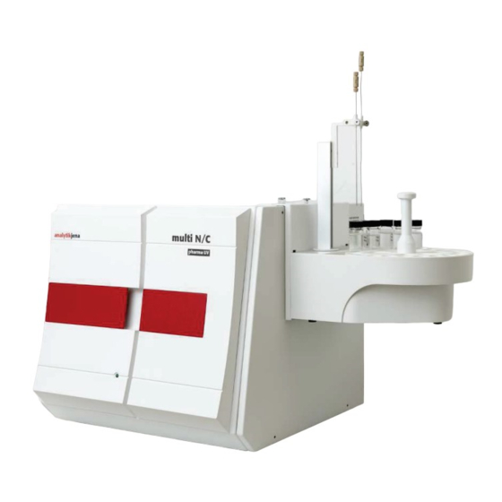
AS 21hp, AS 10e Device configuration Device configuration The auto-sampler AS 21hp (AS 10e) will be used in combination with: multi N/C 3100 (N3-500 and higher) multi N/C pharma UV multi N/C pharma HT multi N/C UV HS It communicates by RS 232 interface to the firmware controller of the main unit (analyzer), which controls its operation. -
Page 6: Power Supply
Canula holder Power supply The AS 21hp (AS 10e) will be supplied by an external power supply with 24 V DC (110 to 230 V AC/24 V DC). On the pcb main board are internal power regulators for process control (firmware... -
Page 7: Block Diagram
AS 21hp, AS 10e Device configuration Block diagram The internal structure will be displayed in the next schema (internal block diagram) Fig. 3 Internal block diagram... -
Page 8: Mechanical Structure
Mechanical structure AS 21hp, AS 10e Mechanical structure Fig. 4 AS 10e / AS 21hp bottom side Fig. 5 AS 10e / AS 21hp mounting plate complete X-drive bearing Motor X-drive Main board... -
Page 9: Fig. 6 As 10E / As 21Hp Description Main Board
AS 21hp, AS 10e Mechanical structure Fig. 6 AS 10e / AS 21hp description main board Optical sensor with plug X10: Z-sensor Motor X-drive 10 X8: not used X15: magnetic stirrer (only AS 21hp) 11 X1: not used SV2: not used... -
Page 10: Fig. 7 Main Board With Z-Drive
Mechanical structure AS 21hp, AS 10e Fig. 7 Main board with Z-drive X6: Z-OUT 2B (motor) X6: Z-OUT 1B (motor) X6: Z-OUT 2B (motor) X6: Z-OUT 1B (motor) Fig. 8 Bearing X-drive with sensor Circlip Bearing housings Drive bearing Screw M2,5x16... -
Page 11: Fig. 9 Z-Drive (Magnet Sensor)
AS 21hp, AS 10e Mechanical structure Fig. 9 Z-drive (magnet sensor) Screw M3x14 3x screw M2,5x6 Z-drive cover Z-drive mounting Z-drive housing... -
Page 12: Dismounting And Reassembling
Dismounting and reassembling AS 21hp, AS 10e Dismounting and reassembling Dismounting into the service position Remove the sampler from the main unit (analyzer). Lift-up the sampler carousel (sample tray) from the sampler. Loosen 5 screws on the rear side. -
Page 13: Fig. 12 Disassembly Of The Bottom Plate
AS 21hp, AS 10e Dismounting and reassembling Fig. 12 Disassembly of the bottom plate For mechanical work you can disconnect the interface and power supply cable from the main board (SV1). Fig. 13 Revision position of the sampler The sampler is now in revision position for measurements and tests. -
Page 14: Fig. 14 Removing The Cover Ring Of Z-Arm
Dismounting and reassembling AS 21hp, AS 10e Fig. 14 Removing the cover ring of Z-Arm Loosen 2 x M2.5x16 screws and remove the canula holder (Z-arm). Remove the protecting ring. -
Page 15: Fig. 15 Removing The Mounting Plate From The Housing
AS 21hp, AS 10e Dismounting and reassembling Fig. 15 Removing the mounting plate from the housing Loosen the two screws and remove the mounting plate completely from the housing. Fig. 16 Service position of sampler The sampler is now in its service position to exchange one of the drives. -
Page 16: Exchange Of Z-Drive
Dismounting and reassembling AS 21hp, AS 10e Exchange of Z-drive Move the sampler into the service position. Fig. 17 Unplugging the electrical connector from the main board (exchange of Z-drive) Unplug the Z-sensor cable (X10) and the Z-motor cable (X6). -
Page 17: Exchange Of X-Drive (Carrousel Guide)
AS 21hp, AS 10e Dismounting and reassembling Loosen the 2 screws with an Allen key (1.5 mm) and remove the Z-drive. The reassembling of the Z-drive will be done in reverse order. Perform the final test according to chapter 4. -
Page 18: Fig. 20 Loosening The Screws Of Tray Sensor
Dismounting and reassembling AS 21hp, AS 10e Fig. 20 Loosening the screws of tray sensor Loosen the 2 two screws M3,5x12 and remove the tray sensor tray. Loosen the 4 screws with an Allen key (2 mm) and remove the bearing X-drive with sensor. -
Page 19: Final Test Of The Sampler As 21Hp (As 10E)
AS 21hp, AS 10e Final test of the sampler AS 21hp (AS 10e) Final test of the sampler AS 21hp (AS 10e) Perform the following test after each service activity (exchange/adjustment/ maintenance): Self-initialization (see chapter "Self-initialization" p. 19). Initialization with service program with command <I>. -
Page 20: Test With Service Program
Final test of the sampler AS 21hp (AS 10e) AS 21hp, AS 10e Test with service program Connect the sampler by using the RS 232 interface with the service program (PC) via a Null modem cable (see Fig. 22). -
Page 21: Fig. 23 Configuration Of Service Program
AS 21hp, AS 10e Final test of the sampler AS 21hp (AS 10e) Start the service program with the "geraetetest.exe". Select the interface in the configuration. Fig. 23 Configuration of service program Select sampler with the menu point D ... -
Page 22: Fig. 25 Reading Firmware Version (Service Program)
Final test of the sampler AS 21hp (AS 10e) AS 21hp, AS 10e Read out the firmware version with command <V>. Fig. 25 Reading firmware version (service program) The answer is V_ … and is depending on the sampler type and its features:... -
Page 23: Rack Detection
AS 21hp, AS 10e Final test of the sampler AS 21hp (AS 10e) Rack detection The rack detection will be realized with specific positions of magnets on the bottom side of the tray. During the process of initialization the tray turns around and the positions of magnets will be detected. -
Page 24: Commands For Operation
Commands for operation AS 21hp, AS 10e Commands for operation Report-Commands Show state Qxy Bit0 not used Bit0 error Bit1 not used Bit1 not used Bit2 new switch on Bit2 sampler stop Bit3 busy Bit3 not used Identification rack Txy... -
Page 25: Initial Setup Of As 21Hp (As 10E)
S AS V EVICE CHOICE AMPLER ARIO Start the communication. Set <ROSA11> for AS 10e or <ROSA12> for AS 21hp. Fig. 27 Initial setup of sampler Select the rack type with S AMPLE ACK CHOICE ... -
Page 26: Fig. 28 Adjustment Of Sample Position
Commands for operation AS 21hp, AS 10e For adjustment of the sample position (see Fig. 2 on page 6: hole in sample tray) set <GJT>. Fig. 28 Adjustment of sample position Enable R for movement of the rack for left/right. -
Page 27: Troubleshooting
AS 21hp, AS 10e Troubleshooting Troubleshooting Problem/error message Affected component/reason How to solve? (multiWin) No or incomplete self- Power supply or socket of power Check of power supply (24 V DC) initialization supply Exchange the power supply (multiWin: Error 13) ... - Page 28 Troubleshooting AS 21hp, AS 10e Problem/error message Affected component/reason How to solve? (multiWin) No movement of carousel Check of movement to position 1 no movement exchange of motor for carousel or main board Carousel does not reach position 1 ...
-
Page 29: Spare Parts
Needle guide AS vario (two needles) 702-808.807 Power supply 24 V/50 W 702-827.065 Linear actuator, spindle:l=168 702-827.075 Spindle nut for NEMA 8 702-890.814 Z-drive AS vario 702-890.815 BG-Z coupling AS-F/-FD/-GF/vario 702-890.821 Main board AS 10e - programmed 702-890.822 Main board AS 21hp - programmed...
Need help?
Do you have a question about the AS 10e and is the answer not in the manual?
Questions and answers