
Subscribe to Our Youtube Channel
Related Manuals for Moxa Technologies WDR-3124A


Summary of Contents for Moxa Technologies WDR-3124A
- Page 1 WDR-3124A User’s Manual First Edition, May 2015 www.moxa.com/product © 2015 Moxa Inc. All rights reserved.
- Page 2 WDR-3124A User’s Manual The software described in this manual is furnished under a license agreement and may be used only in accordance with the terms of that agreement. Copyright Notice Copyright © 2015 Moxa Inc. Reproduction without permission is prohibited.
-
Page 3: Table Of Contents
Installing a SIM Card ........................... 1-9 Device Mounting ..........................1-9 DIN-Rail Mounting ........................1-9 Wall Mounting (optional) ......................1-10 Grounding the WDR-3124A ......................1-11 Wiring the Redundant Power Inputs ..................... 1-12 Wiring the Relay Contact ......................1-12 Wiring the Digital Inputs ......................1-12 Communication Connections ...................... - Page 4 Status ............................. 3-46 Wireless Status ......................... 3-46 DNS Information ........................3-46 SIM Status ..........................3-46 GPS Status ..........................3-47 Network Status ......................... 3-47 Associated Client List (for AP mode only) ..................3-48 DHCP Client List (for AP mode only) ..................... 3-48 System Log ..........................
-
Page 5: Introduction
802.11n and cellular technologies to offer greater flexibility in implementing wireless networks. The WDR-3124A is designed to operate at temperatures ranging from 0 to 55°C for standard models and -30 to 70°C for wide temperature models, and is rugged enough for any harsh industrial environment. -
Page 6: Overview
2.4 or 5 GHz bands and is backwards-compatible with existing 802.11a/b/g/n deployments to future-proof your wireless investment. Package Checklist The WDR-3124A is shipped with the following items. If any of these items is missing or damaged, please contact your customer service representative for assistance. •... -
Page 7: Product Specifications
WDR-3124A Introduction Product Specifications Cellular Interface Standards: GSM/GPRS/EDGE/UMTS/HSPA Band Options: • Five-band UMTS/HSPA 800/850/900/1900/2100 MHz • Quad-band GSM/GPRS/EDGE 850/900/1800/1900 MHz HSPA Data Rate: • Downlink: Up to 14.4 Mbps • Uplink: Up to 5.76 Mbps (Category 6, 7) GPRS Data Rate: Downlink/Uplink: 236 kbps (Class 12) - Page 8 WDR-3124A Introduction 5 GHz 802.11a: Typ. 20±1.5 dBm @ 6 to 24 Mbps Typ. 19±1.5 dBm @ 36 Mbps Typ. 16±1.5 dBm @ 48 Mbps Typ. 15±1.5 dBm @ 54 Mbps 802.11n: MCS0, 8 @ 20MHz: Typ. 19 dBm (± 1.5 dBm) MCS0, 8 @ 40 MHz: Typ.
- Page 9 WDR-3124A Introduction Interface Cellular Antenna Connector: 1 SMA (female) for WCDMA Wireless Antenna Connectors: 2 RP-SMA (female) GNSS: 1 SMA (female), GPS (1575.42 MHz), GLONASS (1602 MHz) Ethernet: 4, 10/100/1000Mbps auto negotiation speed, F/H duplex mode and auto MDI/MDI-X connection...
- Page 10 Details: See www.moxa.com/warranty ATTENTION • The WDR-3124A is NOT a portable mobile device and should be located at least 20 cm away from the human body. • The WDR-3124A is NOT designed for the general public. A well-trained technician should be enlisted to...
-
Page 11: Appearance
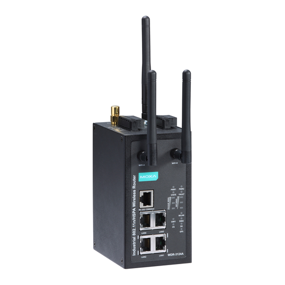
WDR-3124A Introduction Appearance GPS antenna connector (female SMA) Cellular antenna connector (female SMA) Grounding screw (M5) Terminal block (two digital input and one digital relay) Terminal block (PWR1 and PWR2) WIFI antenna ports (female RP-SMA) RS-232 serial console (RJ45) LED display... -
Page 12: Device Dimensions
Introduction Device Dimensions Connecting the Hardware This section describes how to install SIM cards in the WDR-3124A, mount the WDR-3124A on a DIN-rail or a wall, and connect the WDR-3124A to a computer for the first time. Wiring Requirements ATTENTION Safety First! Be sure to disconnect the power cord before installing and/or wiring your device. -
Page 13: Installing A Sim Card
There are two ways to mount the WDR-3124A: DIN-rail mounting and wall mounting. DIN-Rail Mounting The DIN-rail kit is attached to the back panel of the WDR-3124A. Mount the WDR-3124A on corrosion-free mounting rails that meet the EN 60715 standard. -
Page 14: Wall Mounting (Optional)
3. Lift up to remove the WDR-3124A from the DIN rail. Wall Mounting (optional) For some applications, it may be more convenient to mount the WDR-3124A to a wall. The following figure shows the DIN-rail kit dimensions (unit = mm (inch)). -
Page 15: Grounding The Wdr-3124A
WDR-3124A Introduction 2. Mounting the WDR-3124A to a wall requires 4 screws. Use the WDR-3124A device, with wall mount plates attached as a guide, to mark the correct locations of the 4 screws. The heads of the screws should be less than 6.0 mm in diameter, and the shafts should be less than 3.5 mm in diameter, as shown in the figure at the right. -
Page 16: Wiring The Redundant Power Inputs
The top two pairs of contacts of the 10-contact terminal block connector on the WDR-3124A’s top panel are used for the WDR-3124A’s two DC inputs. Top and front views of the terminal block connector are shown here. 1. Insert the negative/positive DC wires into the V-/V+ terminals. -
Page 17: Communication Connections
TRD(3)- Serial Connection The WDR-3124A has one RS-232 (8-pin RJ45) console port located on the front panel. Use either an RJ45-to-DB9 or RJ45-to-DB25 cable to connect the WDR-3124A’s console port to your PC’s COM port. You may then use a console terminal program to access the WDR-3124A for console configuration. -
Page 18: Led Indicators
WDR-3124A Introduction LED Indicators The following table describes the LEDs on the front panel of the WDR-3124A. Color State Description Front Panel LET Indicators (System) PWR1 Green Power is being supplied from power input 1. Power is not being supplied from power input 1. -
Page 19: Beeper
If the SIM LED is blinking after the WDR-3124A is powered on for several minutes, check the following: • PIN code • SIM installation If the 2G, 3G, and Cellular Signal LEDs are off after the WDR-3124A is powered on for several minutes, check the following: • APN information •... -
Page 20: Getting Started
Getting Started When setting up the WDR-3124A for the first time, the first thing you should do is configure its IP address. This chapter describes how to configure the IP address and describes the various configuration options. The following topics are covered in this chapter: ... -
Page 21: Static And Dynamic Ip Addresses
WDR-3124A Getting Started Static and Dynamic IP Addresses Determine whether your WDR-3124A needs to use a static IP address or dynamic IP address (either DHCP or BOOTP application) on the network. • If your WDR-3124A is used in a static IP environment, you must assign a specific IP address using one of the tools described in this chapter. -
Page 22: Ssh Console
WDR-3124A Getting Started SSH Console When using SSH client (e.g., PuTTY), run the client program (e.g., putty.exe) and then input the WDR-3124A’s IP address, specifying 22 for the SSH connection port. Serial Console You can access the WDR-3114A through the serial console for configuration. The configuration options and instructions are the same as if you were using the Telnet console. - Page 23 7. The Console login screen will appear. Log into the RS-232 console with the login name (default: admin) and password (default: root, if no new password is set). 8. The WDR-3124A’s device information and Main Menu will be displayed. Please follow the description on screen and select the administration option you wish to perform.
-
Page 24: Web Console Configuration
Web Console Configuration The web console is the most user-friendly method available to configure the WDR-3124A. With a standard web browser, you can easily access all settings and options. This chapter describes the configuration options and screens in the web console. The same configuration options are also available through the Telnet and serial consoles. -
Page 25: Accessing The Web Console
5. You may need to wait for a few moments for the web page to load on your computer. Note that the model name and IP address of the WDR-3124A are shown in the title bar of the web page. You... -
Page 26: Overview
The following figure shows an example. To activate the changes click Restart and then Save and Restart after you change the settings. It may take up to 30 seconds for the WDR-3124A to complete the reboot procedure. Overview The Overview page displays a summary of the current WDR-3124A status. -
Page 27: Sim Status
WDR-3124A. System Info Settings Specifying the device information on the System Info page makes it easier to identify the WDR-3124A on your network. Information (especially the device name and description) on the System Info page is displayed and included on the Overview page, in SNMP information, and in notification emails. -
Page 28: Network Settings
IP address Identifies the WDR-3124A on the LAN or WLAN network. 192.168.127.254 Subnet mask Identifies the type of network to which the WDR-3124A is 255.255.255.0 connected (for example, 255.255.0.0 for a Class B network, or 255.255.255.0 for a Class C network). -
Page 29: Time Settings
WDR-3124A Web Console Configuration Time Settings You can synchronize the system time on the WDR-3124A based on an NTP (Network Time Protocol) server or user-specified date and time information. The WDR-3124A includes the system time in system logs. NOTE The WDR-3124A includes a built-in real time clock (RTC). We strongly recommend that you update the... -
Page 30: Cellular Settings
SIM 1/2 ppp config Select Enable to configure PPP authentication manually. Otherwise, select Disable. SIM 1/2 ATD Enter the number the WDR-3124A uses to dial onto the data *99***1# network. This number varies depending on your country. SIM 1/2 ppp Select a PPP authentication method (Auto, PAP, or CHAP). -
Page 31: Guaranlink
With the GuaranLink feature, the WDR-3124A automatically tries to re-establish a connection when a connection failure has occurred. The WDR-3124A performs one of the following actions, depending on the number of enabled SIM cards: • One SIM card – Resets the cellular module without rebooting the device to force negotiation between the WDR-3124A and the base station. - Page 32 Register to network This field is used for ISP initial connection check. timeout Enter the time (10 – 600 minutes) the WDR-3124A is to wait before terminating connection to an ISP and starts the GuaranLink recovery process. PPP retry count Enter the number of times (1-5) the WDR-3124A is to establish a PPP connection to the ISP before restarting.
-
Page 33: Gps Settings
Web Console Configuration Field Description Default setting Packet-level Enter the number the WDR-3124A is to try the connection check in connection check 15 seconds before re-establishing the connection. retry count Transmission If a remote system regularly monitors connection to the... -
Page 34: Oncell Central Manager Settings
WDR-3124A. Manager IP Enter the public IP address for the OnCell Central server. Auto reconnect Specify the time (10 – 1000 seconds) the WDR-3124A is to wait period before re-connecting to the OnCell Central server. Management Enter the port number to send status information to the OnCell... -
Page 35: Wireless Settings
Web Console Configuration Service Forwarding In AP mode, you can configure service forwarding to allow up to eight devices connected to the WDR-3124A to connect to the OnCell Central server. In the navigation panel, click Cellular Settings > OnCell Central Manager Settings > Service Forwarding to display the configuration screen. -
Page 36: Operation Mode
This field is available in AP mode. Enable Select Enable to activate the RF (radio frequency) module. Operation mode Select AP to set the WDR-3124A to operate as a wireless access point. Select Client-Router to set the WDR-3124A to operate as a wireless client router. - Page 37 A/N Mixed – Sets the WDR-3124A to operate in IEEE 802.11a/n modes. In IEEE 802.11n mode, the WDR-3124A may operate at a lower speed when IEEE 802.11a clients are on the network. N Only (5 GHz) – Sets the WDR-3124A to operate in 5 GHz IEEE • 802.11n mode.
-
Page 38: Wlan Security Settings
Web Console Configuration Site Survey (Client mode only) When you set the WDR-3124A to operate in Client-Router mode, you can click Site Survey in the Basic Wireless Settings screen to search for available APs nearby. The following figure shows the search result. You can click an SSID to view detailed information. To scan and update the AP list, click Refresh. - Page 39 When WEP is enabled as a security mode, the length of a key (so-called WEP seed) can be specified as 64/128 bits, which is actually a 40/104-bit secret key with a 24-bit initialization vector. The WDR-3124A provides 4 entities of WEP key settings that can be selected to use with Key index. The selected key setting specifies the key to be used as a send-key for encrypting traffic from the AP side to the wireless client side.
- Page 40 Even though AES encryption is only included in the WPA2 standard, it is widely available in the WPA security mode of some wireless APs and clients as well. The WDR-3124A also supports AES algorithms in WPA and WPA2 for better compatibility.
- Page 41 WDR-3124A Web Console Configuration Encryption method Setting Description Factory Default TKIP** Temporal Key Integrity Protocol is enabled Advance Encryption System is enabled Mixed* Provides TKIP broadcast key and TKIP+AES unicast key for some legacy AP clients. This option is rarely used.
- Page 42 3600 (seconds) (1 minute to 1 year) WPA/WPA2-Enterprise (for Client mode) When used as a client, the WDR-3124A can support three EAP methods (or EAP protocols): EAP-TLS, EAP-TTLS, and EAP-PEAP, corresponding to WPA/WPA-Enterprise settings on the AP side. Encryption method...
- Page 43 Certificate reduction makes TTLS and PEAP much more popular than EAP-TLS. The WDR-3124A provides some non-cryptographic EAP methods, including PAP, CHAP, MS-CHAP, and MS-CHAP-V2. These EAP methods are not recommended for direct use on wireless networks. However, they may be useful as inner authentication methods with TTLS and PEAP.
- Page 44 There are a few differences in the TTLS and PEAP inner authentication procedures. TTLS uses the encrypted channel to exchange attribute-value pairs (AVPs), while PEAP uses the encrypted channel to start a second EAP exchange inside of the tunnel. The WDR-3124A provides MS-CHAP-V2 merely as an EAP method for inner authentication.
-
Page 45: Advanced Wireless Settings
The field is available for AP mode. 100 (ms) Select the frequency interval of the beacon. DTIM interval Select how often the WDR-3124A sends out a Delivery Traffic Indication Message (DTIM). Fragmentation Enter the maximum packet size allowed before the system splits and... -
Page 46: Wlan Certification Settings (For Eap-Tls In Client Mode Only)
Current Certificate. If it fails, you may need to return to step 1 to set the password correctly and then import the certificate file again. NOTE The WLAN certificate will remain after the WDR-3124A reboots. Even though it is expired, it can still be seen on the Current Certificate. 3-23... -
Page 47: Advanced Settings
With the GuaranLink feature, the WDR-3124A automatically tries to re-establish a connection when a connection failure has occurred. The WDR-3124A performs one of the following actions, depending on the number of enabled SIM cards: • One SIM card – Resets the cellular module without rebooting the device to force negotiation between the WDR-3124A and the base station. -
Page 48: Network Gateway Preference (In Client-Router Mode)
In Client-Router mode, the WDR-3124A provides two WAN interfaces: WLAN and cellular. When both WAN interfaces are connected, the WDR-3124A uses the WLAN interface as the default gateway. You can use the Network Gateway Preference screen to enable WLAN connection tests to determine whether to switch over to the cellular interface. -
Page 49: Dhcp Server (Ap Mode)
IP addresses. The WDR-3124A can act as a simplified DHCP server and assign IP addresses to DHCP clients by responding to DHCP requests from clients. The IP-related parameters you set on this page will also be sent to the client. - Page 51 Web Console Configuration MAC Filter The WDR-3124A’s MAC filter is a policy-based filter that can allow or filter out IP-based packets with specified MAC addresses. The WDR-3124A provides 32 entities for setting MAC addresses in your filtering policy. Remember to check the Active check box for each entity to activate the setting.
- Page 52 = all packets are denied. TCP/UDP Port Filter The WDR-3124A’s TCP/UDP port filter is a policy-based filter that can allow or filter out TCP/UDP-based packets with a specified source or destination port. The WDR-3124A provides 32 entities for setting the range of source/destination ports of a specific protocol. In addition to selecting TCP or UDP protocol, you can set either the source port, destination port, or both.
-
Page 53: Snmp Agent
MD5 or SHA, is the most secure protocol. You can also enable data encryption to enhance data security. The WDR-3124A’s MIB can be found in the software CD and supports reading the attributes via SNMP. (Only get method is supported.) SNMP security modes and security levels supported by the WDR-3124A are shown in the following table. -
Page 54: Port Forwarding
NOTE You can make LAN computers accessible from the Internet by enabling Virtual Server. You can also configure port forwarding on the WDR-3124A to redirect traffic to a specific port on a LAN computer. To access the Port Forwarding screen, click Advanced Settings > Port Forwarding. -
Page 55: Virtual Private Network
The following figure shows a network example. WDR-3124A VPN Feature Overview • The WDR-3124A IPSec provides security in a network with Gateway-to-gateway topology as illustrated in the following figure. • The WDR-3124A initiates a VPN connection to a VPN Server. - Page 56 WDR-3124A Web Console Configuration Dynamic WAN IP Configuring IPSec Settings You can enable or disable the IPSec and NAT traversal functions and configure up to five VPN tunnels in the IPSec Settings screen (click Advanced Settings > VPN > IPSec Settings).
- Page 57 Startup mode Select Start in Initial to set the WDR-3124A to initiate a Start in Initial connection with the remote VPN gateway. Select Wait for Connecting to set the WDR-3124A to wait for a remote VPN gateway to initiate a connection.
- Page 58 Dead Peer Detection DPD action When you enable the Dead Peer Detection (DPD) feature, the Disable WDR-3124A performs one of the following actions when connection to a remote IPSec tunnel is down: • Hold: Keep the VPN tunnel •...
- Page 59 To configure Pre-shared key authentication mode in phase 1 key exchange, in the Tunnel settings screen, select Pre-shared key from the Authentication mode drop-down list. Then, enter a key in the text field. Make sure that you configure the same key on the WDR-3124A and the remote VPN gateway. Configuring RSA Signature Settings To configure RSA signature settings, complete the following steps: 1.
- Page 60 WDR-3124A Web Console Configuration The following figure shows the certificate generation and certificate export/import example. Device A Device B 1. Generate Root CA 1. Generate Root CA 2. Generate Local Certificate 2. Generate Local Certificate 3. Click PKCS#12 Export to export the local 3.
- Page 61 X.509 is a digital certificate method commonly used for IPSec authentication. You can generate a self-signed root CA or local certificate on the WDR-3124A and import or export the certificate on a remote VPN gateway. To display the Certificate Generation screen, click Advanced Settings > VPN > X.509 Certificate >...
- Page 62 3. Click Certificate Export to export the public key file for the certificate that you import on a remote VPN gateway. 4. Click PKCS#12 Export to export the private key file for local certificates on the WDR-3124A. You can import the local certificate in the Local Certificate Upload screen.
-
Page 63: Vpn System Log
In addition to logging these events, the WDR-3124A supports different approaches to warn engineers automatically, such as SNMP trap, e-mail, and relay output. It also supports two digital inputs to integrate sensors into your system to automate alarms by email and relay output. -
Page 64: System Log
Config-related events Event is triggered when… Configuration Changed A configuration item has been changed. Configuration file import via Web Console The configuration file is imported to the WDR-3124A. Console authentication failure An incorrect password is entered. Firmware upgraded The WDR-3124A’s firmware is updated. -
Page 65: E-Mail
WDR-3124A Web Console Configuration For information on the event types, refer to the System Log Event Types section. Syslog Server Settings You can configure the parameters for your Syslog server on the Syslog Server Settings screen. Field Description Factory Default... -
Page 66: Relay Event Types
E-mail Server Settings You can set up to 4 e-mail addresses to receive alarm emails from the WDR-3124A. The following parameters can be configured on the E-mail Server Settings page. In addition, a Send Test Mail button can be used to test whether the Mail server and e-mail addresses work well. -
Page 67: Trap
WDR-3124A Web Console Configuration Trap Traps can be used to signal abnormal conditions (notifications) to a management station. This trap-driven notification can make your network more efficient. Because a management station usually takes care of a large number of devices that have a large number of objects, it will be overloading for the management station to poll or send requests to query every object on every device. -
Page 68: Sms
For information on the event types, refer to the System Log Event Types section. SMS Alert Settings You can set the WDR-3124A to send SMS notifications to up to four phone numbers and select a message encoding format in the SMS Alert Settings screen. -
Page 69: Status
It is helpful to use the continuously updated information on this page, such as Signal strength, to monitor the signal strength of the WDR-3124A in Client mode. DNS Information The DNS information screen displays the DNS server to which the WDR-3124A is connected and the DNS server information. SIM Status The SIM Status screen displays the current SIM card in use and the status of the SIM cards installed in the WDR-3124A. -
Page 70: Gps Status
Network Statistics The Network Statistics screen displays information on each interface. Routing Table The Routing Table screen displays the list of routes the WDR-3124A uses to send packets on each interface. Possible flags include: U: route is up D: route is down... -
Page 71: Associated Client List (For Ap Mode Only)
Associated Client List (for AP mode only) Associated Client List shows all the clients that are currently associated to a particular WDR-3124A. You can click Select all to select all the content in the list for further editing. You can click Refresh to update the list. -
Page 72: System Log
WDR-3124A Web Console Configuration System Log Triggered events are recorded in the system log. You can export the log contents to an available viewer by clicking Export Log. You can use the Clear Log button to clear the log contents and the Refresh button to refresh the log. -
Page 73: Vpn Log
VPN Log The VPN Log screen displays VPN connection information. Maintenance Maintenance functions provide the administrator with tools to manage the WDR-3124A and wired/wireless networks. Console Settings You can enable or disable access permission for the following consoles: HTTP, HTTPS, Telnet and SSH connections on the LAN and WAN interfaces. -
Page 74: Ping
Moxa’s download center. Before running a firmware upgrade, make sure the WDR-3124A is off-line. Click Choose File to select the firmware image file and click Firmware Upgrade and Restart to start the firmware upgrade. After the progress bar reaches 100%, the WDR-3124A will reboot itself. -
Page 75: Configuration Import Export
ABC-01. After the configuration is downloaded and if the configuration format is correct, the WDR-3124A emits three short beeps before continuing the bootup process. 5. After the bootup process is complete, the WDR-3124A emits two beeps, and the Ready LED turns solid green. -
Page 76: Load Factory Default
WDR-3124A Web Console Configuration Load Factory Default To reset the WDR-3124A back to the factory default values, click Activate in the Load Factory Default screen. You can also press the Reset button on the WDR-3124A to reset the settings. Password You can change the administration password for each of the WDR-3124A’s console managers by using the... -
Page 77: Remote Sms Control
Web Console Configuration Remote SMS Control In cases where the WDR-3124A is installed in a location with limited GPRS service, you can use the remote SMS control feature to get the current status of the WDR-3124A or restart the WDR-3124A. -
Page 78: Save Configuration
All data stored in volatile memory will disappear when the WDR-3124A is shutdown or rebooted unless they are y. Because the WDR-3124A starts up and initializes with the settings stored in flash memory, all new changes must be saved to flash memory before restarting the WDR-3124A. -
Page 79: Restart
If you made changes recently but did not save, you will be given two options. Clicking the Restart button here will reboot the WDR-3124A directly, and all setting changes will be ignored. Clicking the Save and Restart button will apply all setting changes and then reboot the WDR-3124A. -
Page 80: Software Installation And Configuration
Software Installation and Configuration The following topics are covered in this chapter: Overview Wireless Search Utility Installing the Wireless Search Utility Configuring the Wireless Search Utility... -
Page 81: Overview
Software Installation and Configuration Overview The Documentation & Software CD included with your WDR-3124A is designed to make the installation and configuration procedure easy and straightforward. This auto-run CD includes the Wireless Search Utility (to broadcast search for all the WDR-3124A’s accessible over the network), the WDR-3124A User’s Manual, and Quick Installation Guide. - Page 82 WDR-3124A Software Installation and Configuration 3. Click Next to create the program’s shortcut files to the default directory, or click Browse to select an alternate location. 4. Click Next to select additional tasks. 5. Click Next to proceed with the installation. The installer then displays a summary of the installation options.
-
Page 83: Configuring The Wireless Search Utility
Configuring the Wireless Search Utility The Broadcast Search function is used to locate all WDR-3124A devices that are connected to the same LAN as your computer. After locating a WDR-3124A, you will be able to change its IP address. Since the Broadcast Search function searches by TCP packet and not IP address, it doesn’t matter if the WDR-3124A is configured... - Page 84 7. Use the scroll down list to select the MAC addresses of those the WDR-3124As you would like to manage, and then click Add. Enter the password for the WDR-3124A and click OK to save. If you return to the search page and search for the WDR-3124A again, you will find that the WDR-3124A will be unlocked automatically.
- Page 85 For security purposes, we strongly recommend that you change the login password for the Wireless Search Utility. To modify the configuration of the selected WDR-3124A, click the Web icon to open the web console where you can make all configuration changes. Refer to Chapter 3, “Using the Web Console,” for information on how to use the web console.
- Page 86 WDR-3124A Software Installation and Configuration Click Assign IP to change the IP address of the WDR-3124A. Advanced Options This section describes the advanced options in the Wireless Search Utility. Search • Retry count (default=5): Indicates how many times to retry the search.
- Page 87 WDR-3124A Software Installation and Configuration Misc. Search on start: Checkmark this box if you would like the search function to start searching for devices after you log in to the Wireless Search Utility.
-
Page 88: References
References This chapter provides more detailed information about wireless-related technologies. The information in this chapter can help you administer your WDR-3124A units and plan your industrial wireless network better. The following topics are covered in this appendix: Beacon DTIM ... -
Page 89: Beacon
WDR-3124A References Beacon A beacon is a packet broadcast by the AP to keep the network synchronized. A beacon includes the wireless LAN service area, the AP address, the Broadcast destination address, a time stamp, Delivery Traffic Indicator Maps (DTIM), and the Traffic Indicator Message (TIM). Beacon Interval indicates the frequency interval of AP. -
Page 90: Supporting Information
Supporting Information This chapter presents additional information about this product. You can also learn how to contact Moxa for technical support. The following topics are covered in this appendix: Firmware Recovery DoC (Declaration of Conformity) Federal Communication Commission Interference Statement ... -
Page 91: Firmware Recovery
4. Change firmware file name to the WDR-3124A1131a.rom 5. Connect to the WDR-3124A's RJ45 Ethernet port If setting is correct, you will see the following message shown on the terminal emulator, and the WDR-3124A will reboot when the firmware recovery process has been finished. -
Page 92: R&Tte Compliance Statement
MSS operations. R&TTE Compliance Statement Moxa declares that the apparatus WDR-3124A complies with the essential requirements and other relevant provisions of Directive 1999/5/EC. This equipment complies with all the requirements of DIRECTIVE 1999/5/CE OF THE EUROPEAN PARLIAMENT AND THE COUNCIL OF 9 March 1999 on radio equipment and telecommunication terminal equipment and the mutual recognition of their conformity (R&TTE). -
Page 93: Dynamic Domain Name Server
The following is a summary of the process: 1. The WDR-3124A sends a request for an IP address to the DHCP server. At the same time, it notifies the DHCP server of its desired server name (WDR-3124A in the illustration) according to the option 12 standard. - Page 94 WDR-3124A Dynamic Domain Name Server The above screenshot shows how DHCP can be set up to update the DNS. Currently, the WDR-3124A supports DNS service as provided by DynDNS. For detailed information on this option, please visit http://www.noip.com https://www.dyndns.com.
Need help?
Do you have a question about the WDR-3124A and is the answer not in the manual?
Questions and answers