
Related Manuals for Moxa Technologies WDR-3124A


Summary of Contents for Moxa Technologies WDR-3124A
- Page 1 WDR-3124A Quick Installation Guide Second Edition, April 2015 2015 Moxa Inc. All rights reserved. P/N: 1802031240011 *1802031240011*...
-
Page 2: Package Checklist
Step 3: Set up the computer’s IP address Set an IP address on the same subnet as the WDR-3124A. Since the WDR-3124A’s default IP address is 192.168.127.254, and the subnet mask is 255.255.255.0, you should set the IP address of the computer to... - Page 3 Step 4: Use the web-based manager to configure the WDR-3124A Open your computer’s web browser and type http://192.168.127.254 in the address field to access the homepage of the web-based management system. Before the homepage opens, you will need to enter the user name and password.
-
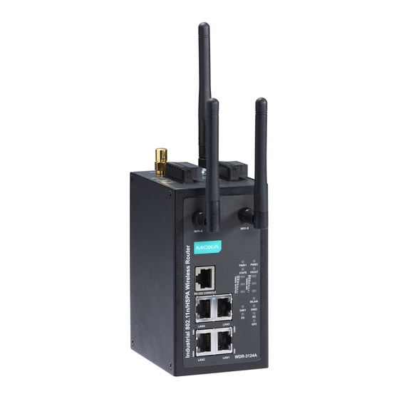
Page 4: Hardware Overview
Hardware Overview 1. GPS antenna connector (female SMA) 2. Cellular antenna connector (female SMA) 3. Grounding screw (M5) 4. Terminal block (two digital input and one digital relay) 5. Terminal block (PWR1 and PWR2) 6. WIFI antenna ports (female RP-SMA) 7. -
Page 5: Device Dimensions
Device Dimensions DIN-Rail Mounting DIN-Rail Kit Dimensions: Unit = mm (inch) The DIN-rail kit is attached to the back panel of the WDR-3124A. Mount the WDR-3124A on corrosion-free mounting rails that meet the EN 60715 standard. - 5 -... -
Page 6: Installation
Installation STEP 1: Insert the upper lip of the DIN rail into the DIN-rail mounting kit. STEP 2: Press the WDR-3124A towards the DIN rail until it snaps into place. Removal STEP 1: Pull down the latch on the mounting kit using a screwdriver. - Page 7 STEP 2: Mounting the WDR-3124A to a wall requires 4 screws. Use the WDR-3124A device, with wall mount plates attached as a guide, to mark the correct locations of the 4 screws. The heads of the screws should be less than 6.0 mm in diameter, and the shafts should be less...
-
Page 8: Wiring Requirements
Wiring Requirements WARNING Safety First! Be sure to disconnect the power cord before installing and/or wiring your WDR-3124A. WARNING Safety First! Calculate the maximum possible current in each power wire and common wire. Observe all electrical codes dictating the maximum current allowed for each wire size. If the current goes above the maximum ratings, the wiring could overheat, causing serious damage to your equipment. -
Page 9: Wiring The Redundant Power Inputs
Wiring the Redundant Power Inputs The top two pairs of contacts of the 10-contact terminal block connector on the WDR-3124A’s top panel are used for the WDR-3124A’s two DC inputs. Top and front views of the terminal block connector are shown here. -
Page 10: Communication Connections
The WDR-3124A has one RS-232 (8-pin RJ45) console port located on the front panel. Use either an RJ45-to-DB9 or RJ45-to-DB25 cable to connect the WDR-3124A’s console port to your PC’s COM port. You may then use a console terminal program to access the WDR-3124A for console configuration. -
Page 11: Led Indicators
LED Indicators The front panel of the WDR-3124A contains several LED indicators. The function of each LED is described in the table below. Color State Description Front Panel LED Indicators (System) Power is being supplied from power input 1 PWR1... -
Page 12: Specifications
Specifications Cellular Interface Standards GSM/GPRS/EDGE/UMTS/HSPA Band Options WDR-3124A-EU/US: Five band UMTS/HSPA 800/850/900/1900/2100 MHz WDR-3124A-EU/US: Quad-band GSM/GPRS/EDGE 850/900/1800/1900 MHz HSPA Data Rate Downlink: Up to 14.4 Mbps Uplink: Up to 5.76 Mbps (category 6, 7) GPRS Data Rate Downlink/Uplink: 236 kbps (class 12) - Page 13 Operating Channels WDR-3124A-EU: (central frequency) - 2.412 to 2.472 GHz (13 channels) - 5.180 to 5.240 (4 channels) WDR-3124A-US: - 2.412 to 2.462 GHz (11 channels) - 5.180 to 5.240 (4 channels) - 5.745 to 5.825 GHz (5 channels) Security...
- Page 14 RX Sensitivity 2.4GHz 802.11b: - -92 dBm @ 1 Mbps - -90 dBm @ 2 Mbps - -88 dBm @ 5.5 Mbps - -84 dBm @ 11 Mbps 802.11g: - -87 dBm @ 6 Mbps - -86 dBm @ 9 Mbps - -85 dBm @ 12 Mbps - -82 dBm @ 18 Mbps - -80 dBm @ 24 Mbps...
- Page 15 Details See www.moxa.com/support/warranty.aspx ATTENTION The WDR-3124A is NOT a portable mobile device and should be located at least 20 cm away from the human body. The WDR-3124A is NOT designed for the general public. To deploy WDR-3124A units and establish a wireless network safely, a well-trained technician should do the installation.
- Page 16 ATTENTION Use the antennas correctly: Wide-band (2G/3G) antennas are needed for the WDR-3124A to operate in a cellular network. The 2.4 GHz antennas are needed when the WDR-3124A operates in IEEE 802.11b/g/n. The 5 GHz antennas are needed for IEEE802.11a/n. Make sure that your antenna installation is within a safety area, which is covered by a lightning protection or surge arrest system.
Need help?
Do you have a question about the WDR-3124A and is the answer not in the manual?
Questions and answers