
Related Manuals for ProMinent Ammonia


Summary of Contents for ProMinent Ammonia
- Page 1 Ammonia Analyzer Operating Manual ProMinent Fluid Controls, Inc. 136 Industrial Drive│Pittsburgh, PA 15275 Phone 412-787-2484│Fax 412-787-0704 www.prominent.us...
-
Page 2: Table Of Contents
B.7 Data Logging C. START-UP D. ANALYZER OPERATION 1. Day-to-Day Operation Main Menu: Sensors, Pumps, Solenoids & Valves Checking & Clearing Alarms 2. Sensors: Ammonia (NH3), pH, temperature, 4-20mA… Sensors Sensor Calibration Sensor Alarms Sensor Configure Sensor Compensation Sensor Diagnostics 3 Flowswitches &... - Page 3 AMMONIA User Manual 5.1 Passwords 5.2 Time & Date 5.3 Keypress-Alarm Log 5.4 Enabling Inputs & Outputs 5.5 Metric & U.S. Units 5.6 Configurations 5.7 Communications 5.8 System Diagnostic 6. Product Support Application and Technical Support Specifications E. APPENDIX A. Isometric Drawing B.
-
Page 4: Theory Of Operation
) is a poisonous and pungent-smelling colorless gas that makes the eyes water. Ammonia is readily soluble in water. The aqueous solution has an alkaline reaction and is known as ammonia water or tincture of ammonia. In conjunction with acid, ammonia forms salts that disassociate in water, to form ammonium ions (NH and the corresponding anions. - Page 5 AMMONIA User Manual Some typical applications using ammonia sensors are: - municipal water plant chloramination monitoring - wastewater of gas scrubbers - wastewater monitoring - ammonia leaks in cooling towers - the food sector, e. g. for wine and beer - laboratories. The measurement can be made directly in the liquid medium. This means that it is not necessary to carry out time- consuming and complicated sample preparation. Colored or cloudy samples can also be measured. The pH value must be greater than 7.3 or the chemical equilibrium of the ammonium ions shifts towards the ammonia state. If the sample contains substances that could damage the sensor membrane, such as oils, fats or tensides, then the ammonia can still be measured, using the technique known as “head space”. In this case, damage to the sensor is ruled out, because there is no direct contact between the sensor and the sample. Measurement is performed in a gas-tight space above the substance being measured. This gas-tight space above the substance being measured is in equilibrium with the liquid as far as ammonia is concerned. The simple sample preparation makes determination of the ammonia concentration a fast and economical operation that can be applied with high precision over a wide range of concentration. Principles of analyzer operation The ammonia sensor consists of a glass pH electrode and a reference electrode which are surrounded by a common electrolyte that is separated from the liquid being measured by a hydrophobic, gas-permeable membrane. A thin layer of electrolyte is between the hydrophobic membrane and the glass pH electrode. Its pH value increases when NH gas makes its way through the membrane. The chemical processes in the electrolyte layer are described by the following reaction equation. NH3 + H2O à NH4 + OH (1) This means that NH functions as a base and thus increases the pH in the thin electrolyte layer in front of the glass pH electrode. Since there is only a very small volume of liquid between the hydrophobic PTFE membrane and the...
- Page 6 AMMONIA User Manual The electrolyte has a relatively high concentration of ammonium chloride, so the concentration of ammonium ions in the thin electrolyte layer may be regarded as constant if a small amount of NH permeates the membrane and is formed in accordance with the equation given above. As a result, the concentration of ammonium ions can be included in the equilibrium constant K´. K´ = [OH ] / [NH3] ] ~ [NH3] or (3) Applying the Nernst equation thus results in the following dependency: E = E - S log [NH3] (4) E = electrode potential = standard electrode potential S = slope, f (T) pH dependence In accordance with the above-mentioned reaction equation (Equation 1), ammonia (NH ) in an aqueous solution is in a pH-dependent equilibrium with ammonium ions (NH ). This dependence is shown in Figure 3. Fig. 3: pH dependence of the equilibrium between ammonia and ammonium ions AMMONIA_User 9/09...
- Page 7 AMMONIA User Manual Only NH ions (ammonium) are present at pH <7 The ratio of NH ions (ammonium) to NH (ammonia) is 1:1 at pH 9.3 Only NH (ammonia) is present at pH >11 If ammonium ions are predominant in the solution, as is the case in the acidic range, then they must be converted into ammonia (NH ) by the addition of a strong alkali (e. g. NaOH, adding 10 N NaOH solution to the liquid being > measured for a pH 11), since the membrane is only permeable for ammonia (water in a liquid aggregate or ionic constituents such as ammonium ions cannot pass through the membrane). Ammonia sensor membrane caps The advantage of the ProMinent sensor for ammonia is that prefabricated membrane caps are available, thus avoiding the manual fitting under tension of the sensitive membrane. Concentration range The potentiometric measurement of ammonia shows a linear characteristic over a wide range of concentration on a semi-logarithmic plot, as is indicated in the following conversion table for various units of concentration. mol/l ppm as N ppm as NH 5 x 10 7 x 10 8.5 x 10 1.4 x 10 1.7 x 10 … … … 1400 1700...
- Page 8 AMMONIA User Manual The characteristic curve that is stored in the transmitter is, of course, valid for certain specified conditions, such as the composition of the liquid and the pH value, and individual sensor characteristics also play a part. If conditions differ from those specified, or different electrodes are used, then this will affect the displayed value for the concentration. The individual characteristics of the particular sensor are allowed for in the zero point calibration. First of all, the sensor voltage is measured in the presence of ammonia, and the curve shown in Figure 5. is shifted accordingly. The slope is calculated according to the Nernst equation. This requires an automatic temperature measurement with a Pt 100 sensor. Special aspects Coloration or opacity of the liquid being measured does not affect the measurement. Most ionic substances in the sample will also have no effect, since they cannot pass through the hydrophobic membrane. But volatile amines, for instance, may affect measurement. These include various substances, e. g. methylamine, ethylamine and hydrazine. Such substances also exhibit an alkaline reaction in the sensor electrolyte. The presence of such substances in addition to ammonia leads to an erroneously high concentration reading. If the liquid being measured contains solvents or tensides from cleaning agents or detergents that can affect the hydrophobic properties of the membrane, then measurements should be made in a gas space above the liquid. This “head space” method requires that the ammonia sensor is built into a completely gas-tight fitting. A head space measurement is also advisable if oil or grease is present, since these would also block the membrane and thus adversely affect the response time of the electrode. The sensor membrane is very delicate and must not be touched in any circumstances. Cleaning by mechanical means is not possible. Measurements cannot be performed under pressure, because the compression of the inevitable air bubbles in the sensor electrolyte can cause distortion and damage to the inelastic membrane. AMMONIA_User 9/09...
-
Page 9: Installation & Navigation
B. INSTALLATION & NAVIGATION Panel is intended for wall mounting at a height where the analyzer can be easily viewed. B.1 Plumbing Inlet fitting is 3/8” hose barb and outlet connection and sample vents are 1/2” compression tubing. The inlet source should be a representative sample from the process with the following criteria: Sample flow rate: Adjust needle valve to permit enough flow to allow flow switch to... -
Page 10: Cabling-Wiring
AMMONIA User Manual B.2 Cabling – Wiring B.2.1 Analyzer Wiring Terminals Controllers consist of two circuit boards, a front Measure circuit board and a back Power board. The front, Measure circuit board supports 7 sensor inputs & 8 digital Inputs. - Page 11 AMMONIA User Manual B.2.1 Analyzer Wiring Terminals cont. The back, Power circuit board has 5 ON/OFF Power Relays, 4 Variable Frequency Feed outputs and the controller power supply The Ai, industrial version of the Aegis, includes an enclosure door mounted AC Power ON/OFF...
- Page 12 AMMONIA User Manual B.2.2 Wiring Rules Analog Sensor Wiring Analog sensors, contact sets, water meters and flowswitches may be cabled in a common conduit without causing operational problems. Do not mix AC Line, 120VAC & 240VAC wiring with any sensor or communications cable in a common conduit.
-
Page 13: Water Meters - Flowswitches - Contacts
AMMONIA User Manual B.3 Water Meters – Flowswitches – Contact Sets Water meters, flowswitches and ‘dry’ contact sets are connected to input terminals ‘O’ through ‘V’ and a ground terminal. 5VDC limited by 10K puts 1/2mA through a closed contact set. -
Page 14: Safety & Navigation
Unplug or turn OFF the AC power to the Analyzer if you have any concerns regarding safety or incorrect Analyzer operation and notify supervisory staff. YOUR ANALYZER Ammonia Analyzers are supplied in many different configurations, part numbers and sensor sets. Applications extend beyond water treatment. HELP section depicts the installation plumbing header showing the sensor set supplied with your Analyzer. - Page 15 AMMONIA User Manual N AV I G AT I O N & DOWN to view options KEYPAD or to EDIT numbers If you get lost in a sub-menu, press EXIT & you’ll Move RIGHT to select next stop what you’re doing & move back to the main...
-
Page 16: Browser
AMMONIA User Manual B.5 Browser Analyzers with the ‘LB’ LAN-Browser option include a built-in command & control web server with real time views of your Analyzer operation. You can browse with Mozilla’s Firefox or Internet Explorer 7 over a 10BaseT Ethernet connection or the internal modem, if installed. -
Page 17: Communications
3. Upload of the current controller configuration from the analyzer to support generation of View- Configuration Sets and for controller cloning. Configuration-View sets: Controllers with the ‘LB’ Ethernet option are loaded with the ammonia view. It is selected when the controller is manufactured to be the ‘as shipped’ view-configuration. LAN TCP-IP: The LB analyzer option adds a 10 Base T, RJ45 Ethernet port with a user assigned static IP. -
Page 18: Start-Up
AMMONIA User Manual C. MINIMAL START GUIDE Safety: Sensors are installed into pressurized piping. Loose or improperly assembled fittings may leak water or chemicals. Do not leave the analyzer turned ON unless you have configured it for the site’s water treatment program & verified that auxiliary equipment is operating. - Page 19 ‘G’ Temperature_G display & check that it’s displaying the approximate temperature, +/-10F. FYI: Temperature needs to be accurate. We’re using it to compensate ammonia, so it has to track, changing when the sample water changes temperature. Calibrate pH: 5...
- Page 20 Set pH Alarms: 8 Scroll DOWN to the sensor ‘C’ pH Sensor_C display ENTER Alarms and adjust both High Alarm Alarm. Set ammonia alarms: 9 Scroll DOWN to the sensor ‘D’ NH3 Sensor_D display ENTER Alarms and adjust both High Alarm Alarm.
-
Page 21: Day-To-Day Operation
AMMONIA User Manual 1.0 Day-to-Day Operation 1.1 Main Menu This is the power-on day of week & time display. Thu 16:54:10 The Serial Number tracks special features & S/N: A076X0486 the sensor set installed in your Analyzer. Press ENTER to view-set system settings Active alarms are displayed by the letter, A..Z, of the input... - Page 22 AMMONIA User Manual Users may use the Analyzer to key in results of chemical tests. These results may be used to alarm, The result of a drop test is entered, logged and displayed on control input ‘J’ Total Ammonia 0.0 ppm Input ‘S’...
-
Page 23: Checking & Clearing Alarms
AMMONIA User Manual 1.2 Checking & Clearing Alarms Thu 16:54:10 DOWN from the power ON display to view alarms. S/N: A076X0486 In this example, the sensor connected to input ‘B’ and the device controlled by Relay ‘2’ have alarmed Alarms... -
Page 24: Sensors: Ammonia (Nh3), Ph, Temperature, 4-20Ma
AMMONIA User Manual 2.0 Sensors: Ammonia, pH, Temperature, 4-20mA… 2.1 Sensors 4-20mA Inputs: Specialized sensors for other process and water treatment parameters are connected to the Analyzer 4-20mA inputs where they are used for monitoring and data logging. Sensor Operating Issues / Notes... -
Page 25: Sensor Calibration
AMMONIA User Manual 2.2 Sensor Calibration General advice on performing ammonia sensor calibration Possible calibration procedures for the potentiometric measurement of ammonia are: direct calibration with a series of calibration solutions, or the addition method. For the latter method, a known quantity of a standard solution is added to a sample of the liquid with the unknown concentration, and from the change in signal one can work back to calculate the initial concentration. During calibration and measurement, care must be taken that the sample and the calibration solution have the same temperature, otherwise the transport of water vapor through the membrane can cause drifting of the electrode. Furthermore, the temperature also affects the slope of the sensor characteristic (which is temperature-dependent in accordance with the Nernst equation). Basically, the ammonia sensor can be used over the temperature range 0 to 50°C. Ammonium chloride is recommended for making up calibration solutions. A strong alkali is used to adjust the > pH of the calibration solutions to pH 11. The sample solutions are prepared in the same way. For standard on-line operation the preparation of ppm standards for a two point calibration differing by at least a factor of 10 is described in appendix E. Sensor calibration The sensor is, of course, also suitable for measurement in situations where the user needs to determine the ammonia concentration as accurately as possible. In this case, more complex means are required for the calibration, in order to account for the various influences on the measurement. There are two ways of making a quantitative measurement of ammonia: • direct measurement, with a multi-point calibration • the standard addition method. The first method requires the setting up of a calibration curve, using reference solutions with known ammonia concentration levels. The concentration levels of the reference solutions should cover the expected concentration range of the samples. The calibration solutions and sample solutions must be treated in the same way: in order to achieve maximum measurement accuracy, the chemical equilibrium between the ammonium ions and the ammonia must be shifted towards ammonia. - Page 26 AMMONIA User Manual With the standard addition method, a known amount of ammonia (in the form of ammonium chloride) is added to the sample with the unknown concentration. From the increase in the signal after this augmentation, one can work back to derive the unknown initial concentration, whereby the increased volume of the total augmented solution must be taken into account in the calculation. With the standard addition method, the user can exclude matrix- specific influences that are not accounted for when setting up a calibration curve (the first method). The remarks made previously about the shift of the chemical equilibrium in the ammonia direction also apply to the standard addition method. Procedure for laboratory measurements In order to ensure that the chemical equilibrium between ammonium ions and ammonia is shifted towards ammonia as completely as possible, alkali must be added to the samples with the unknown concentration and the standard solutions just before starting measurement. One can, for instance, proceed as follows: 100ml of standard solution resp. 100ml of the sample have 1ml 10- mol caustic soda added until the pH value has reached at least 11 (samples with a low pH may require the addition of a substantial amount of caustic soda to reach a pH of at least 11. If in doubt, the pH must be measured). Samples and standard solution should be stirred with a magnetic mixer and mixer paddle, so that the measurement stabilizes quickly. But care must be taken that the samples and standard solutions are not warmed up by action of the magnetic mixer. If necessary, a thermally insulating plate must be placed between the vessel and the mixer plate. The ammonia sensor should be mounted on a stand in such a way that it is immersed in the liquid in the sample vessel placed on the mixer, but does not touch the magnetic mixer paddle or the bottom of the vessel. Any air bubbles on the membrane must be removed. AMMONIA_User 9/09...
- Page 27 Sidebar: Single Point and Two Point Sensor Calibration: The pH, temperature, and Ammonia sensors should be initially calibrated using two points. For example, the pH should be calibrated using standard pH buffer solutions of 7 and 10 for the low and high points, respectively. The Analyzer supports direct sets of sensor OFFSET &...
- Page 28 AMMONIA User Manual 2.2 Sensor Calibration Calibrate Faults If the Analyzer cannot calibrate you’ll view this warning after you modify the sensor value & key ENTER. Sensor Fault Ignore warning ENTER to ignore the warning or EXIT to return the sensor to its pre-calibration value.
-
Page 29: Sensor Alarms
AMMONIA User Manual 2.3 Sensor Alarms Alarms To view or adjust sensor alarm, key DOWN 1.30 ppm to the target sensor and press ENTER. Alarms ENTER @ Alarms. Configure In this example, the Analyzer will alarm if the High Alarm NH3 exceeds 1.60 ppm... - Page 30 AMMONIA User Manual 2.3 Sensor Alarms Adjust Alarms To adjust a sensor alarm, key DOWN to the target sensor and press ENTER. 1.30 ppm Alarms ENTER @ Alarms. Configure DOWN to select High Alarm, Low Alarm High Alarm Delay on Alarm &...
-
Page 31: Sensor Configure
AMMONIA User Manual 2.4 Sensor Configure Configure To view or modify sensor configuration, key DOWN to the target sensor and press ENTER. 7.46 pH Configure DOWN ENTER @ Configure. Diagnostic DOWN to view current configuration. Sensor Description may be up to 14 characters & numbers... - Page 32 AMMONIA User Manual 2.4 Sensor Configure Edit Description To modify sensor Description, key DOWN to the target sensor and press ENTER. 1.30 ppm Configure DOWN ENTER @ Configure. Diagnostic ENTER to view Description. Description Sensor Description may be up to 14 characters & numbers...
- Page 33 AMMONIA User Manual 2.4 Sensor Configure Adjust Resolution To modify sensor Resolution, the number of digital after the decimal, 1.30 ppm DOWN to the target sensor and press ENTER. Configure Diagnostic DOWN ENTER @ Configure. Decimal digits DOWN to view Decimal digits.
- Page 34 AMMONIA User Manual 2.4 Sensor Configure Disabling Sensors Disable a sensor, key DOWN to the target sensor and press ENTER. Configure Diagnostic DOWN ENTER @ Configure. Disable Input DOWN to view Disable Input. Press ENTER to Disable. The Analyzer removes the sensor from the...
-
Page 35: Sensor Compensation
AMMONIA User Manual 2.5 Sensor Compensation Some sensor compensation, like thermal compensation is user selectable. Other types of compensation are set by the sensor driver card, like corrosion rate. Each sensor type has its own set of compensations. Sensor Compensation... - Page 36 AMMONIA User Manual Thermal Compensation To view of modify sensor Compensation, 1.30 ppm DOWN to the target sensor and press ENTER. Configure DOWN ENTER @ Configure. Diagnostic Compensation None DOWN to view Compensation. Displays current Compensation type; None in this example.
-
Page 37: Sensor Diagnostics
AMMONIA User Manual 2.6 Sensor Diagnostics Diagnostic To view sensor Diagnostics, DOWN to the target sensor 1.30 ppm and press ENTER. Diagnostic ENTER @ Diagnostic. Calibrate Sensor Type; in this example. Sensor Type Also displays pH, Temperature, unused, or 4-20mA Input... - Page 38 74.6 mV Sidebar: Gain & Default Gain When you calibrate an ammonia sensor, the Analyzer adjusts the GAIN to make your measured value match the displayed value. Offset & Default Offset When you calibrate a pH, ammonia, or temperature sensor, the Analyzer adjusts the OFFSET to make your measured value match the displayed value.
-
Page 39: Flowswitches & Contact Sets
AMMONIA User Manual 3.0 Flowswitches & Contact Sets 3.1 Contact Sets Flowswitch: Provides a set of contacts that close when there is flow past or through the sensor. Flowswitch contact sets are used to permit the sensor measurement. Contact Set... -
Page 40: Contact Set Alarms
AMMONIA User Manual 3.2 Contact Set Alarms Alarms Flowswitch To view or modify contact set Alarms DOWN to the target contact set input 52.6min and press ENTER. Alarms ENTER @ Alarms. Configure Alarms if the contact set is today for... -
Page 41: Inverting Contact Sets
AMMONIA User Manual 3.3 Inverting Contact Sets A contact set can be switched Invert sense using Invert Sense. RUN/STOP To view or modify a contact set Invert Sense DOWN to the target contact set and press ENTER then DOWN. Configure... -
Page 42: Contact Set Controls
AMMONIA User Manual 3.4 Contact Set Controls In this example the Solenoid 1 Adjust Setpoints is powered by relay 4. Solenoid 1 Relay is controlled by Pressure switch ‘V’ To view or modify the Solenoid 1 setpoints DOWN Solenoid 1 and press ENTER. -
Page 43: 20Ma Outputs
AMMONIA User Manual 4.0 4-20mA Outputs 4-20mA Output Setpoints 4-20mA Outputs display both the loop Manual Setpoint current and its corresponding the 0-100%. 4-20mAOutput_D This example display occurs on installing a 4.00mA 0.0% new 4-20mA output card. To view or modify a current output... - Page 44 AMMONIA User Manual 4-20mA Output Setpoints In this example an ammonia sensor Sensor Setpoint is controlling the 4-20mA out current. 4-20mAOutput_D 100.0% indicates that the ammonia 20.00mA 100.0% is greater than the 20mA setpoint To view or modify the 20mA Setpoint press ENTER.
- Page 45 AMMONIA User Manual 4-20mA Configuration Select Sensor 4-20mAOutput_D To view or modify the sensor controlling the 4.00mA 0.0% 4-20mA output current, key DOWN to the target 4-20mA output and press ENTER. Configure ENTER @ Configure. Setpoints We’re presently in Manual mode.
- Page 46 AMMONIA User Manual 4-20mA Configuration Calibrate - Interlock To calibrate, view or modify 4-20mAOutput_D a 4-20mA output 4.00mA 0.0% DOWN to the target output and press ENTER then UP. Configure ENTER @ Configure. Setpoints The 4-20mA current output is in...
-
Page 47: System Settings
AMMONIA User Manual 5.0 System Settings 5.1 Passwords Analyzers are defaulted to Keypad Password OFF. Turn ON Passwords Thu 16:54:10 To turn ON the Keypad Password S/N: A076X0486 press ENTER DOWN Configure at the power up or day-time display. then... - Page 48 AMMONIA User Manual 5.1 Passwords After you’ve turned ON passwords and Modify Password logged in as one of the eight users: Thu 16:54:10 S/N: A076X0486 To modify your Keypad Password press ENTER Passwords then at the power up or day-time display.
- Page 49 AMMONIA User Manual 5.2 Time & Date Time & Date To view or adjust the Time&Date Thu 16:54:10 press ENTER DOWN Time&Date at the power up or day-time display. S/N: A076X0486 then Time&Date ENTER @ Time&Date. Enable I/O Analyzer Response to a new Time&Date:...
-
Page 50: Keypress-Alarm Log
AMMONIA User Manual 5.3 Keypress-Alarm Log View Activity Log To view the Activity Log Alarms press ENTER DOWN Activity Log at the Alarms display. Activity Log ENTER Activity Log. Clear Alarms Each entry in the log initially displays it’s activity as you key... -
Page 51: Enabling Inputs & Outputs
AMMONIA User Manual 5.4 Enabling Inputs & Outputs Enable I/O Enable I/O press Thu 16:54:10 ENTER DOWN Enable I/O at the power up or day-time display.. S/N: A076X0486 then Enable I/O ENTER Enable I/O. Passwords Displays the number of sensor inputs and Enable Inputs meter-contact input available for enabling. - Page 52 AMMONIA User Manual 5.4 Enabling Inputs & Outputs Enable an Input Thu 16:54:10 To enable a sensor, or contact set input press ENTER DOWN Enable I/O S/N: A076X0486 at the power up or day-time display.. then Enable I/O ENTER Enable I/O.
-
Page 53: Metric & U.s. Units
Liters and not gallons. Metric Outputs: Volumes are reported in mL & Liters. Event volumes are in Liters and not Gallons. The Analyzer uses the units of the ammonia sensor for setpoints. AMMONIA_User 9/09... -
Page 54: Configurations
Time&Date Requires ‘LB’ Option Load Factory configures the Analyzer to one of the 1 to 15 configurations shipped with the Analyzer. This Analyzer is currently running the AMMONIA Load Factory configuration. XXXXXX . View and select an alternative Analyzer configuration by keying ENTER. -
Page 55: Communications
AMMONIA User Manual 5.7 Communications This display sequence is only applicable to Communicate Analyzers with the ‘LB’, LAN-Browser option. Thu 16:54:10 See appendix LB To view or adjust the Analyzer Ethernet setting S/N: A076X486 press ENTER DOWN Communicate then at the power up or day-time display. - Page 56 AMMONIA User Manual 5.7 Communications This display sequence is only applicable to Modify IP Address Analyzers with the ‘LB’, LAN-Browser option. Thu 16:54:10 To view or adjust the Ethernet IP Address S/N: A076X486 press ENTER DOWN Communicate then at the power up or day-time display.
-
Page 57: System Diagnostic
AMMONIA User Manual 5.8 System Diagnostic To view the Analyzer’s Diagnostic Thu 16:54:10 press ENTER at the power up S/N: A076X0486 or day-time display ENTER @ Diagnostic. Diagnostic Communicate Relay Fuse Displays the state of the Relay 1 to Relay 5 AC power fuse. -
Page 58: Product Support
136 Industry Drive Pittsburgh, PA 15275 412.787.2484 Ammonia Analyzers are supplied in a many configurations; some with specialized controls. The Analyzer Serial Number and Part number available on the top, center of the Analyzer circuit board, helps us to help you. -
Page 59: Specifications
AMMONIA User Manual 6.2 Specifications Analog – Digital I/O Rating - Detail Notes Analog Inputs 3 Analog Sensors of which 3 are Analyzer auto-configures on fixed, C: pH D: NH3; & G: A...G Driver card installation and Temperature removal. Socketed for two single or dual... - Page 60 AMMONIA User Manual 6.2 Specifications Communications Rating - Detail Notes User Interface Keypad - LCD 5 Key Tactile feedback: UP / Scan rate 100mS nominal DOWN / ENTER / EXIT / RIGHT User adjustable contrast 2 Line x 16 Character, Backlit Data log download.
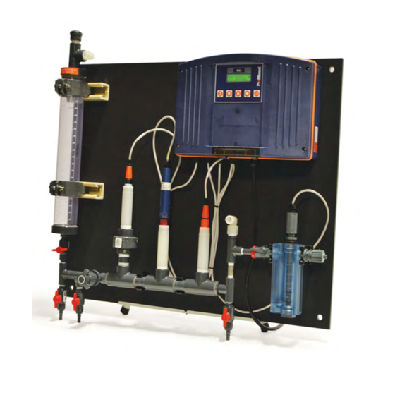
- Page 61 AMMONIA User Manual Ammonia Analyzer Assembly...
-
Page 62: Dimensions
AMMONIA User Manual APPENDIX B Ammonia Analyzer Dimensions... - Page 63 3/4"PVC tee SxSxS sch 80 703885 connector pg9 black (7735074.2) 7500067 pg9 nut Jumo sensor membrane cap* Jumo electrolyte* 1 Bottle ammonia standard 1,000 ppm* 1 pipette with bulb 1028807 1000 ml calibration column 7760254 Dual 4-20 mA output board 7760256...
-
Page 64: Component Description
4 – Sample inlet with isolation valve. 5- Metering valve to set flow rate between 200ml -500ml/min. 6- Ammonia sensor with impedance converter. (Impedance converter not shown) 7- Pt-100 temperature sensor with transducer. 8- pH sensor 9- solution grounding screw 10- overflow tube connection-tube needs to be run higher than the top of the calibration coulomb. -
Page 65: Standards Preparation For Calibration
100 ml graduated measuring flask partially filled with ammonia free distilled water, mix slightly, and then fill up to the 100 ml mark with ammonia free distilled water. This is a 100.0 ppm NH solution standard which can be used to prepare the actual calibration standards. - Page 66 Close both bottom valves and fill column approximately 250 ml with ammonia free distilled water. Add appropriate amount of the stock 100 ppm ammonia solution through the top of the calibration column based upon the concentration of the standard desired: •...
- Page 67 3. OP driver must be installed in the slot indicated below. 4. Connect the ammonia and pH sensors to the driver field wiring terminals. 5. Turn ON the analyzer after installing the OP Driver and the controller will auto-configure, displaying the installed sensor or sensors on the LCD display and browser.
-
Page 68: Driver Cards
Warning 2: Turn OFF the controller before connecting or disconnecting pH and ammonia sensors. Sensor Inputs The controller uses the letters ‘A’ thru ‘Z’ to identify sensor, water meter, flowswitch and contact set inputs and the numbers 1 to 9 to identify AC power switching relays and frequency outputs. - Page 69 2. OP driver cards can only be installed in the Sensor ‘C’ & ‘D’ slot. 3. Connect the pH and ammonia sensors to the driver field wiring terminals. 4. Turn ON the analyzer after installing the OP Driver and the controller will auto-configure, displaying the installed sensor or sensors on the LCD display and browser.
- Page 70 Warning 1: Do not install pH sensors without installing and connecting a solution ground. Unstable, drifting pHs will occur if the solution ground is disconnected. Warning 2: Turn OFF the controller before connecting or disconnecting pH and ammonia sensors. AMMONIA_User 9/09...
- Page 71 AMMONIA User Manual Sensor Set Selection Turn controller OFF before changing sensor selection jumpers. Controllers check selection jumpers on power up, loading default 1+ 1- 2+ 2- Offset and Gain on range change. Part: OP Dual pH or Dual ORP or pH &...
- Page 72 AMMONIA User Manual IO: 4-20mA Output Safety 30 VDC maximum on field wiring terminals. 24 VDC maximum on internal card surfaces. Services The IO driver provides one or two, DC isolated, loop powered 4-20mA outputs. The current output level 0% to 100% is logged by the analyzer.
- Page 73 AMMONIA User Manual Configuration - Operation Manual - Auto A 4-20mA output may be switched from Auto control to Manual. Manual mode allows the user to set an output from 0% to 100% to base feed, set up feed rates and verify monitoring inputs.
Need help?
Do you have a question about the Ammonia and is the answer not in the manual?
Questions and answers