Table of Contents
Advertisement
Quick Links
Documentation Center
RAK19010 Quick Start Guide
This guide introduces the RAK19010 WisBlock Base Board with Power Slot and how to use it.
Prerequisite
What Do You Need?
Before going through each and every step on using the WisBlock Base Board with Power Slot, make sure to
prepare the necessary items listed below:
Hardware
RAK19010 WisBlock Base Board with Power Slot
Your choice of
WisBlock Power Slot Modules
Your choice of
WisBlock Core
Your choice of
WisBlock Modules
It is highly recommended to also check the dedicated Quick Start Guide that you can follow on various
WisBlock Modules. Each Quick Start Guide of these modules contains detailed steps on how to open the
example codes and upload them to the WisBlock Core.
Li-Ion/LiPo battery (optional)
Solar charger (optional)
Software
Based on the choice of the WisBlock Core, select a Development Environment:
Programming via Arduino IDE
RAKwireless BSP support for Arduino
In Arduino IDE, once you installed the BSP, the examples for WisBlock Core will be automatically included on
the list of examples.
Programming via PlatformIO IDE:
RAKwireless WisBlock modules in PlatformIO
Product Configuration
Overview
To give you a better understanding of how the WisBlock Base works, the block diagram and power supply diagram
of RAK19010 are provided in this section.
Block Diagram
The block diagram shown in Figure 1 shows the internal architecture and external interfaces of the RAK19010
WisBlock Base Board with Power Slot.
.
Advertisement
Table of Contents

Related Manuals for RAK WisBlock RAK19010


Summary of Contents for RAK WisBlock RAK19010
- Page 1 Documentation Center RAK19010 Quick Start Guide This guide introduces the RAK19010 WisBlock Base Board with Power Slot and how to use it. Prerequisite What Do You Need? Before going through each and every step on using the WisBlock Base Board with Power Slot, make sure to prepare the necessary items listed below: Hardware RAK19010 WisBlock Base Board with Power Slot...
-
Page 2: Power Supply Diagram
Documentation Center Figure 1: RAK19010 WisBlock Base Board with Power Slot block diagram The WisBlock Power Slot module provides external interfaces to the whole board. RAK19010 will not work without the Power Slot module attached to it. The MCU in the WisBlock Core module offers the I2C, UART, and SPI data buses to the sensor modules. Through these buses, the MCU can control and retrieve data from the sensors. -
Page 3: Hardware Setup
Documentation Center RAK19010 supports 3V3_S configurable supply lines to WisBlock modules like other WisBlock Base boards. This is ideal for low-power applications. 3V3_S can be controlled by the MCU to disconnect the power sensors during idle periods to save power. 3V3_S is controlled by the IO2 pin on the WisBlock Core board. Set IO2=1, 3V3_S is on. - Page 4 Documentation Center Figure 5: Fit the WisBlock Connector’s header inside of the socket 3. After the above alignment steps, the header and socket are matched but still not buckled. Figure 6: WisBlock Connector’s header matched inside of the socket 4. Apply forces evenly by pressing in parallel, then there will be a sound confirming the completion of the buckling. Figure 7: Apply forces to buckle the header to the socket 5.
- Page 5 Documentation Center 7. If after buckling, the header and socket are not in a parallel state (not fully assembled in one place), then press the even force on both sides of the long side to complete the correct buckling. Figure 10: WisBlock Connector’s header is not parallel to the socket 8.
- Page 6 Documentation Center Figure 14: Wrong way: Do not apply force in a single corner of the header Assembling a WisBlock Module WisBlock Power Slot A WisBlock Power Slot module is designed to be installed on the Power slot of the RAK19010 Base Board. As shown in Figure 15, the location is properly marked by silkscreen.
- Page 7 Documentation Center Figure 16: WisBlock Core silkscreen on the RAK19010 Base Board WisBlock IO A WisBlock IO module is designed to be installed on the IO slot of the RAK19010 Base Board. As shown in Figure 17, the location is properly marked by silkscreen. Follow carefully the procedure defined in attaching a WisBlock Connector section in order to attach an IO module.
-
Page 8: Software Setup
Documentation Center Figure 19: Removing screws from the WisBlock module 2. Once the screws are removed, on the PCB of a WisBlock module, there is a silkscreen that shows the correct location where force can be applied. By applying even force under the marked area, the module can be detached from the Base Board. - Page 9 Documentation Center WisBlock Examples Repository To quickly build your IoT device with less hassle, example codes for WisBlock Core are provided. You can access the codes on the WisBlock Example code repository . The example codes on folder are compatible common with RAK4631, RAK11200, and RAK11310 WisBlock cores.
- Page 10 Documentation Center RAK19010 WisBlock Base Board with Power Slot Datasheet Overview Description RAK19010 is a WisBlock Base Board with Power Slot that connects WisBlock Core and other WisBlock Modules. The power slot of RAK19010 is required to have an attached WisBlock Power Slot module that provides power supply to the core and other modules.
-
Page 11: Block Diagram
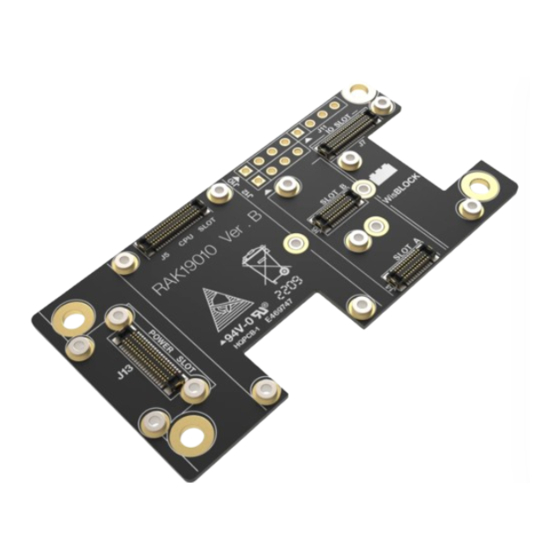
Documentation Center Environmental monitoring Wireless data transmission Data acquisition in the industrial environment Location and tracking of personnel or moving objects Specifications Overview There are seven (7) slots on RAK19010 WisBlock Base Board with Power Slot: CPU SLOT: This slot is reserved for the WisBlock Core module which has the main MCU. Power SLOT: This slot is required to provide power to WisBlock Core and modules. - Page 12 Documentation Center Figure 3: RAK19010 WisBlock Base Board wth Power Slot block diagram Hardware The hardware specification is categorized into six parts. It shows the interfacing, pinouts, and their corresponding functions and diagrams. It also presents the electrical, environmental, and mechanical parameters that include the tabular data of the functionalities and standard values of the RAK19010 WisBlock Base Board 2nd Gen.
- Page 13 Documentation Center Figure 4: RAK19010 top and bottom parts J10, J11, J12 Headers On the RAK19010 Base Board, there are three 2.54 mm pitch headers for IO extension. BOOT, I2C, GPIO, and UART pins from the WisBlock Core module are also connected to these headers. J10 Header Pinout Pin Name Description...
-
Page 14: Pin Definition
Documentation Center Pin Name Description AIN1 ADC input signal General purpose IO General purpose IO VBAT Battery voltage J12 Header Pinout Pin Name Description 3.3 V Ground pin I2C1 clock I2C2 data NOTE BOOT pin BOOT pin is used on startup configuration or sequence of the WisBlock Core connected to it. It is commonly used for uploading the bootloader and/or application firmware. - Page 15 Documentation Center Function Name of WisBlock Function Name of WisBlock Base Number Number Base VBAT VBAT USB+ USB– VBUS TXD0 RXD0 RESET LED1 LED2 LED3 I2C1_SDA I2C1_SCL AIN0 AIN1 BOOT0 SPI_CS SPI_CLK SPI_MIS0 SPI_MOSI TXD1 RXD1 I2C2_SDA I2C2_SCL As for the following table, it shows the definition of each pin of the WisBlock Core connector:...
- Page 16 Documentation Center Pin Name Type Description Number VBAT Power supply from battery VBAT Power supply from battery Ground Ground 3.3 V power supply 3.3 V power supply USB+ USB D+ USB– USB D– VBUS VBUS for USB Switch signal for customer's control TXD0 MCU UART0 TX signal RXD0...
- Page 17 Documentation Center Pin Name Type Description Number Not connected SPI_CS SPI chip select signal SPI_CLK SPI clock SPI_MISO SPI MISO signal SPI_MOSI SPI MOSI signal General purpose IO Used for 3V3_S enable General purpose IO General purpose IO TXD1 MCU UART1 RX signal RXD1 MCU UART1 RX signal I2C2_SDA...
- Page 18 Documentation Center Function Name of WisBlock Function Name of WisBlock Number Base Number Base VBAT VBAT USB+ USB– VBUS VBUS RESET LED1 LED2 I2C1_SDA I2C1_SCL AIN0 AIN1 SPI_CS SPI_CLK SPI_MISO SPI_MOSI I2C2_SDA I2C2_SCL As for the following table, it shows the definition of each pin of the WisBlock Power connector:...
- Page 19 Documentation Center Pin Number Pin Name Type Description VBAT Power supply from battery VBAT Power supply from battery Ground Ground 3.3 V power supply 3.3 V power supply USB+ USB D+ USB– USB D– VBUS USB VBUS VBUS USB VBUS Not connected Not connected RESET...
- Page 20 Documentation Center Pin Number Pin Name Type Description SPI_CS SPI chip select signal SPI_CLK SPI clock signal SPI_MISO SPI MISO signal SPI_MOSI SPI MOSI signal Not connected Not connected Not connected Not connected Not connected Not connected I2C2_SDA The second set of I2C data signal I2C2_SCL The second set of I2C clock signal General purpose IO...
- Page 21 Documentation Center Connector Connector Connector Connector Connector Number Number TXD1 TXD1 SPI_CS SPI_CS SPI_CS SPI_CS SPI_CLK SPI_MISO SPI_MISO SPI_MISO SPI_MISO SPI_MOSI I2C1_SCL I2C1_SCL I2C1_SCL I2C1_SCL I2C1_SDA 3V3_S 3V3_S 3V3_S 3V3_S 3V3_S RXD1 As for the following table, it shows the pin name and description of each pin in the WisBlock Sensor module connector.
- Page 22 Documentation Center Connector Connector Connector Connector Type Description Number TXD1 TXD1 UART TX signal Ground SPI chip select SPI_CS SPI_CS SPI_CS SPI_CS signal SPI_CLK SPI_CLK SPI_CLK SPI_CLK SPI clock SPI_MISO SPI_MISO SPI_MISO SPI_MISO SPI MISO signal SPI_MOSI SPI_MOSI SPI_MOSI SPI_MOSI SPI MOSI signal I2C1_SCL I2C1_SCL...
- Page 23 Documentation Center Connector Connector Connector Connector Type Description Number 3.3 V power supply. Can be 3V3_S 3V3_S 3V3_S 3V3_S shut down by the CPU module. Not connected Generated by CPU module. Used to power sensor board if the MCU IO level is not 3.3 V.
- Page 24 Documentation Center Connector B Connector A Pin Number Pin Number Connector A Connector B VBAT VBAT VBAT VBAT 3V3_S 3V3_S USB+ USB+ USB– USB– VBUS VBUS TXD0 TXD0 RXD0 RXD0 RESET RESET LED1 LED1 LED2 LED2 LED3 LED3 I2C1_SDA I2C1_SDA I2C1_SCL I2C1_SCL AIN0...
- Page 25 Documentation Center Pin Name Type Description Number VBAT Power supply from battery VBAT Power supply from battery Ground Ground 3.3 V power supply 3V3_S 3.3 V power supply. Can be shut down by a CPU module. USB+ USB D+ USB– USB D–...
- Page 26 Documentation Center Pin Name Type Description Number Not connect SPI_CS SPI chip select signal SP_CLK SPI clock SPI_MISO SPI MISO signal SPI_MOSI SPI MOSI signal General purpose IO Used for 3V3_S enable General purpose IO General purpose IO TXD1 MCU UART1 TX signal RXD1 MCU UART1 RX signal I2C2_SDA...
-
Page 27: Mechanical Characteristics
Documentation Center Ratings Maximum Value Unit IOs of WisConnector –0.3 to VDD+0.3 2000 ⚠ WARNING The RAK19010, like any electronic equipment, is sensitive to electrostatic discharge (ESD). Improper handling can cause permanent damage to the module. Mechanical Characteristics Board Dimensions Figure 11 shows the detailed mechanical dimensions of the RAK19010 Board. -
Page 28: Environmental Characteristics
Documentation Center WisConnector PCB Layout Figure 11: WisConnector PCB footprint and recommendations Environmental Characteristics The table below lists the operation and storage temperature requirements of RAK19010: Parameter Minimum Typical Maximum Operational temperature range –35 ºC +25 ºC +75 ºC Extended temperature range –40 ºC +25 ºC +80 ºC... - Page 29 Documentation Center Figure 12: RAK19010 schematic diagram (Power) Last Updated: 7/29/2022, 10:17:19 PM...
Need help?
Do you have a question about the WisBlock RAK19010 and is the answer not in the manual?
Questions and answers