Advertisement
Quick Links
Documentation Center
RAK3172 Module Quick Start Guide
This guide covers the following topics:
TheThingsNetwork Guide
RAK3172 TTN OTAA Guide
OTAA activation.
RAK3172 TTN ABP Guide
activation.
Chirpstack Guide
- How to create new applications on Chirpstack.
RAK3172 Chirpstack OTAA Guide
RAK3172 OTAA activation.
RAK3172 Chirpstack ABP Guide
RAK3172 ABP activation.
LoRa P2P
- Point to point communication between two RAK3172 modules.
Updating RAK3172-Module FW
Prerequisites
What Do You Need?
Before going through the steps in the installation guide of the RAK3172 WisDuo LPWAN Module, make sure to
prepare the necessary items listed below:
Hardware Tools
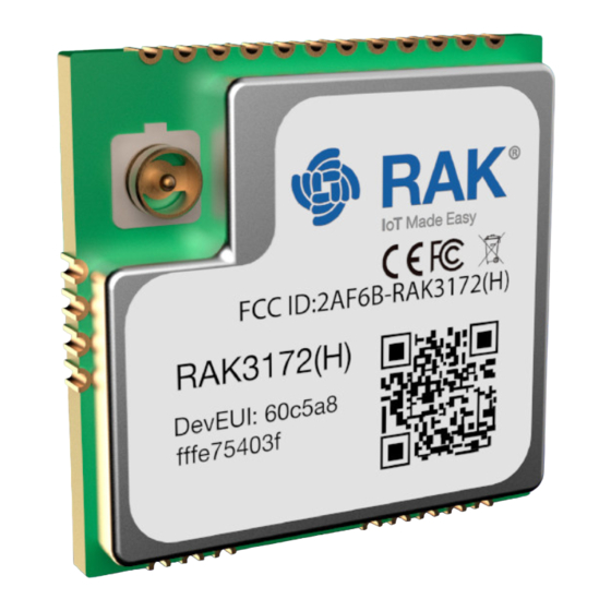
1. RAK3172 WisDuo LPWAN Module
2. Computer
3. USB to UART TTL adapter
Software Tools
1.
RAK Serial Port Tool
List of Acronyms
- How to login, register new accounts and create new applications on TTN.
- How to add OTAA device on TTN and what AT commands to use on RAK3172
- How to add ABP device on TTN and what AT commands to use on RAK3172 ABP
- How to add OTAA device to Chirpstack and what AT commands to use on
- How to add ABP device on Chirpstack and what AT commands to use on
- Procedures on how to update RAK3172 module firmware.
Advertisement

Related Manuals for RAK RAK3172


Summary of Contents for RAK RAK3172
- Page 1 - Procedures on how to update RAK3172 module firmware. Prerequisites What Do You Need? Before going through the steps in the installation guide of the RAK3172 WisDuo LPWAN Module, make sure to prepare the necessary items listed below: Hardware Tools 1.
- Page 2 AT commands and view the replies from the console output. Connect to the RAK3172 1. Connect the RAK3172 to the serial port of a general-purpose computer (USB port) using a USB to UART TTL adapter like RAKDAP1...
- Page 3 RAK3172. Connecting to The Things Network (TTN) In this section, a quick tutorial guide will show how to connect the RAK3172 module to the TTN platform. NOTE: In this guide, you need to have a working gateway that is connected to TTN or you have to be within coverage of a TTN community network.
- Page 4 The RAK3172 WisDuo module can be part of this ecosystem as a device, and the objective of this section is to demonstrate how simple it is to send data to The Things Stack using the LoRaWAN protocol. To achieve this, the RAK3172 WisDuo module must be located inside the coverage of a LoRaWAN gateway connected to The Things Stack server.
- Page 5 Documentation Center Figure 4: Login using TTN account Figure 5: Registration of new account You should now be on the step of creating your TTN account. Fill all the necessary details and activate your account. After creating an account, you should login on the platform using your username/email and password then click Submit as shown on Figure 6.
- Page 6 Documentation Center Figure 6: Logging in to TTN platform You need to click Authorize to proceed. Figure 7: Authorization to TTN Now that you are logged in to the platform, the next step is to create an application. Click Create an application.
- Page 7 Documentation Center Figure 8: Creating TTN application for your LoRaWAN devices To have an application registered, you need to input first the specific details and necessary information about your application then click Create application. Figure 9: Details of the TTN application If you had no error during the previous step, you should now be on the application console page.
- Page 8 Documentation Center Figure 10: Add end device To register the module, you need to click first Manually then configure the activation method by selecting Over the air activation (OTAA) and compatible LoRaWAN version then click Start button as shown on figures 11 and 12. Figure 11: Manually register device to TTN...
- Page 9 It is advisable to use a meaningful end-device ID, end-device name and end-device description that will match your device purpose. The end-device ID is for illustration purposes only. rak-device Figure 13: OTAA Device Information The next step is to set up the Frequency plan, a compatible Regional Parameter version and the LoRaWAN...
- Page 10 Documentation Center Figure 14: OTAA Configuration The last step in the registration of a new OTAA end-device is the configuration of the AppKey. To get the AppKey, you must click the generate button. Then you need to click Add end device to finish your new device registration.
- Page 11 To set up the RAK3172 module to join the TTN using OTAA, start by connecting the RAK3172 module to your computer (see Figure 1) and open the RAK Serial Port Tool. Select the right COM port and set the baudrate to 9600.
- Page 12 9600. Also you can check if the device is powered correctly. If you are getting power from USB port, ensure that you have a good USB cable. Figure 17: at+version command response The next step is to configure the OTAA LoRaWAN parameters in RAK3172: LoRa work mode: LoRaWAN LoRaWAN join mode: OTAA...
- Page 13 NOTE: Depending on the Regional Band you selected, you might need to configure the sub-band of your RAK3172 to match the gateway and LoRaWAN network server. This is especially important for Regional Bands like US915, AU915, and CN470. To configure the masking of channels for the sub-bands, you can use the...
- Page 14 Documentation Center Figure 18: Configuring LoRa Parameters After configuration of the LoRaWAN parameters, the next step is to set up the EUIs and key. You need the use the values from the TTN console. Device EUI: 1133557799224466 Application EUI: 1000000000000009 Application Key: 04FA4E626EF5CF227C969601176275C2 Set the Device EUI.
- Page 15 Documentation Center Figure 19: Configuring LoRa Parameters After EUI and keys configuration, the device can now join the network and send payloads. AT+JOIN=1:0:10:8 Join command format: AT+JOIN=w:x:y:z Parameter Description Join command - 1: joining, 0: stop joining. Auto-join config - 1: auto-join on powerup, 0: no auto-join Reattempt interval in seconds (7-255) - 8 is default.
- Page 16 Figure 20: OTAA Test Sample Data Sent via RAK Serial Port Tool You can see the data sent by the RAK3172 module on the TTN device console Live data section. Also, the Last seen info should be a few seconds or minutes ago.
- Page 17 Documentation Center Figure 22: Adding ABP Device To register the module, you need to click first Manually then configure the activation method by selecting Activation by personalization (ABP), compatible LoRaWAN version and click Start button as shown in figures 23 and 24. Figure 23: Manually register device to TTN...
- Page 18 After putting all the details, you need to click Network layer settings to proceed on the next step. NOTE: It is advisable to use a meaningful end-device ID, end-device name and end-device description that will match your device purpose. The end-device ID is for illustration purposes only. rak-device-abp...
- Page 19 Documentation Center Figure 25: ABP Device Information The next step is to set up the Frequency plan, a compatible Regional Parameter version and the LoRaWAN class supported. In an ABP device, you also need to generate a Device Address and a NwkSKey (Network Session Key).
- Page 20 ABP Configuration for TTN To set up the RAK3172 module to join the TTN using ABP, start by connecting the RAK3172 module to the computer (see Figure 1) and open the RAK Serial Port Tool. Select the right COM port and set baudrate to 9600.
- Page 21 9600. Also you can check if the device is powered correctly. If you are getting power from USB port, ensure that you have a good USB cable. Figure 29: at+version command response The next step is to configure the ABP LoRaWAN parameters in RAK3172: LoRa work mode: LoRaWAN LoRaWAN join mode: ABP...
- Page 22 NOTE: Depending on the Regional Band you selected, you might need to configure the sub-band of your RAK3172 to match the gateway and LoRaWAN network server. This is specially important on Regional Bands like US915, AU915, and CN470. To configure the masking of channels for the sub-bands, you can use the...
- Page 23 Documentation Center Code Regional Band AS923-3 AS923-4 Figure 30: Configuring LoRa Parameters After configuration of the LoRaWAN parameters, the next step is to setup the device address and sessions keys. You need the use the values from the TTN console. Device Address: 260BDE80 Application Session Key: A585903A949C2B2D44B55E99E94CB533 Network Session Key: 433C7A924F7F6947778FE821525F183A...
- Page 24 Documentation Center Figure 31: Configuring LoRa Parameters After EUI and keys configuration, the device can now join the network and send some payload. AT+JOIN=1:0:8:0 Join command format: AT+JOIN=w:x:y:z Parameter Description Join command - 1: joining, 0: stop joining. Auto-join config - 1: auto-join on powerup, 0: no auto-join Reattempt interval in seconds (7-255) - 8 is default.
- Page 25 Figure 32: ABP Test Sample Data Sent via RAK Serial Port Tool You can see the data sent by the RAK3172 module on the TTN device console Live data section and the Last seen info should be few seconds ago.
-
Page 26: Create A New Application
The ChirpStack, previously known as the LoRaServer project, provides open-source components for building LoRaWAN networks. Like in the case of TTN, the RAK3172 module is located in the periphery and will transmit the data to the backend servers through a LoRa gateway. Learn more about... - Page 27 Documentation Center Figure 35: Application Section By default, you should create a new application, although you can reuse existing ones. For this setup, create a new Application by clicking on the “CREATE” button, and fill the required parameters as shown in the Figures 36 and 37.
- Page 28 Documentation Center 1. Choose the Application created in the previous step, then select the DEVICES tab as shown in Figures 38 and 2. Once done, click “+ CREATE”. Figure 38: List of Applications Created Figure 39: Device Tab of an Application 3.
- Page 29 Documentation Center Figure 41: Chirpstack Adding Node into the RAK3172 Module 6. Once the node is created, fill in the necessary data. You can generate a Device EUI automatically by clicking the following icon, or you can write a correct Device EUI in the edit box.
- Page 30 Documentation Center 1. If you have selected “DeviceProfile_OTAA” as shown in Figure 43, then after the device is created, an Application Key must be also created for this device. Figure 43: Chirpstack OTAA Activation 2. A previously created Application Key can be entered here, or a new one can be generated automatically by clicking the icon highlighted in red in Figure 44: Figure 44: Chirpstack OTAA Set Application Keys 3.
- Page 31 To set up the RAK3172 module to join the Chirpstack using OTAA, start by connecting the RAK3172 module to the Computer (see Figure 1) and open the RAK Serial Port Tool. Select the right COM port and set baudrate to 9600.
- Page 32 9600. Also you can check if the device is powered correctly. If you are getting power from USB port, ensure that you have a good USB cable. Figure 47: at+version command response The next step is to configure the OTAA LoRaWAN parameters in RAK3172: LoRa work mode: LoRaWAN LoRaWAN join mode: OTAA...
- Page 33 NOTE: Depending on the Regional Band you selected, you might need to configure the sub-band of your RAK3172 to match the gateway and LoRaWAN network server. This is specially important for Regional Bands like US915, AU915, and CN470. To configure the masking of channels for the sub-bands, you can use the...
- Page 34 Documentation Center Figure 48: Configuring LoRa Parameters After configuration of the LoRaWAN parameters, the next step is to set up the DevEUI and AppKey. You need the use the values from the Chirpstack device console. NOTE: The Application EUI parameter is not required in the ChirpStack platform; therefore, it possible to use the same id as the Device EUI.
- Page 35 Documentation Center Figure 49: Configuring LoRa Parameters After EUI and key configuration, the device can now join the network and send some payload. AT+JOIN=1:0:10:8 Join command format: AT+JOIN=w:x:y:z Parameter Description Join command - 1: joining, 0: stop joining. Auto-join config - 1: auto-join on powerup, 0: no auto-join Reattempt interval in seconds (7-255) - 8 is default.
- Page 36 Send command format: AT+SEND=<port>:<payload> Figure 50: OTAA Test Sample Data Sent via RAK Serial Port Tool On the ChirpStack platform, you should see the join and uplink messages in the LORAWAN FRAMES tab as shown in Figure 51. By convention, messages sent from nodes to gateways are considered as Uplinks while messages sent by gateways to nodes are considered as Downlinks.
- Page 37 ABP Configuration for Chirpstack To set up the RAK3172 module to join the Chirpstack using ABP, start by connecting the RAK3172 module to the Computer (see Figure 1) and open the RAK Serial Port Tool. Select the right COM port and set baudrate to 9600.
- Page 38 9600. Also you can check if the device is powered correctly. If you are getting power from USB port, ensure that you have a good USB cable. Figure 54: at+version command response The next step is to configure the ABP LoRaWAN parameters in RAK3172: LoRa work mode: LoRaWAN LoRaWAN join mode: ABP...
- Page 39 NOTE: Depending on the Regional Band you selected, you might need to configure the sub-band of your RAK3172 to match the gateway and LoRaWAN network server. This is specially important on Regional Bands like US915, AU915, and CN470. To configure the masking of channels for the sub-bands, you can use the...
- Page 40 Documentation Center Code Regional Band AS923-3 AS923-4 Figure 55: Configuring LoRa Parameters After configuration of the LoRaWAN parameters, the next step is to setup the device address and session keys. You need the use the values from the TTN device console. Device Address: 26011AF9 Application Session Key: 4D42EC5CAF97F03D833CDAf5003F69E1 Network Session Key: C280CB8D1DF688BC18601A97025C5488...
- Page 41 Documentation Center Figure 56: Configuring LoRa Parameters After EUI and keys configuration, the device can now join the network and send some payload. AT+JOIN=1:0:10:8 Join command format: AT+JOIN=w:x:y:z Parameter Description Join command - 1: joining, 0: stop joining. Auto-join config - 1: auto-join on powerup, 0: no auto-join Reattempt interval in seconds (7-255) - 8 is default.
- Page 42 LoRa P2P Mode This section will show you how to set up and connect two RAK3172 units to work in the LoRa P2P mode. The configuration of the RAK3172 units are done by connecting the two modules to a general-purpose computer using a USB-UART converter.
- Page 43 Documentation Center Figure 58: at+version command response To setup the RAK3172 to work in LoRa P2P mode, you need to input the work mode command on both RAK3172 modules. AT+NWM=0 Figure 59: P2P Mode NOTE: You might need to input command again to ensure that your succeeding commands on P2P mode echo on the terminal.
- Page 44 Bandwidth: 125 kHz Coding Rate: 0 = 4/5 Preamble Length: 10 Power: 14 dBm We need to input the P2P setup on both RAK3172 modules. The parameters should be exactly the same on the two modules. AT+P2P=868000000:7:125:0:10:14 NOTE: Refer to the...
- Page 45 With one module configured as RX, the other device will be the TX. You can now try to send a P2P payload. AT+PSEND=11223344 Figure 61: Configuring P2P in both RAK3172 Module Miscellaneous Upgrading the Firmware If you want to upgrade to the latest version firmware of the module, you can follow this section. The latest firmware...
-
Page 46: Firmware Upgrade Procedure
2. Download the RAK Device Firmware Upgrade (DFU) tool. RAK Device Firmware Upgrade (DFU) Tool 3. Connect the RAK3172 module with a computer through a USB to TTL. Refer to Figure 4. Open the Device Firmware Upgrade tool. Select the serial port and baud rate (9600) of the module and click the "Select Port"... - Page 47 Documentation Center Figure 63: Select Firmware 6. Click the "Upgrade" button to upgrade the device. After the upgrade is complete, the RAK3172 module will be ready to work with the new firmware. Figure 64: Firmware Upgrading Figure 65: Upgrade Successful...
- Page 48 Documentation Center Last Updated: 1/10/2022, 2:07:11 AM...
Need help?
Do you have a question about the RAK3172 and is the answer not in the manual?
Questions and answers