Advertisement
Quick Links
Documentation Center
RAK4600 Module Quick Start Guide
This guide covers the following topics:
The Things Stack (TTN V3) OTAA Guide
RAK4600 OTAA AT Commands for The Things Stack
The Things Stack (TTN V3) ABP Guide
RAK4600 ABP AT Commands for The Things Stack
Chirpstack OTAA Guide
RAK4600 OTAA AT Commands for Chirpstack
Chirpstack ABP Guide
RAK4600 ABP AT Commands for Chirpstack
LoRa P2P Guide
Updating RAK4600 FW Procedure
Prerequisites
What Do You Need?
Before going through the step in the installation guide of the RAK4600 WisDuo LPWAN Module, make sure to
prepare the necessary items listed below:
Hardware Tools
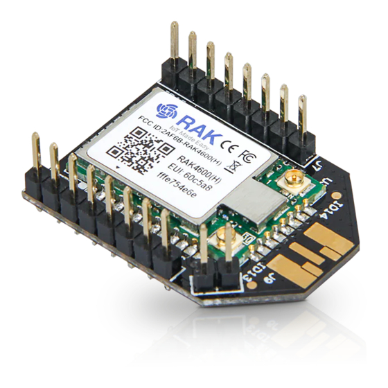
1. RAK4600 WisDuo LPWAN Module
2. Windows PC
3. USB to TTL adapter
4. RAKDAP1 Flash and Debug Tool
5. LoRaWAN gateway in range
Software Tools
1.
RAK Serial Port Tool
2.
RAK4600 Firmware
3.
RAK Firmware Upgrade Tool
Definition of Terms
List of Acronyms
Advertisement

Related Manuals for RAK RAK4600


Summary of Contents for RAK RAK4600
- Page 1 Updating RAK4600 FW Procedure Prerequisites What Do You Need? Before going through the step in the installation guide of the RAK4600 WisDuo LPWAN Module, make sure to prepare the necessary items listed below: Hardware Tools 1. RAK4600 WisDuo LPWAN Module 2.
- Page 2 Interfacing with RAK4600 In this section, a RAK4600 module is used for demonstration. Use a USB to TTL adapter to connect to the module. In case the RAK4600 module is mounted on an evaluation board or a custom PCB, use the appropriate interface to connect to the serial port.
- Page 3 Documentation Center Figure 2: RAK4600 module connection 2. Open RAK Serial Port Tool. Any serial communication tool will work, but it is recommended to use the RAK Serial Port Tool. RAK Serial Port Tool 3. Configure the serial communication tool by selecting the proper port of the computer UART port and configure the link as 115200 baud, 8 bits, no parity bit, and 1 stop bit.
- Page 4 Documentation Center 4. The RAK4600 console output can now be read in the RAK serial port tool, as shown in Figure 4. Figure 4: RAK4600 on RAK Serial Port Tool Configure the RAK4600 Through UART To connect the RAK4600 module to a LoRa P2P connection or a LoRaWAN network, the module must be configured, and the LoRa parameters must be set by sending AT commands through the UART interface.
- Page 5 1. Install the “nRF Connect” or the “nRF Master Control Panel (BLE)” app provided by Nordic Semiconductor. 2. Open the app on the mobile device and scan for BLE devices. 3. Reset the RAK4600 module. After a few seconds, a list of BLE devices will be shown. The RAK4600 is listed as “RUI-XX: XX: XX".
- Page 6 Documentation Center 4. After pressing the “CONNECT” button, a list will be displayed, as shown in Figure 7. Figure 7: Options to connect to the RAK4600 5. Select the service named “Nordic UART Service”. 6. To receive data from mobile, enable notification on TX Characteristic by clicking on the arrow.
- Page 7 8. A small input window will pop up. This is where you will input the AT commands. Figure 10: nRF app AT command input window 9. Send AT commands to RAK4600 in this dialog. For example, to check the current firmware version, type “...
- Page 8 The console output shall be read on the TX Characteristic of the App. Figure 12: AT response over BLE Connecting to The Things Stack (TTN V3) This section will show how to connect the RAK4600 module to The Things Stack (TTN V3) platform.
- Page 9 The RAK4600 module can be part of this ecosystem as a device, and the objective of this section is to demonstrate how simple it is to send data to The Things Stack using the LoRaWAN protocol. To achieve this, the RAK4600 module must be located inside the coverage of a LoRaWAN gateway connected to The Things Stack server.
- Page 10 Documentation Center 1. To register as a new user to TTN, click on Login with The Things ID, then select register on the next page, as shown in Figure 15 and Figure 16. Figure 15: Login using TTN account Figure 16: Registration of new account 2.
- Page 11 Documentation Center Figure 17: Logging in to TTN platform 4. Click Authorize to proceed. Figure 18: Authorization to TTN 5. Now that you are logged in to the platform, the next step is to create an application. Click Create an application.
- Page 12 Documentation Center Figure 19: Creating TTN application for your LoRaWAN devices 6. To have an application registered, input first the specific details and necessary information about your application, then click Create application. Figure 20: Details of the TTN application If you have no error on the previous step, you should now be on the application console page. The next step is to add end-devices to your The Things Stack application.
- Page 13 Documentation Center NOTE: Once you have the application in The Things Stack (TTN V3), you need to ensure that you are in coverage of a LoRaWAN gateway that is registered to The Things Stack (TTN V3) as well. Without the coverage of that LoRaWAN gateway, you cannot activate any device that you will register in your application.
- Page 14 4. After putting all the details, click Network layer settings to proceed to the next step. NOTE: It is advisable to use a meaningful End device ID, End device name, and End device description that will match your device purpose. The End device ID is for illustration purposes only. rak-device...
- Page 15 Documentation Center Figure 24: OTAA Device Information 5. Next step is to set up Frequency plan, compatible Regional Parameter version, and LoRaWAN class supported. Then you can click Join settings. Figure 25: OTAA Configuration 6. The last step in the registration of a new OTAA end-device is the configuration of the AppKey. To get the AppKey, you must click the generate button, then click Add end device to finish your new device registration.
- Page 16 The three OTAA parameters on The Things Stack device console are MSB by default. These parameters are always accessible on the device console page, as shown in Figure 27. Figure 27: OTAA device successfully registered to The Things Stack RAK4600 OTAA Configuration for The Things Stack...
- Page 17 To set up the RAK4600 module to join The Things Stack using OTAA, start by connecting the RAK4600 module to the computer (see Figure 1) and open the RAK Serial Port Tool. Wait for the communication to start. It is recommended to test the serial communication and verify the current configuration by...
- Page 18 Documentation Center 3. Set the frequency/region to EU868. Refer to the RAK4600 Datasheet for the list of supported frequencies. at+set_config=lora:region:EU868 4. Set the Device EUI. at+set_config=lora:dev_eui:1133557799224466 5. Set the Application EUI. NOTE: All zero value Application EUI is not supported and at+set_config=lora:app_eui:0000000000000000 will return error.
- Page 19 8. Try to send a message from the RAK4600 module. at+send=lora:2:1234567890 Figure 30: OTAA Test Sample Data Sent via RAK Serial Port Tool You can see the data sent by the RAK4600 module on The Things Stack platform, as shown in Figure 31.
- Page 20 Documentation Center Figure 31: OTAA Test Sample Data Sent Viewed in The Things Stack The Things Stack ABP Device Registration 1. To register an ABP device, go to your application console and select the application where you want your device to be added, then click + Add end device, as shown in Figure 32. Figure 32: Add end device 2.
- Page 21 4. After putting all the details, click Network layer settings to proceed to the next step. NOTE: It is advisable to use a meaningful End device ID, End device name, and End device description that will match your device purpose. The End device ID is for illustration purposes only. rak-device-abp...
- Page 22 Documentation Center Figure 35: Device Information 5. Next step is to set up Frequency plan, compatible Regional Parameter version, and LoRaWAN class supported. In an ABP device, you also need to generate Device Address and NwkSKey (Network Session Keys). Then, you can click Application layers settings. Figure 36: ABP Configuration in The Things Stack 6.
- Page 23 RAK4600 ABP Configuration for The Things Stack To set up the RAK4600 module to join The Things Stack using ABP, start by connecting the RAK4600 module to the computer (see Figure 1) and open the RAK Serial Port Tool. It is recommended to test the serial...
- Page 24 Documentation Center at+set_config=device:restart at+version Figure 39: AT Command response As an example, these are the list of the parameters you need to configure in RAK4600: LoRa join mode: ABP LoRa class: Class A LoRa region: EU868 Device address: 260BDE80 Network Session Key: 433C7A924F7F6947778FE821525F183A Application Session Key: A585653A949C2B2D44B55E99E94CB533 1.
- Page 25 6. Set the LoRa Application Session Key. at+set_config=lora:apps_key:A585653A949C2B2D44B55E99E94CB533 Figure 40: AT Command for ABP LoRa parameters via RAK Serial Port Tool After configuring all the parameters, you need to reset the RAK4600 Module to save the parameters. 7. After resetting, join in ABP mode. at+join...
- Page 26 Figure 41: ABP Test Sample Data Sent via RAK Serial Port Tool You can see the data sent by the RAK4600 module on The Things Stack device console Live data section and the Last seen info should be a few seconds ago.
- Page 27 Figure 43: RAK4600 in the context of the ChirpStack platform The architecture of the ChirpStack platform is shown in Figure 43. Similar to the case of TTN, the RAK4600 is located in the periphery and will transmit the data to the backend servers through a LoRa gateway. More information about this architecture can be found at https://www.chirpstack.io/...
- Page 28 Documentation Center In this section, it is assumed that you are using a RAK LoRa gateway, such as RAK7243. The gateway must be configured and registered previously to ChirpStack deployment. More information can be found in the Connect the Gateway with Chirpstack section.
- Page 29 Service profile: field is to select the system profile. The Application Description field is just a descriptive text. “CREATE APPLICATION”. Figure 46: Filling parameters of an Application on the RAK’s ChirpStack LoRaServer Register a new Device 4. Click on the Application “rak_node_test” created in the previous step.
- Page 30 5. Select the “DEVICES” tab, as shown in Figure 48. Figure 48: Device tab of an Application on the RAK’s ChirpStack LoRaServer 6. Inside of the “DEVICES” tab, create a new device (LoRa node) by clicking on the “+ CREATE” button.
- Page 31 Documentation Center Figure 49: Add a new device at DEVICES tab of an Application on the RAK’s ChirpStack LoRaServer Figure 50: New device registration form on the RAK’s ChirpStack LoRaServer 7. Fill the parameters requested as appears in Figure 50.
- Page 32 Documentation Center Figure 51: Generate a new Device EUI in the device registration form LoRaWAN Join Mode The LoRaWAN specification defines that to join in a LoRaWAN network, each end-device has to be personalized and activated. Activation can be done either via Over-The-Air-Activation (OTAA) or via Activation-By- Personalization (ABP).
- Page 33 Documentation Center Figure 53: Application Key for the OTAA mode in the device registration form 3. Once the Application Key is added to the form, the process can be finalized by clicking on the “SET DEVICE- KEYS” button. As shown in Figure 54, a new device should be listed in the “DEVICES” tab. The most important parameters, such as the Device EUI are shown in the summary.
- Page 34 RAK4600 complies with the LoRaWAN 1.0.2 specification. By default, the LoRa join mode is OTAA and the LoRa Class is Class A. To set up the RAK4600 to join ChirpStack using OTAA, start by connecting the RAK4600 to the computer as shown in section Interfacing with RAK4600.
- Page 35 Documentation Center Figure 56: RAK Serial Port Tool connected to a RAK4600 As an example, the following parameters will be configured in RAK4600: LoRa join mode: OTAA LoRa class: Class A LoRa region: EU868 Device EUI: d045f054b2797f7c (from ChirpStack registration)
- Page 36 7. Save RAK4600 parameters. Reset the RAK4600 to save the parameters. Figure 57 summarizes the set of commands sent over the console for setting the OTAA mode on the RAK4600 Figure 57: RAK4600 LoRa parameters configuration over the Serial Port Tool...
- Page 37 After 5 or 6 seconds, if the request is successfully received by a LoRa gateway, then the “OK Join Success” message will be shown. Figure 58: RAK Serial Port Tool, join the network The JoinRequest and JoinAccept messages are also displayed on the ChirpStack platform, specifically in the LORAWAN FRAMES section.
- Page 38 Documentation Center Figure 60: RAK Serial Port Tool, send a LoRaWAN message On the ChirpStack platform, the messages shall appear in the “LORAWAN FRAMES” tab, as shown in Figure 61. NOTE: By convention, messages sent from nodes to the gateway are considered as UPLINK, while messages sent by the gateway to nodes are considered as a DOWNLINK.
- Page 39 Documentation Center During the registration of a new device, if “device_profile_abp” is selected, then the ChirpStack platform will assume that this device will join the LoRaWAN network using the ABP mode. 1. Fill in the parameters requested, as appears in Figure 62: Device name and Device description: These are just descriptive texts.
- Page 40 RAK4600 complies with the LoRaWAN 1.0.2 specification. The RAK4600 LoRa join mode is OTAA by default and the LoRa Class is Class A. To set up the RAK4600 module to join ChirpStack using ABP, start by connecting the RAK4600 to the computer as shown in section Interfacing with RAK4600.
- Page 41 Documentation Center Figure 64: RAK Serial Port Tool connected to a RAK4600 As an example, the following parameters will be configured in RAK4600: LoRa join mode: ABP LoRa class: Class A LoRa region: EU868 Device address: 26011af9 (from ChirpStack registration)
- Page 42 7. Save RAK4600 parameters. Reset the RAK4600 to save the parameters. Figure 55 summarizes the set of commands sent over the console for setting the ABP mode on the RAK4600. Figure 65: RAK4600 LoRa parameters configuration over the Serial Port Tool 8.
- Page 43 The ABP mode in LoRaWAN doesn’t require to join a network before sending a LoRaWAN package. But, to keep the consistency of internal states of the firmware of the RAK4600, it is still required to send the command in the ABP mode.
- Page 44 UART port (This could be one computer with two (2) ports or two (2) computers with one UART port each). 3. To set the RAK4600 to work in LoRa P2P mode, open the RAK Serial port tool and send the command, as shown in Figure 69.
- Page 45 Link frequency: 869525000 Hz Spreading factor:7 Bandwidth: 125 kHz Coding Rate:4/5 Preamble Length: 5 Power: 5 dBm 5. The set parameters are translated into the following RAK4600 AT command that is sent to both units, as shown in Figure 70. at+set_config=lorap2p:869525000:7:0:1:5:5...
- Page 46 Figure 70: Setting both RAK4600 units with the LoRa P2P parameters 6. Next, set the transmission mode of the RAK4600. In this example, Unit 1 is set to sender mode, and Unit 2 is set to receiver mode by AT command.
-
Page 47: Bluetooth Interface
2. Central mode: The RAK4600 BLE will not broadcast so that your normal mobile devices will not be able to scan it, but it is useful for IoT use case. For example, you can connect some BLE sensor nodes to the... -
Page 48: Upgrading The Firmware
60 seconds. Surely, you can set RAK4600 BLE to work in the central mode. After a RAK4600 module reset, there will be 30 seconds that RAK4600 BLE radio works in the peripheral mode. In peripheral mode, you can connect to RAK4600 through BLE using your mobile device and configure RAK4600 over BLE. - Page 49 3. Open the Nordic mobile app and scan for the BLE signal. 4. After resetting the RAK4600, its BLE interface should broadcast a device name with the format “RUI_XX:XX:XX” for 60 seconds, as shown in Figure 73. Refer to the Bluetooth Interface to know more.
- Page 50 Figure 75: Pop up menu to enter to the bootloader mode 8. Press the SEND button to reset the RAK4600 and to enter into the DFU mode. 9. Scan again with the Nordic app, and a device named DfuTarg should appear, as shown in Figure 76.
- Page 51 Documentation Center Figure 76: Nordic app scan with RAK4600 in DFU mode 10. Press CONNECT, then click the icon highlighted in red (DFU). 11. Select the Distribution packet (ZIP) option in the pop-up menu and press OK. Figure 77: DFU icon...
- Page 52 DFU over the BLE interface. The upgrade progress will be shown the same as Figure 79. Figure 79: DFU firmware update progress 13. Upon completion, the RAK4600 will restart automatically, and the DFU connection will be terminated. Now, the RAK4600 is ready to work with the new firmware.
Need help?
Do you have a question about the RAK4600 and is the answer not in the manual?
Questions and answers