Table of Contents
Advertisement
Quick Links
Documentation Center
RAK13007 Quick Start Guide
Prerequisite
What Do You Need?
Before going through each and every step on using the RAK13007 WisBlock module, make sure to prepare the
necessary items listed below:
Hardware
RAK13007 WisBlock Relay Module
Your choice of
WisBlock Base
Your choice of
WisBlock Core
USB Cable
Li-Ion/LiPo battery (optional)
Solar charger (optional)
Software
Download and install the
To add the RAKwireless Core boards on your Arduino board, install the RAKwireless Arduino BSP. Follow the
steps in the
Github repo
Product Configuration
Block Diagram
The RAK13007 uses one relay to isolate the output of the MCU. The dielectric strength between coil and contacts
of a relay is 2500 V
, 50/60 Hz 1 min.
DC
⚠
WARNING
Hardware Setup
ArduinoIDE
.
.
Figure 1: RAK13007 Block Diagram
Figure 2: Safety Precaution
Advertisement
Table of Contents

Related Manuals for RAK WisBlock RAK13007


Summary of Contents for RAK WisBlock RAK13007
- Page 1 Documentation Center RAK13007 Quick Start Guide Prerequisite What Do You Need? Before going through each and every step on using the RAK13007 WisBlock module, make sure to prepare the necessary items listed below: Hardware RAK13007 WisBlock Relay Module Your choice of WisBlock Base Your choice of WisBlock Core...
- Page 2 Documentation Center RAK13007 is a WisBlock Interface module that extends the WisBlock system to be used on isolated digital output applications. There is one digital output that is isolated by an electromechanical relay. The RAK13007 digital output is used to programmatically switch on/off devices operating at high voltage or high current applications. For more information about RAK13007, refer to the Datasheet.
- Page 3 Documentation Center Figure 5: Removing screws from the WisBlock module 2. Once the screws are removed, check the silkscreen of the module to find the correct location where force can be applied. Figure 6: Detaching silkscreen on the WisBlock module 3.
- Page 4 Documentation Center ⚠ WARNING Batteries can cause harm if not handled properly. Only 3.7-4.2 V Rechargeable LiPo batteries are supported. It is highly recommended not to use other types of batteries with the system unless you know what you are doing. If a non-rechargeable battery is used, it has to be unplugged first before connecting the USB cable to the USB port of the board to configure the device.
- Page 5 Documentation Center Figure 9: Selecting RAK4631 as WisBlock Core RAK11200 Board Figure 10: Selecting RAK11200 as WisBlock Core RAK11310 Board...
- Page 6 Documentation Center Figure 11: Selecting RAK11310 as WisBlock Core 2. Next, copy the following sample code into your Arduino IDE: @file RAK13007_Relay_G5LE-14-DC3.ino @author rakwireless.com @brief Withstands impulse of up to 4,500 V @version 0.1 @date 2021-8-28 @copyright Copyright (c) 2020 #include <Wire.h>...
- Page 7 Documentation Center NOTE If you experience any error in compiling the example sketch, check the updated code for your WisBlock Core Module that can be found on the RAK13007 WisBlock Example Code Repository . This sample code in Github will work on all WisBlock Core. 3.
- Page 8 Documentation Center Figure 13: Uploading the RAK13007 example code 4. When you have successfully uploaded the example sketch, you will now see the RAK13007 Relay module switches the LED on and off every 5 seconds. Also, notice that the built-in red led on the RAK13007 module lights on when there is contact, or it is normally closed, and then lights off when it is normally open.
-
Page 9: Specifications Overview
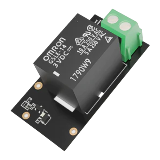
Documentation Center RAK13007 WisBlock Relay Module Datasheet Overview Figure 1: RAK13007 WisBlock Relay Module Description RAK13007 is a WisBlock Interface module that extends the WisBlock system to be used on isolated digital output applications. There is one digital output that is isolated by an electromechanical relay. The RAK13007 digital output is used to programmatically switch on/off devices operating at high voltage or high current applications. -
Page 10: Pin Definition
Documentation Center Figure 3: RAK13007 Block Diagram The RAK13007 uses one relay to isolate the output of the MCU. The dielectric strength between coil and contacts of a relay is 2500 V , 50/60 Hz 1min. WARNING!! ⚠ Figure 4: Safety Precaution Hardware The hardware specification is categorized into four (4) parts. -
Page 11: Electrical Characteristics
Documentation Center NOTE By default, IO4 is used as the Digital Output (DO) pin. DO pin can be changed by reworking some resistors on the PCB module. There are reserved options to change the GPIO to control DO. 3V3_S voltage output from the WisBlock Base that powers the RAK13007 module can be controlled by the WisBlock Core via WB_IO2 (WisBlock IO2 pin). -
Page 12: Mechanical Characteristics
Documentation Center Description Conditions Contact 100 mΩ Resistance Operate Time 10 ms max. Release Time 5 ms max. Operate: Approx. 0.6 ms Bounce Time Release: Approx. 7.2 ms Max. Switching Mechanical: 18,0000 operations/hr Frequency Electrical: 1,8000 operations/hr at rated load Insulation 100 MΩ... -
Page 13: Schematic Diagram
Documentation Center Figure 6: RAK13007 Mechanical Dimensions WisConnector PCB Layout Figure 7: WisConnector PCB Footprint and Recommendations Schematic Diagram Figure 8 shows the schematic of the RAK13007. -
Page 14: Relay Module
Documentation Center Figure 8: RAK13007 WisBlock Module Schematics Relay Module Figure 9 shows the schematic of the RAK13007 module. It uses 3V3_S for the relay coil power supply. Figure 9: RAK13007 WisBlock Relay Schematic Last Updated: 7/29/2022, 4:39:31 AM...
Need help?
Do you have a question about the WisBlock RAK13007 and is the answer not in the manual?
Questions and answers