Advertisement
Quick Links
Documentation Center
RAK13005 Quick Start Guide
Prerequisite
What Do You Need?
Before going through each and every step on using the RAK13005 WisBlock module, make sure to prepare the
necessary items listed below:
Hardware
RAK13005 WisBlock LIN Module - Controller/Master Mode
RAK13005 WisBlock LIN Module - Peripheral/Slave Mode
Your choice of
WisBlock Base
Your choice of
WisBlock Core
USB Cable
Li-Ion/LiPo battery (optional)
Solar charger (optional)
External power source ( 5.5 V to 27 V )
Software
Arduino
Download and install
Arduino IDE
To add the RAKwireless Core boards on your Arduino Boards Manager, install the
.
Product Configuration
Block Diagram
Hardware Setup
RAK13005 is a WisBlock LIN Module that extends the WisBlock system to be used on communication protocol
called Local Interconnect Network (LIN). This communication is initiated by the automotive industry for the
communication of in-vehicle devices on cars. Today, LIN is also used in other applications that require a robust
communication line. For more information about the RAK13005, refer to the Datasheet.
Pin Definition
.
RAKwireless Arduino BSP
Advertisement

Related Manuals for RAK WisBlock RAK13005


Summary of Contents for RAK WisBlock RAK13005
- Page 1 Documentation Center RAK13005 Quick Start Guide Prerequisite What Do You Need? Before going through each and every step on using the RAK13005 WisBlock module, make sure to prepare the necessary items listed below: Hardware RAK13005 WisBlock LIN Module - Controller/Master Mode RAK13005 WisBlock LIN Module - Peripheral/Slave Mode Your choice of WisBlock Base...
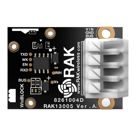
- Page 2 Documentation Center Figure 1: RAK13005 Pin Definition LIN Peripheral and Controller Mode Hardware Configuration RAK13005 supports both Controller(master) and Peripheral(slave) modes. The two modes uses the same RAK13005 circuit design and configuration is simply determined by an SMD resistor. The resistor location is shown in Figure 2.
- Page 3 Documentation Center The RAK13005 features a fast-crimping terminal connector to simplify and ensure the wiring process on the fields. The fast-crimping terminal can support cable with a width between 20 AWG to 24 AWG. The usual stripping length is around 6 to 7 mm. As shown in Figure 4, during the crimping process, you should first press down and maintain the spring head of the crimping terminal firmly, then insert the stripped cable head into the corresponding connector’s hole.
- Page 4 USB port of the board to configure the device. Not doing so might damage the battery or cause a fire. Make sure the battery wires match the polarity on the RAK WisBlock Base Board. Not all batteries have the same wiring.
- Page 5 Documentation Center Figure 8 is an illustration on how to use two RAK13005 LIN modules for communication applications. One RAK13005 is configured as Controller and the other RAK13005 is configured as Peripheral. The SMD resistors that set the mode are highlighted in a yellow box. Figure 8: Two RAK13005 Interconnection for Controller and Peripheral mode 1.
- Page 6 Documentation Center Figure 10: Open Arduino Library Manager Search for RAKwireless TLE7259 on the Library Manager text box. Select the latest version of the library then click Install button. Figure 11: Look for RAKwireless TLE7259 LIN Bus Library After successful installation, close the Arduino Library window.
- Page 7 Documentation Center Figure 12: RAKwireless TLE7259 LIN Bus Library Successfully Installed 3. Upload the Controller sketch. RAK13005_linbus_master Connect the first WisBlock with the RAK13005 module in Controller mode and select the RAK13005_linbus_master Figure 13: Open the code for the RAK13005 Controller Select the port where RAK4631 WisBlock Core is connected.
- Page 8 Documentation Center Figure 14: Select the Serial Port of RAK4631 for the RAK13005 LIN module in controller mode. Now, upload the code to the WisBlock Core. RAK13005_linbus_master Figure 15: Uploading RAK13005_linbus_master code...
- Page 9 Documentation Center Figure 16: Successful code Upload After the successful code upload, you can now open the Serial Monitor and see the Serial output. Figure 17: Serial Output of the RAK13005 Controller Mode 4. Upload the Peripheral sketch. RAK13005_linbus_slaver Connect the second WisBlock with the RAK13005 in Peripheral mode, then select RAK13005_linbus_slaver...
- Page 10 Documentation Center Figure 18: Open the code for the RAK13005 Peripheral Select the port, which is the additional port from the previous port for the controller. You should see two ports in your Arduino IDE. Figure 19: Select the Serial Port of RAK4631 for the RAK13005 LIN module in peripheral mode. After ensuring the port matching the RAK13005 LIN Peripheral, you can now upload the code.
- Page 11 Documentation Center Figure 20: Uploading the RAK13005_linbus_slaver code NOTE If you experience any error in compiling an example sketch, check the updated code for the RAK13005 WisBlock Core Module that can be found on the RAK13005 WisBlock Example Code Repository 5.
- Page 12 Documentation Center Figure 22 is an illustration on how to use two RAK13005 LIN modules for communication application. One RAK13005 is configured as Controller and the other RAK13005 is configured as Peripheral. The SMD resistors that set the mode are highlighted in a yellow box. Figure 22: Two RAK13005 Interconnection for Controller and Peripheral mode 1.
- Page 13 Documentation Center Figure 24: Open Arduino Library Manager Search for RAKwireless TLE7259 on Library Manager text box. Select the latest version then click Install button. Figure 25: Look for RAKwireless TLE7259 LIN Bus Library After successful installation, close the Arduino Library window.
- Page 14 Documentation Center Figure 26: RAKwireless TLE7259 LIN Bus Library Successfully Installed 3. Upload the Controller sketch. RAK13005_linbus_master Open the Controller sketch. RAK13005_linbus_master Connect the first WisBlock with the RAK13005 module in Controller mode and select the RAK13005_linbus_master Figure 27: Open the code for the RAK13005 Controller Select the port where RAK11200 WisBlock Core is connected.
- Page 15 Documentation Center Figure 28: Select the Serial Port of RAK11200 for the RAK13005 LIN module in controller mode. Now, upload the code to the WisBlock Core. RAK13005_linbus_master Figure 29: Uploading RAK13005_linbus_master code...
- Page 16 Documentation Center Figure 30: Successful code Upload After the successful code upload, you can now open the Serial Monitor and check the Serial output. Figure 31: Serial Output of the RAK13005 Controller Mode 4. Upload the Peripheral sketch. RAK13005_linbus_slaver Connect the second WisBlock with the RAK13005 in Peripheral mode then select RAK13005_linbus_slaver...
- Page 17 Documentation Center Figure 32: Open the code for the RAK13005 Peripheral Select the port, which is the additional port from the previous port for the controller. You should see two ports in your Arduino IDE. Figure 33: Select the Serial Port of RAK11200 for the RAK13005 LIN module in Peripheral mode. NOTE: RAK11200 requires the BOOT0 pin to be configured properly before uploading.
- Page 18 Documentation Center Figure 34: Uploading the RAK13005_linbus_slaver code NOTE If you experience any error in compiling an example sketch, check the updated code for the RAK13005 WisBlock Core Module that can be found on the RAK13005 WisBlock Example Code Repository 5.
- Page 19 Documentation Center Figure 36 is an illustration on how to use two RAK13005 LIN modules for communication application. One RAK13005 is configured as Controller and the other RAK13005 is configured as Peripheral. The SMD resistors that set the mode are highlighted in a yellow box. Figure 36: Two RAK13005 Interconnection for Controller and Peripheral mode 1.
- Page 20 Documentation Center Figure 38: Open Arduino Library Manager Search for RAKwireless TLE7259 on Library Manager text box. Select the latest version of the library then click Install button. Figure 39: Look for RAKwireless TLE7259 LIN Bus Library After successful installation, close the Arduino Library window.
- Page 21 Documentation Center Figure 40: RAKwireless TLE7259 LIN Bus Library Successfully Installed 3. Upload the Controller sketch. RAK13005_linbus_master Connect the first WisBlock with the RAK13005 module in Controller mode and select the RAK13005_linbus_master Figure 41: Open the code for the RAK13005 Controller Select the port where RAK11300 WisBlock Core is connected.
- Page 22 Documentation Center Figure 42: Select the Serial Port of RAK4631 for the RAK13005 LIN module in controller mode. Now, upload the code to the WisBlock Core. RAK13005_linbus_master Figure 43: Successful code upload After the successful code upload, you can now open the Serial Monitor and see the Serial output.
- Page 23 Documentation Center Figure 44: Serial Output of the RAK13005 Controller Mode 4. Upload the Peripheral sketch. RAK13005_linbus_slaver Connect the second WisBlock with the RAK13005 in Peripheral mode then select RAK13005_linbus_slaver Figure 45: Open the code for the RAK13005 Peripheral Select the port, which is the additional port from the previous port for the controller. You should see two ports in your Arduino IDE.
- Page 24 Documentation Center Figure 46: Select the Serial Port of RAK11300 for the RAK13005 LIN module in peripheral mode. After ensuring the port matching the RAK13005 LIN Peripheral, you can now upload the code. RAK13005_linbus_slaver Figure 47: Uploading the RAK13005_linbus_slaver code NOTE If you experience any error in compiling an example sketch, check the updated code for the RAK13005 WisBlock Core Module that can be found on the...
- Page 25 Documentation Center Figure 48: Serial Output of the RAK13005 Peripheral Mode To extend the use of the RAKwireless TLE7259 LIN Bus library, check the TLE7259 Library methods Last Updated: 7/29/2022, 10:17:19 PM...
-
Page 26: Overview Description
Documentation Center RAK13005 WisBlock LIN Module Datasheet Overview Description The RAK13005 is a Local Interconnect Network (LIN) transceiver module, used in automatic technologies that can be mounted on the IO slot of the WisBlock Base board. It is designed for in-vehicle networks using data transmission rates from 2.4 kBaud to 20 kBaud, and it uses the TLE7259-3 chip from Infineon. -
Page 27: Electrical Characteristics
Documentation Center Chipset Vendor Part number Infineon TLE7259-3 Pin Definition The RAK13005 WisBlock LIN module module comprises a standard 40-pin WisConnector. The WisConnector allows the RAK13005 module to be mounted on a WisBlock Base board, such as RAK5005-O. The pin order of the connector and the pinout definition is shown in Figure 2. -
Page 28: Schematic Diagram
Documentation Center Figure 4: RAK13005 WisBlock LIN Module Mechanic Drawing WisConnector PCB Layout Figure 5: WisConnector PCB Footprint and Recommendations Schematic Diagram Figure 5 shows the RAK13005 schematic. J2 is the LIN bus connector. J1 is the 40-pin WisConnector. VS is the LIN bus power supply pin. EN is the Enable input IO6 which is an active-high pin. - Page 29 Documentation Center NOTE: The MCU_WK pin (IO5) is connected to the Q1 transistor, and the Q1 collector is connected to the WK pin. Q1 works as an inverter, thus in normal operation, set MCU_WK to the high level. Figure 6: RAK13005 Schematic Diagram NOTE: With R5 soldered, the RAK13005 works as a LIN controller(master).
Need help?
Do you have a question about the WisBlock RAK13005 and is the answer not in the manual?
Questions and answers