Advertisement
Quick Links
Documentation Center
RAK19011 Quick Start Guide
This guide introduces the RAK19011 WisBlock Dual IO Base Board with Power Slot and how to use it.
Prerequisite
What Do You Need?
Before going through each and every step on using the RAK19011 WisBlock Dual IO Base Board with Power Slot,
make sure to prepare the necessary items listed below:
Hardware
Your choice of
WisBlock Base Power Module
RAK19011 WisBlock Dual IO Base Board with Power Slot
Your choice of
WisBlock Core
Your choice of
WisBlock Modules
It is highly recommended to also check the dedicated quick start guide that you can follow on various WisBlock
Modules. Each quick start guide of these modules contains the detailed steps on how to open the example codes
and upload them to the WisBlock Core.
Software
Based on the choice of the WisBlock Core, select a Development Environment:
Programming via Arduino IDE
RAKwireless BSP support for Arduino
In Arduino IDE, once you installed the BSP, the examples for WisBlock Core will be automatically included on
the list of examples.
Programming via PlatformIO IDE:
RAKwireless WisBlock modules in PlatformIO
Product Configuration
Overview
To give you a better understanding of how the WisBlock Base works, the block diagram RAK19011 is provided in
this section.
Block Diagram
The block diagram shown in Figure 1 shows the internal architecture and external interfaces of the RAK19011
board.
.
Advertisement

Related Manuals for RAK WisBlock RAK19011


Summary of Contents for RAK WisBlock RAK19011
- Page 1 Documentation Center RAK19011 Quick Start Guide This guide introduces the RAK19011 WisBlock Dual IO Base Board with Power Slot and how to use it. Prerequisite What Do You Need? Before going through each and every step on using the RAK19011 WisBlock Dual IO Base Board with Power Slot, make sure to prepare the necessary items listed below: Hardware Your choice of...
-
Page 2: Hardware Setup
Documentation Center Figure 1: RAK19011 WisBlock Dual IO Base Board with Power Slot block diagram The MCU in the WisBlock Core module offers the I2C, UART, and SPI data buses to the sensor and IO modules. Through these buses, the MCU can control and retrieve data from the sensors. The RAK19011 WisBlock Dual IO Base Board with Power Slot board connects all these modules. - Page 3 Documentation Center Figure 3: Alignment of WisConnector 2. Fit the connector. Tilt one end of the connector (header) less than 20 degrees, while do not apply force during this process, gently place the other end in parallel. Figure 4: Fit the WisConnector’s header inside of the socket 3.
- Page 4 Documentation Center Figure 7: Avoid applying uneven forces 6. When the buckling process is completed, check that the header and socket are kept in parallel. Figure 8: Correct way to buckle the WisConnector’s header to the socket 7. After buckling, if the header and socket are not in a parallel state (not fully assembled in one place), press with even force on both sides of the long side to complete the correct buckling.
- Page 5 Documentation Center Figure 11: Wrong way: Applying uneven forces to detach the header from the socket 3. The short-side of the connector can be pulled out asymmetrically, but apply the force vertically and avoid rotating the header. Figure 12: Wrong way: Do not rotate the header 4.
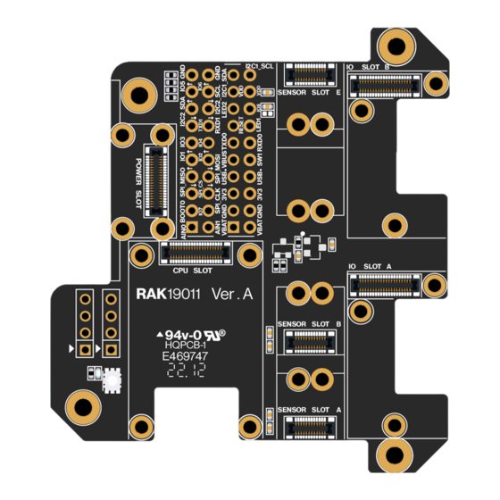
- Page 6 Documentation Center Figure 14: WisBlock Core silkscreen on the RAK19011 Base Board WisBlock Power A WisBlock Power module is designed to be installed on the Power slot of the RAK19011 WisBlock Dual IO Base Board with a Power Slot. As shown in Figure 15, the location is properly marked by silkscreen. Follow carefully the procedure defined in attaching a WisConnector section in order to attach a Core module.
- Page 7 Documentation Center Figure 16: WisBlock Sensor silkscreen on the RAK19011 Base Board WisBlock IO A WisBlock IO module is designed to be installed on the IO slot of the RAK19011 WisBlock Dual IO Base Board with Power Slot. There are two (2) IO slots in the RAK19011 WisBlock Dual IO Base Board with Power Slot. As shown in Figure 17, the location is properly marked by silkscreen.
-
Page 8: Software Setup
Documentation Center detached from the Base Board. See Figure 19 and Figure 20. Figure 19: Detaching silkscreen on the WisBlock module Figure 20: Applying even forces on the proper location of a WisBlock module to detach the module from the Base Board Software Setup The WisBlock Core is designed to be interfaced with other WisBlock Modules like sensors, displays, and other interfaces. -
Page 9: Specifications Overview
Documentation Center RAK19011 WisBlock Dual IO Base Board with Power Slot Datasheet WisBlock Dual IO Base Board with Power Slot Overview RAK19011 is a WisBlock Dual IO Base Board with Power Slot board that connects WisBlock Core, Wisblock Power, and WisBlock Modules. - Page 10 Documentation Center Figure 2: RAK19011 WisBlock Base block diagram Hardware The hardware specification is categorized into six parts. It discusses the interfacing, pinouts, and their corresponding functions and diagrams. It also covers the electrical, mechanical, and environmental parameters that include the tabular data of the functionalities and standard values of the RAK19011 WisBlock Dual IO Base Board with Power Slot.
- Page 11 Documentation Center NOTE BOOT pin is used on startup configuration or sequence of the WisBlock Core connected to it. It is commonly used for uploading the bootloader and/or application firmware. The requirements of the state of the BOOT pin depend on the specific model of the WisBlock Core used.
- Page 12 Documentation Center Pin Number Function Name of WisBlock Base Pin Number Function Name of WisBlock Base USB+ USB– VBUS TXD0 RXD0 RESET LED1 LED2 I2C1_SDA I2C1_SCL AIN0 AIN1 BOOT0 SPI_CS SPI_CLK SPI_MISO SPI_MOSI TXD1 RXD1 I2C2_SDA I2C2_SCL As for the following table, it shows the definition of each pin of the WisBlock Core connector: Pin Number Pin Name Type...
- Page 13 Documentation Center Pin Number Pin Name Type Description VBUS USB VBUS Switch signal for customer's control TXD0 MCU UART0 TX signal RXD0 MCU UART0 RX signal RESET Connected to the reset switch, for MCU reset LED1 LED for battery charging indication LED2 LED for custom usage LED3...
- Page 14 Documentation Center Pin Number Pin Name Type Description General purpose IO General purpose IO Ground Ground Connector for WisBlock Power Module The WisPower module connector is a 40-pin board-to-board connector. It is a high-speed and high-density connector, with an easy attaching mechanism.
- Page 15 Documentation Center Pin Number Function Name of WisBlock Base Pin Number Function Name of WisBlock Base I2C2_SDA I2C2_SCL As for the following table, it shows the definition of each pin of the WisBlock Power slot connector: Pin Number Pin Name Type Description VBAT...
- Page 16 Documentation Center Pin Number Pin Name Type Description AIN0 Analog input for ADC AIN1 Analog input for ADC Not connected Not connected SPI_CS SPI chip select signal SPI_CLK SPI clock signal SPI_MISO SPI MISO signal SPI_MOSI SPI MOSI signal Not connected Not connected Not connected Not connected...
- Page 17 Documentation Center Figure 8: WisBlock 24-pin module connector Pinout definition for standard size slot (A-D): Number Number TXD0 SPI_CS SPI_CS SPI_CS SPI_CS SPI_CLK SPI_CLK SPI_CLK SPI_CLK SPI_MISO SPI_MISO SPI_MISO SPI_MISO SPI_MOSI SPI_MOSI SPI_MOSI SPI_MOSI I2C1_SCL I2C1_SCL I2C1_SCL I2C1_SCL I2C1_SDA I2C1_SDA I2C1_SDA I2C1_SDA 3V3_S...
- Page 18 Documentation Center Connector F Connector E Pin Number Pin Number Connector E Connector F RXD0 RXD1 As for the following table, it shows the pin name and description of each pin in the 24-pin WisBlock module connector. Pin Number Pin Name Type Description TXD1...
- Page 19 Documentation Center Pin Number Pin Name Type Description Not connected Ground RXD1 UART RX signal Connector for WisBlock IO Slot The WisBlock Module IO Slot connector, as shown in Figure 9, is a 40-pin board-to-board connector. NOTE The two WisBlock 40-pin connectors have the same connections for all IO, signal, and serial pins (UART, SPI, I2C). Figure 9: WisBlock IO slot connector Pinout definition for IO slot: Connector B...
- Page 20 Documentation Center Connector B Connector A Pin Number Pin Number Connector A Connector B TXD1 TXD1 RXD1 RXD1 I2C2_SDA I2C2_SDA I2C2_SCL I2C2_SCL As for the following table, it shows the pin name and description of the WisBlock IO module connector. Pin Number Pin Name Type...
- Page 21 Documentation Center Pin Number Pin Name Type Description AIN0 Analog input for ADC AIN1 Analog input for ADC Not connect Not connect SPI_CS SPI chip select signal SP_CLK SPI clock SPI_MISO SPI MISO signal SPI_MOSI SPI MOSI signal General purpose IO Used for 3V3_S enable General purpose IO General purpose IO...
- Page 22 Documentation Center Ratings Maximum Value Unit 2000 NOTE The RAK19011, like any electronic equipment, is sensitive to electrostatic discharge (ESD). Improper handling can cause permanent damage to the module. Current Consumption The RAK19011 is designed for low-power IoT products. Its power supply uses a high-efficiency low ground current regulator. When there is no module on RAK19011, the leakage current is lower than 2 µA.
- Page 23 Documentation Center Figure 11: RAK19011 mechanical dimensions WisConnector PCB Layout Figure 12: WisConnector PCB footprint and recommendations Environmental Characteristics The table below lists the operation and storage temperature requirements of RAK19011:...
- Page 24 Documentation Center Parameter Minimum Typical Maximum Parameter Minimum Typical Maximum Operational temperature range –35 ºC +25 ºC +75 ºC Extended temperature range –40 ºC +25 ºC +80 ºC Storage temperature range –40 ºC +25 ºC +80 ºC Schematic Diagram The component schematic diagram of the RAK19011 is shown in Figure 13 and Figure 14. Figure 13: RAK19011 schematic diagram 1...
- Page 25 Documentation Center Figure 14: RAK19011 schematic diagram 2 Last Updated: 7/29/2022, 10:17:19 PM...
Need help?
Do you have a question about the WisBlock RAK19011 and is the answer not in the manual?
Questions and answers