
Related Manuals for RAK WisLink-Cellular RAK2011


Summary of Contents for RAK WisLink-Cellular RAK2011
- Page 1 User’s Manual WisLink-Cellular RAK2011 ™ Version 1.0 | August 2018 Please visit our website (www.rakwireless.com) for the latest copy of this manual.
- Page 2 Author: Gan, Penn WisLink-Cellular RAK2011 Approval: Ken Yu V 1.0 | Aug. 2018 ABOUT RAKWIRELESS Rakwireless is a pioneer in providing innovated and diverse cellular and LoRa connectivity solutions for IoT edge devices. It’s patented, modularized, simplified design significantly help address diverse IoT applications and accelerate their time-to-market.
-
Page 3: Table Of Contents
Author: Gan, Penn WisLink-Cellular RAK2011 Approval: Ken Yu V 1.0 | Aug. 2018 Table of Contents 1. Overview................................4 1.1 Introduction....................................4 1.2 Package Content..................................4 2. BG96 LPWA IoT Cellular Arduino Shield......................5 2.1 Overview......................................5 2.2 Functional Diagram..................................6 2.3 Interfaces....................................... -
Page 4: Overview
RAK2011 can be used as a development platform in tandem with microcontrollers/microprocessors for IoT applications or can be used as standalone. It is in full compliance with FCC, CE, RoHS and Japan TELEC/JATE. 1.2 Package Content A full WisLink-Cellular RAK2011 retail package includes: BG96 LPWA IoT Cellular Arduino Shield ... -
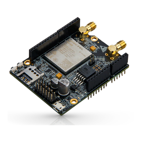
Page 5: Bg96 Lpwa Iot Cellular Arduino Shield
Author: Gan, Penn WisLink-Cellular RAK2011 Approval: Ken Yu V 1.0 | Aug. 2018 2. BG96 LPWA IoT Cellular Arduino Shield 2.1 Overview The picture below shows the top view of the BG96 LPWA IoT Cellular Arduino Shield. The picture below shows the underside of the BG96 LPWA IoT Cellular Arduino Shield. -
Page 6: Functional Diagram
Author: Gan, Penn WisLink-Cellular RAK2011 Approval: Ken Yu V 1.0 | Aug. 2018 2.2 Functional Diagram Block diagram below shows internal architecture and external interfaces:... -
Page 7: Interfaces
Author: Gan, Penn WisLink-Cellular RAK2011 Approval: Ken Yu V 1.0 | Aug. 2018 2.3 Interfaces It is built around Quectel BG96 LPWA IoT cellular module and provides the following interfaces, headers, jumpers, buttons and connectors: Micro-B USB Micro SIM Card Slot ... -
Page 8: Cellular (Lte/Gsm) Operating Frequency
Author: Gan, Penn WisLink-Cellular RAK2011 Approval: Ken Yu V 1.0 | Aug. 2018 2.5 Cellular (LTE/GSM) Operating Frequency The table below lists all the supported cellular (LTE/GSM) operating frequency: 3GPP Band Transmit (MHz) Receive (MHz) 1920 ~ 1980 2110 ~ 2170... -
Page 9: Pcm Voice Header
Author: Gan, Penn WisLink-Cellular RAK2011 Approval: Ken Yu V 1.0 | Aug. 2018 BG96 LPWA IoT Cellular Arduino Shield Arduino header signal definition is shown below: Name Pin# Description UART1_TXD UART3_TXD UART1_RXD Receive cellular (LTE/GSM) data Ring indicator Data Terminal Ready (sleep mode control) -
Page 10: Analog Input / Digital I/O Header
Author: Gan, Penn WisLink-Cellular RAK2011 Approval: Ken Yu V 1.0 | Aug. 2018 Reference design for external CODEC extension board is shown below: 2.8 Analog Input / Digital I/O Header A standard 2x3 (2.54mm) male header is used to provide 2x analog input (ADC0 and ADC1 and 2x... -
Page 11: Debug Header
Author: Gan, Penn WisLink-Cellular RAK2011 Approval: Ken Yu V 1.0 | Aug. 2018 2.9 Debug Header A standard 1x4 (2.54mm) male header is used to provide a serial port (UART2) interface for debug and log output at 115200bps baud rate. Debug... -
Page 12: Usb Boot Jumper
Author: Gan, Penn WisLink-Cellular RAK2011 Approval: Ken Yu V 1.0 | Aug. 2018 2.11 USB Boot Jumper A Standard 1x2 USB Boot header (once closed) is used to force BG96 LPWA IoT Cellular Arduino Shield to boot from USB port for firmware upgrade. -
Page 13: Power Requirements
Author: Gan, Penn WisLink-Cellular RAK2011 Approval: Ken Yu V 1.0 | Aug. 2018 2.15 Power Requirements BG96 LPWA IoT Cellular Arduino Shield can be powered by +5V coming out of MCU baseboard via Arduino header (POWER) if used as an Arduino Shield. -
Page 14: Antenna
Author: Gan, Penn WisLink-Cellular RAK2011 Approval: Ken Yu V 1.0 | Aug. 2018 3. Antenna 3.1 Cellular (LTE/GSM) Antenna 3.1.1 Overview The cellular (LTE/GSM) antenna for BG96 LPWA IoT Cellular Arduino Shield covers working frequency band from 824MHz to 2690MHz. -
Page 15: Cellular (Lte/Gsm) Antenna Parameter
Author: Gan, Penn WisLink-Cellular RAK2011 Approval: Ken Yu V 1.0 | Aug. 2018 3.1.3 Cellular (LTE/GSM) Antenna Parameter Voltage Standard Wave Radio (VSWR) plot is shown below: Freq. (MHz) VSWR 1710 1880 2170 3.1.4 Smith Plot Smith Plot is shown below:... -
Page 16: Radiation Pattern On H-Plane
Author: Gan, Penn WisLink-Cellular RAK2011 Approval: Ken Yu V 1.0 | Aug. 2018 3.1.5 Radiation Pattern on H-Plane... -
Page 17: Radiation Pattern On E1-Plane
Author: Gan, Penn WisLink-Cellular RAK2011 Approval: Ken Yu V 1.0 | Aug. 2018 3.1.6 Radiation Pattern on E1-Plane... -
Page 18: Radiation Pattern On E2-Plane
Author: Gan, Penn WisLink-Cellular RAK2011 Approval: Ken Yu V 1.0 | Aug. 2018 3.1.7 Radiation Pattern on E2-Plane 3.1.8 UGain and Efficiency Table Frequency 7.90E+08 1.8309 Efficiency Gain (dBi) (Hz) 8.00E+08 1.843967 7.00E+08 1.632948 8.06E+08 1.714366 7.10E+08 1.826395 8.10E+08 2.215538 7.20E+08... - Page 19 Author: Gan, Penn WisLink-Cellular RAK2011 Approval: Ken Yu V 1.0 | Aug. 2018 8.80E+08 1.960958 9.20E+08 2.081987 8.84E+08 1.930333 9.30E+08 2.005751 8.94E+08 2.347337 9.40E+08 2.128994 9.00E+08 2.192946 9.50E+08 2.305449 9.10E+08 2.265394 9.60E+08 2.233022 Frequency 1.94E+09 0.407999 Efficiency Gain (dBi) (Hz) 1.96E+09...
-
Page 20: Gps Antenna
Author: Gan, Penn WisLink-Cellular RAK2011 Approval: Ken Yu V 1.0 | Aug. 2018 3.2 GPS Antenna 3.2.1 Overview The GPS antenna for BG96 LPWA IoT Cellular Arduino Shield is shown below: 3.2.2 GPS Antenna Dimensions 3.2.3 GPS Environmental Requirements The antenna environmental requirements are listed in the table below:... -
Page 21: Gps Antenna Parameter
Author: Gan, Penn WisLink-Cellular RAK2011 Approval: Ken Yu V 1.0 | Aug. 2018 3.2.4 GPS Antenna Parameter Antenna specifications are listed in the table below: Post Environmental Item Specifications Tolerance Range of Receiving Frequency 1575.42±1.1 ±2.5 Center Frequency (MHz) w/ 30mm 1575.42... -
Page 22: Usage Model By Interface
Author: Gan, Penn WisLink-Cellular RAK2011 Approval: Ken Yu V 1.0 | Aug. 2018 4. Usage Model by Interface 4.1 User USB Interface 4.1.1 Install USB Driver If it is the first time to connect BG96 LPWA IoT Cellular Arduino Shield to a Windows PC, install the BG96 USB driver first. - Page 23 Author: Gan, Penn WisLink-Cellular RAK2011 Approval: Ken Yu V 1.0 | Aug. 2018 https://www.rakwireless.com/en/download/Cellular/WisLTE After sending AT\r\n, The module will return AT\r\nOK, this means the BG96 module is working normally. You can send more AT commands to control the module. For more AT commands, please read the documents BG96 AT Commands Manual.
-
Page 24: Nb-Iot Udp Communication Test
V 1.0 | Aug. 2018 4.1.3 NB-IoT UDP Communication Test Plug in NB-IoT SIM card. Connect WisLink-Cellular RAK2011 to a Windows PC. Select Quectel USB AT Port corresponding to the COM port. Open the serial port tools. Send the AT commands listed below to have the BG96 module find a NB-IoT network;... - Page 25 Author: Gan, Penn WisLink-Cellular RAK2011 Approval: Ken Yu V 1.0 | Aug. 2018 After setting, send AT + CSQ to check network signal strength, if there is a signal value, it indicates that it has connected to NB-IoT network. You can also send AT + CGREG? to check the connection status of the network to determine whether to connect to the network: After connecting to the network, you need to set up the APN and activate the APN network.
- Page 26 Author: Gan, Penn WisLink-Cellular RAK2011 Approval: Ken Yu V 1.0 | Aug. 2018 After activating the APN, you can establish a UDP connection; (In China Telecom’s NB-IoT network, you must first inform the operator your server IP address. The operator will make binding before the connection is successful.
-
Page 27: Gps Function Test
Author: Gan, Penn WisLink-Cellular RAK2011 Approval: Ken Yu V 1.0 | Aug. 2018 4.1.4 GPS Function Test Plug in the module GPS antenna. Select Quectel USB AT Port corresponding to the COM port. Open the serial port tools. Send the commands listed below to control the module's GPS capabilities. (For detailed GPS command... - Page 28 Author: Gan, Penn WisLink-Cellular RAK2011 Approval: Ken Yu V 1.0 | Aug. 2018 Revision History Revision Description Date Initial version July 23, 2018 About RAKwireless: Shenzhen RAKwireless Technology is a pioneer in providing innovated Lego-like IoT module solutions for the three critical elements of IoT edge devices – edge computing, cloud connectivity, and node sensing.
Need help?
Do you have a question about the WisLink-Cellular RAK2011 and is the answer not in the manual?
Questions and answers