Table of Contents
Advertisement
Quick Links
Documentation Center
RAK19012 Quick Start Guide
Prerequisite
What Do You Need?
Before going through each and every step on using the RAK19012 WisBlock USB LiPo Solar Power Slot Module,
make sure to prepare the necessary items listed below:
Hardware
RAK19012 WisBlock USB LiPo Solar Power Slot Module
Your choice of
WisBlock Base board with Power Slot
Your choice of
WisBlock Core
Li-Ion/LiPo battery
Solar charger
Software
Arduino
Download and install the
To add the RAKwireless Core boards to your Arduino Boards Manager, install the
Product Configuration
Hardware Setup
RAK19012 should be attached to the power slot connector of WisBlock Base board with power slot. It is a power
board that provides the same features and interfaces that standard WisBlock Base boards provide - USB C
connector, battery and solar panel connector, LED indicators, and reset button.
WARNING
⚠
RAK19012 only supports WisBlock Base boards with Power Slot. It is not compatible with all WisBlock
Base boards.
For more information about RAK19012, refer to the Datasheet.
RAK19012 Connection to WisBlock Base board with
Power Slot
Arduino IDE
.
RAKwireless Arduino BSP
.
Advertisement
Table of Contents

Related Manuals for RAK WisBlock RAK19012


Summary of Contents for RAK WisBlock RAK19012
- Page 1 Documentation Center RAK19012 Quick Start Guide Prerequisite What Do You Need? Before going through each and every step on using the RAK19012 WisBlock USB LiPo Solar Power Slot Module, make sure to prepare the necessary items listed below: Hardware RAK19012 WisBlock USB LiPo Solar Power Slot Module Your choice of WisBlock Base board with Power Slot Your choice of...
-
Page 2: Disassembling Procedure
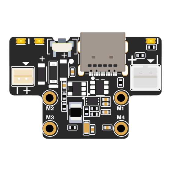
Documentation Center Figure 1: RAK19012 pinout and connector assignments NOTE The voltage of the battery must not exceed 4.3 V. Assembling and Disassembling of WisBlock Modules Assembling Procedure RAK19012 module can be mounted on the power slot of the WisBlock Base board, as shown in Figure 2. Also, always secure the connection of the WisBlock module by using compatible screws. - Page 3 Documentation Center Figure 3: Removing screws from the WisBlock module 2. Once the screws are removed, check the silkscreen of the module to find the correct location where force can be applied. Figure 4: Detaching silkscreen on the WisBlock module 3.
-
Page 4: Rechargeable Battery
Figure 6. The matching connector for the rechargeable battery wires is a JST PHR-2 2 mm pitch female cable assembly for the rechargeable battery connector is also available for purchase in RAK store ⚠ WARNING Battery can cause harm if not handled properly. -
Page 5: Software Setup
Documentation Center Software Setup There is no software required to use RAK19012. But to control the two user LEDs and monitor the battery voltage, they must be attached to a WisBlock Base and WisBlock Core. WisBlock Examples Repository To quickly build your IoT device with less hassle, example codes for WisBlock Core are provided. You can access the codes on the WisBlock Example code repository . -
Page 6: Specifications
Documentation Center RAK19012 WisBlock USB LiPo Solar Power Slot Module Datasheet Overview Description RAK19012 WisBlock USB LiPo Solar Power Slot Module is a power board that comprises a USB C connector, battery connector with an onboard charger, solar panel connector, LED indicator for charge status, two user- configurable LEDs, a reset button, and a power connector that can connect with the WisBlock Base board. - Page 7 Documentation Center Figure 2: RAK19012 mounting mechanism on a WisBlock Base module Hardware The hardware specification is categorized into six parts. It discusses the interfacing, pinouts, and their corresponding functions and diagrams of the module. It also covers the electrical, mechanical, and environmental characteristics that include the tabular data of the functionalities and standard values of the RAK19012 WisBlock LiPo Solar Power Slot Module.
-
Page 8: Reset Push Button
Documentation Center Figure 4: Battery and solar panel connector polarity LEDs Three LEDs are used to indicate the operating status. Below are the functions of the LEDs: �� Red LED - Connected to the charger chip to indicate the charger status. When the battery is charging, this red LED is on. -
Page 9: Electrical Characteristics
Documentation Center Figure 5: RAK19012 pinout diagram Electrical Characteristics Absolute Maximum Ratings The Absolute Maximum Ratings of the device are shown in the table below. The stress ratings are the functional operation of the device. ⚠ W ARNING 1. If the stress rating goes above what is listed, it may cause permanent damage to the device. 2. -
Page 10: Mechanical Characteristic
Documentation Center Parameter Value Standard voltage 3.7 V Charging voltage 4.2 V Capacity As required Discharge current At least 500 mA NOTE When using a solar panel, you can't use a non-rechargeable battery. Mechanical Characteristic Board Dimensions The mechanical dimensions of the RAK19012 module are shown in Figure 6 below. Figure 6: RAK19012 mechanical dimensions WisConnector PCB Layout... -
Page 11: Environmental Characteristics
Documentation Center Figure 7: WisConnector PCB footprint and recommendations Environmental Characteristics The table below lists the operation and storage temperature requirements of RAK19012: Parameter Minimum Typical Maximum Operational temperature range –35 ºC +25 ºC +75 ºC Extended temperature range –40 ºC +25 ºC +80 ºC Storage temperature range... - Page 12 Documentation Center Figure 8: RAK19012 USB LiPo Solar Power Slot Module schematics Last Updated: 7/18/2022, 6:55:21 AM...
Need help?
Do you have a question about the WisBlock RAK19012 and is the answer not in the manual?
Questions and answers