
Subscribe to Our Youtube Channel
Related Manuals for Moxa Technologies UC-8580 Series


Summary of Contents for Moxa Technologies UC-8580 Series
- Page 1 UC-8580 Series Hardware User Manual Version 2.1, November 2022 www.moxa.com/product © 2022 Moxa Inc. All rights reserved.
- Page 2 UC-8580 Series Hardware User Manual The software described in this manual is furnished under a license agreement and may be used only in accordance with the terms of that agreement. Copyright Notice © 2022 Moxa Inc. All rights reserved. Trademarks The MOXA logo is a registered trademark of Moxa Inc.
-
Page 3: Table Of Contents
Dimensions ............................7 LED Indicators ............................8 Reset Button ............................8 Hardware Connection Description......................9 Installing the UC-8580 Series ........................9 Wiring Requirements ..........................9 Connecting the Power ........................10 Grounding the Unit ........................11 Connecting Data Transmission Cables ....................12 Connecting to an Ethernet Network .................... -
Page 4: Introduction
1. Introduction Thank you for using Moxa’s UC-8580 Series computer. The UC-8580 Series computer is a programmable communication-centric gateway offering a rich variety of communication interfaces such as Ethernet, serial, and digital inputs/outputs. This EN 50155-compliant computer is built for rail applications and comes with multiple wireless WAN gateway interfaces making it an ideal choice for building wireless communication infrastructure with 802.11 a/b/g/n/ac, and for LTE data collection and transmission. -
Page 5: Product Features
Product Features The UC-8580 Series computer includes the following features: Armv7 Cortex-A7 dual-core 1 GHz processor • 1 GB DDR3L SDRAM • • 8 GB eMMC for OS 1 mSATA slot for expansion storage • • 2 auto-sensing 10/100/1000 Mbps Ethernet M12 ports 1 USB 3.0/2.0 host with Type A connector... -
Page 6: Hardware Introduction
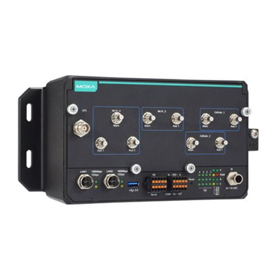
UC-8580 allow you to connect different devices for wireless operation, and the reliable and stable hardware platform lets you devote your attention to developing your applications. Appearance Front View SMA Model UC-8580 Series Hardware User Manual... -
Page 7: Dimensions
QMA Model Dimensions Units: mm (in) UC-8580 Series Hardware User Manual... -
Page 8: Led Indicators
The R LED will flash for 5 seconds and then maintain a steady glow when the system has rebooted. All system configurations will be reset to the factory default once the computer restarts. The illustration below shows an SMA model. UC-8580 Series Hardware User Manual... -
Page 9: Hardware Connection Description
The rule of thumb is that wiring that shares similar electrical characteristics can be bundled together. Keep input wiring and output wiring separate. • It is advisable to label the wiring to all devices in the system for easy identification. • UC-8580 Series Hardware User Manual... -
Page 10: Connecting The Power
Connecting the Power Connect the 24 to 110 VDC power line with M12 A-coded connector to the UC-8580 Series computer. If the power is supplied properly, the P LED will glow a solid green after a 25 to 30-second delay. The power input... -
Page 11: Grounding The Unit
This product is intended to be mounted on a well-grounded mounting surface, such as a metal panel. The grounding connector is located on the front panel. Connect the grounding wire to an appropriate grounded metal surface. UC-8580 Series Hardware User Manual... -
Page 12: Connecting Data Transmission Cables
The figure is based on the SMA model. NOTE If you are using your own Ethernet cable, make sure that the pin assignment on the connector of the Ethernet cable matches the pin assignment shown below. UC-8580 Series Hardware User Manual... -
Page 13: Connecting To A Serial Device
Connecting Digital Input/Output Devices The UC-8580 computer comes with a 3-channel digital input and 3-channel digital output terminal block that you can use to connect your digital devices. The DI/O pin assignments and wiring methods are shown below: UC-8580 Series Hardware User Manual... -
Page 14: Connecting A Usb Device
Connecting a USB Device The UC-8580 computer is provided with a USB 3.0 port on the front panel for connecting a USB device. UC-8580 Series Hardware User Manual... -
Page 15: Connecting Wi-Fi/Cellular Modules And Installing Antennas
1, insert SIM cards in the SIM 1-1 and SIM 1-2 slots. The SIM cards for the cellular module in socket 3 should be inserted in the SIM 3-1 and SIM 3-2 slots. UC-8580 Series Hardware User Manual... - Page 16 The Wi-Fi/cellular module package includes 1 wireless (Wi-Fi or cellular) module, 2 or 3 antenna cables and connectors, 1 black tape, 1 tag sheet, 2 screws, 2 locking washers, and 2 nuts. Accessories for the SMA Model Accessories for the QMA Model UC-8580 Series Hardware User Manual...
- Page 17 Follow these steps to install a wireless (Wi-Fi/cellular) module. Remove the plastic protective film on the thermal pads that come attached to the wireless module. Insert the wireless module in the designated socket and tighten the two screws on the module. UC-8580 Series Hardware User Manual...
- Page 18 D shaped connector tube with the antenna hole before you do so. Secure the antenna connectors to the front panel by inserting the locking washers through the connector tube followed by the nut and then tightening the nut onto the threaded protection ring. UC-8580 Series Hardware User Manual...
- Page 19 Use the procedure described above to install other Wi-Fi or cellular modules. NOTE The Wi-Fi module installed in socket 4 requires three antennas. Make sure all three antennas are installed and secured properly before you use the module. UC-8580 Series Hardware User Manual...
-
Page 20: Installing Sim Cards For The Cellular Modules
Each cellular module supports 2 SIM cards. To install SIM cards for the cellular modules, do the following: Find the location of the SIM card socket. Pull up the SIM card holder and insert the SIM card. Push down the SIM card holder until the SIM card is secured in place. UC-8580 Series Hardware User Manual... -
Page 21: Installing The Msata Module
It is the left most socket that you see when you open the front panel of the computer. Insert the mSATA module in the socket. Fasten the two screws on the module to secure the module. UC-8580 Series Hardware User Manual...
Need help?
Do you have a question about the UC-8580 Series and is the answer not in the manual?
Questions and answers