
Related Manuals for Moxa Technologies UC-8580 Series


Summary of Contents for Moxa Technologies UC-8580 Series
- Page 1 UC-8580 Series Quick Installation Guide Version 3.1, January 2021 Technical Support Contact Information www.moxa.com/support 2021 Moxa Inc. All rights reserved. P/N: 1802085800012 *1802085800012*...
- Page 2 -25 to 55°C (-13 to 131°F) UC-8580-T-Q-LX -40 to 70°C (-40 to 158°F) UC-8580-T-CT-Q-LX -40 to 70°C (-40 to 158°F) The UC-8580 Series computer is shipped with the following items: • UC-8580 Series computer • CBL-4PINDB9F-100: 4-pin pin header to DB9 female console port cable, 100 cm •...
-
Page 3: Led Indicators
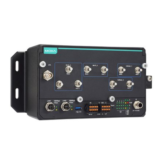
Front View SMA Model QMA Model LED Indicators Refer to the following table for the LED indicator definitions. LED Name Status Function Green Power is on No power input or any other power-input error Green System is ready System is booting up, OS boot-up failure, or any other system initialization error Ethernet Green... -
Page 4: Installing The Computer
LED Name Status Function Green Data is being accessed from either the eMMC or the mSATA module No data is being accessed Programmable LED for user-defined function Wireless Green The number of glowing LEDs indicate the wireless signal strength as follows: 3 Green: Excellent 2 Green: Good 1 Green: Poor... -
Page 5: Connecting The Power
ATTENTION Safety First! Be sure to disconnect the power cord before installing and/or wiring your UC-8580 computer. Wiring Caution! Calculate the maximum possible current in each power wire and common wire. Observe all electrical codes dictating the maximum current allowable for each wire size. If the current goes above the maximum ratings, the wiring could overheat, causing serious damage to your equipment. -
Page 6: Connecting To The Network
SMA Model Connecting to the Network The pin assignments for the UC-8580 computer’s Ethernet port are shown in the following figure. If you are using your own Ethernet cable, make sure that you match the pin assignment on the connector of the Ethernet cable to the pin assignment shown below. -
Page 7: Connecting Digital Input/Output Devices
RS-232 RS-422 TxD+ TxD- RxD+ RxD- RS-485 – – DATA+ DATA- Connecting Digital Input/Output Devices The UC-8580 computer comes with a 3-channel digital input and a 3-channel digital output terminal block that you can use to connect your digital devices. The DI/O pin assignments and wiring methods are shown below. - Page 8 Connecting the Wi-Fi/Cellular Module and Antenna The UC-8580 computer is provided with four sets of antenna holes for installing antennas for the Wi-Fi and cellular modules. Unfasten the four screws on the front panel and lift up the panel to check the location of the Wi-Fi/cellular module sockets.
- Page 9 Accessories for the SMA Model Accessories for the QMA Model To install a wireless (Wi-Fi/cellular) module, do the following: 1. Remove the plastic protective 2. Insert the wireless module in film on the thermal pads the designated socket and attached to the wireless tighten the two screws on the module.
- Page 10 3. Attach the flat end of an antenna cable to the connector marked MAIN on the module and insert the other end of the cable (with the connector tube) into the antenna hole marked MAIN on the front panel of the computer. You must first remove the black cover on the antenna hole and insert the connector tube through the back side of the front panel...
-
Page 11: Installing Sim Cards
6. Connect the antennas to the connectors on the front panel. Refer to the following illustration of an SMA model for the specific location of each antenna connector, including a connector for a GPS antenna. Use the procedure described above to install other Wi-Fi or cellular modules. -
Page 12: Installing The Msata Module
3. Push down the SIM-card holder until the SIM card is secured in place. Installing the mSATA Module The UC-8580 computer is provided with one storage socket for installing an mSATA module. To install the mSATA module, do the following: 1.
Need help?
Do you have a question about the UC-8580 Series and is the answer not in the manual?
Questions and answers