Moxa Technologies UC-8580-T-CT-LX Hardware User Manual
Uc-8580 series
Hide thumbs
Also See for UC-8580-T-CT-LX:
- Quick installation manual (12 pages) ,
- Quick installation manual (13 pages) ,
- Hardware user manual (21 pages)

Related Manuals for Moxa Technologies UC-8580-T-CT-LX


Summary of Contents for Moxa Technologies UC-8580-T-CT-LX
- Page 1 UC-8580 Series Hardware User’s Manual Edition 1.0, August 2017 www.moxa.com/product © 2017 Moxa Inc. All rights reserved.
- Page 2 UC-8580 Series Hardware User’s Manual The software described in this manual is furnished under a license agreement and may be used only in accordance with the terms of that agreement. Copyright Notice © 2017 Moxa Inc. All rights reserved. Trademarks The MOXA logo is a registered trademark of Moxa Inc.
-
Page 3: Table Of Contents
Table of Contents Introduction ............................1-1 Model Descriptions and Package Checklist ....................1-2 Product Features ..........................1-2 Hardware Specifications ........................1-3 Hardware Block Diagram ........................1-5 Hardware Introduction ........................2-1 Appearance ............................2-2 Dimensions ............................2-2 LED Indicators ............................ 2-3 Reset Button ............................ -
Page 4: Introduction
Introduction Thank you for using Moxa’s UC-8580 Series computer. The UC-8580 Series computer is a programmable communication-centric gateway offering a rich variety of communication interfaces, such as Ethernet, serial, and digital inputs/outputs. This EN 50155-compliant computer is built for rail applications and comes with multiple wireless WAN gateway interfaces making it an ideal choice for building wireless communication infrastructure with 802.11b/g/n/ac and LTE data collection and transmission. -
Page 5: Model Descriptions And Package Checklist
• supporting up to 4 wireless modules, with -40 to 70°C operating temperature range UC-8580-T-CT-LX: Programmable multiple-wireless computing platform for rail onboard applications, • supporting up to 4 wireless modules, with -40 to 70°C operating temperature range and conformal coating The UC-8580 Series computer is shipped with the following items. -
Page 6: Hardware Specifications
UC-8580 Series Hardware Introduction Hardware Specifications Hardware Specifications Computer CPU: ARMv7 Cortex-A7 dual-core 1GHz processor USB: USB 3.0/2.0 host x 1 (type A connector) DRAM: 1 GB DDR3L SDRAM OS (pre-installed): Debian ARM 8 (Kernel 4.1) Storage Expansion: 1 mSATA slot for storage expansion Ethernet Interface LAN: 2 auto-sensing 10/100/1000 Mbps ports (M12) Magnetic Isolation Protection: 1.5 kV built-in... - Page 7 UC-8580 Series Hardware Introduction Storage: storage x 1 Cellular/Wi-Fi: Cellular/Wi-Fi x 12 Button Reset: Reset the device to factory defaults button x 1 Physical Characteristics Housing: AI 5052 + ADC 12 Weight: 2.2 kg (4.86 lb) Dimensions: 220 x 134 x 88.3 mm (8.66 x 5.28 x 3.48 in) without wall mount ear 270 x 134 x 88.3 mm (10.63 x 5.28 x 3.48 in) with wall mount ear Mounting: wall Environmental Limits...
-
Page 8: Hardware Block Diagram
UC-8580 Series Hardware Introduction Hardware Block Diagram... -
Page 9: Hardware Introduction
Hardware Introduction The UC-8580 computer is compact and designed to be rugged enough for industrial applications. This chapter provides information on the appearance and dimensions of the UC-8580 and describes the LED indicators, reset button, and RTC that can help you monitor system performance and identify issues. The multiple serial ports on the UC-8580 allow you to connect different devices for wireless operation, and the reliable and stable hardware platform lets you devote your attention to developing your applications. -
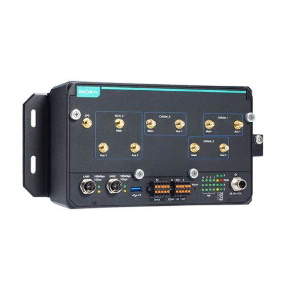
Page 10: Appearance
UC-8580 Series Hardware Hardware Introduction Appearance Front View Dimensions Unit = mm (in) -
Page 11: Led Indicators
UC-8580 Series Hardware Hardware Introduction LED Indicators LED Name Status Function Green Power is on No power input or any other power-input error Green System is ready System is booting, OS boot-up failure, or any other system initialization error Ethernet Green Steady On: 100 Mbps Ethernet link (located next to the... -
Page 12: Hardware Connection Description
Hardware Connection Description In this chapter, we show how to connect the UC-8580 computer to the network and to various devices. The following topics are covered in this chapter: Installing the UC-8580 Series Wiring Requirements Connecting the Power ... -
Page 13: Installing The Uc-8580 Series
UC-8580 Series Hardware Hardware Connection Description Installing the UC-8580 Series Wall or Cabinet Mounting Use two screws per side to mount the UC-8580 computer on to a wall or in a cabinet. Wiring Requirements Be sure to read and follow these common safety precautions before proceeding with the installation of any electronic device: •... -
Page 14: Connecting The Power
UC-8580 Series Hardware Hardware Connection Description Connecting the Power Connect the 24 to 110 VDC power line with M12 A-coded connector to the UC-8580 Series computer. If the power is supplied properly, the P LED will glow a solid green after a 25 to 30-second delay. The power input location and pin definition are shown in the following figures: Grounding the Unit Grounding and wire routing help limit the effects of noise due to electromagnetic interference (EMI). -
Page 15: Connecting Data Transmission Cables
UC-8580 Series Hardware Hardware Connection Description Connecting Data Transmission Cables In this section, we describe how to connect the UC-8580 embedded computer to a network and serial devices. Connecting to an Ethernet Network Connect your network cable to the embedded computer’s Ethernet port. The other end of the cable should be connected to your Ethernet network. -
Page 16: Connecting Digital Input/ Output Devices
UC-8580 Series Hardware Hardware Connection Description RS-232 RS-422 TxD+ TxD- RxD+ RxD- RS-485 DATA+ DATA- Connecting Digital Input/ Output Devices The UC-8580 computer comes with a 3-channel digital input and 3-channel digital output terminal block that you can use to connect your digital devices. The DI/O pin assignments and wiring methods are shown below:... -
Page 17: Connecting A Usb Device
UC-8580 Series Hardware Hardware Connection Description Connecting a USB Device The UC-8580 computer is provided with a USB 3.0 port on the front panel for connecting a USB device. Connecting Wi-Fi/Cellular Modules and Installing Antennas The UC-8580 computer is provided with four sets of antenna holes for installing antennas for the Wi-Fi and cellular modules. - Page 18 UC-8580 Series Hardware Hardware Connection Description Socket Name Usage Cellular_1 Cellular module Cellular_2 Cellular module Cellular_3 Cellular module Wi-Fi_4 Wi-Fi module You will need to install the SIM cards for the cellular modules in the designated SIM-card slots. For the cellular module in socket 1, insert SIM cards in the SIM 1-1 and SIM 1-2 slots.
- Page 19 UC-8580 Series Hardware Hardware Connection Description Follow these steps to install a wireless (Wi-Fi/cellular) module. 1. The wireless module come with the thermal pads attached. Remove the plastic protective film on the thermal pads. 2. Insert the wireless module in the designated socket and tighten the two screws on the module. 3.
- Page 20 UC-8580 Series Hardware Hardware Connection Description Refer to the following figure provided on the front panel to identify the antenna mounting holes for the wireless modules. 4. Use the black tape provided in the package to secure the antenna cables to the module and attach tags (also provided in the package) to the cables to help identify them easily as shown in the picture below: 5.
-
Page 21: Installing Sim Cards For The Cellular Modules
UC-8580 Series Hardware Hardware Connection Description 6. Plug the antennas into the connectors on the front panel. Refer to the following figure for the location of each antenna connector, including the connector for a GPS antenna. Use the procedure described above to install other Wi-Fi or cellular modules. NOTE The Wi-Fi module installed in socket 4 requires three antennas. -
Page 22: Installing The Msata Module
UC-8580 Series Hardware Hardware Connection Description 3. Push down the SIM card holder until the SIM card is secured in place. Installing the mSATA Module The UC-8580 computer is provided with one storage socket for installing an mSATA module. To install the mSATA module, do the following: Locate the mSATA socket.
Need help?
Do you have a question about the UC-8580-T-CT-LX and is the answer not in the manual?
Questions and answers