Moxa Technologies NPort W2150A-W4 Series User Manual
Hide thumbs
Also See for NPort W2150A-W4 Series:
- Quick installation manual (9 pages) ,
- Tech note (5 pages)

Related Manuals for Moxa Technologies NPort W2150A-W4 Series


Summary of Contents for Moxa Technologies NPort W2150A-W4 Series
- Page 1 NPort W2150A-W4/W2250A-W4 Series User Manual Version 1.0, January 2023 www.moxa.com/products © 2023 Moxa Inc. All rights reserved.
- Page 2 NPort W2150A-W4/W2250A-W4 Series User Manual The software described in this manual is furnished under a license agreement and may be used only in accordance with the terms of that agreement. Copyright Notice © 2023 Moxa Inc. All rights reserved. Trademarks The MOXA logo is a registered trademark of Moxa Inc.
-
Page 3: Table Of Contents
Table of Contents Introduction ............................5 Overview .............................. 5 Package Checklist ..........................5 Product Features ........................... 6 Serial Port Pin Assignments ........................6 Getting Started ............................. 7 Overview .............................. 7 Panel Layout ............................7 LED Indicators ............................8 Top Panel LED Indicators ......................... 8 End Panel LED Indicators ......................... - Page 4 Network Settings ..........................46 General Settings .......................... 46 Ethernet/Bridge Settings ....................... 47 WLAN Settings ..........................49 Advanced Settings ........................61 Web Console: Serial Port Settings....................... 62 Overview ............................62 Serial Port Settings ........................62 Communication Parameters ......................81 Data Buffering/Log ........................82 Web Console: System Management ....................
-
Page 5: Introduction
1. Introduction Overview In this chapter, we introduce the basic features and specifications of the NPort W2150A-W4/W2250A-W4 Series and NPort W2150A-W4/W2250A-W4 Series-T, referred to collectively as the NPort W2150A- W4/W2250A-W4 Series. The NPort W2150A-W4/W2250A-W4 Series of wireless device servers are used to connect RS-232/422/485 serial devices or Ethernet devices, including PLCs, meters, and sensors, to a wireless LAN. -
Page 6: Product Features
Optional Accessories • DK35A: DIN-rail mounting kit (35 mm) Power-jack-to-terminal-block 12 cable (P/N: 9199000000900) • NOTE Please notify your sales representative if any of the above items is missing or damaged. Product Features Links serial and Ethernet devices to an IEEE 802.11a/b/g/n network •... -
Page 7: Getting Started
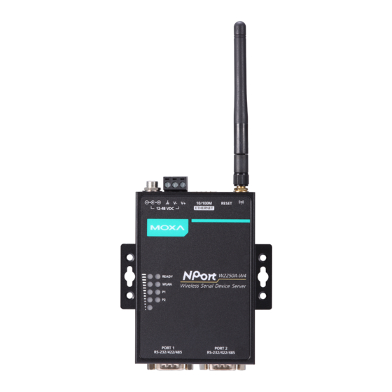
2. Getting Started Overview This chapter presents the hardware features of the NPort W2150-W4/W2250A-W4 Series and explains how to connect the hardware. Panel Layout NPort W2150A-W4/W2150A-W4-T NPort W2250A-W4/W2250A-W4-T NPort W2150A-W4/W2250A-W4 Series User Manual... -
Page 8: Led Indicators
LED Indicators Top Panel LED Indicators Name Color Function Steady on: Power is on, and the NPort is booting up. Blinking: An IP conflict exists, or the DHCP server did not respond properly. Ready Steady on: The NPort is functioning normally. Green Blinking: The unit is responding to Locate function. -
Page 9: Pull High/Low Resistors For Rs-422/485
Pull High/Low Resistors for RS-422/485 You may need to set the pull high/low resistors when termination resistors are used for certain RS-422 or RS-485 environments. S4 (Port 1) DIP 1 DIP 2 DIP 3 DIP 4 S5 (Port 2) Pull high resistor Pull low resistor Termination resistor Reserved... -
Page 10: Placement Options
Placement Options The NPort can be placed on a desktop or other horizontal surface. You can also install the NPort on a DIN- rail or on the wall. Wall Mounting DIN-Rail Mounting Connecting the Hardware ATTENTION Before connecting the hardware, follow these important wiring safety precautions: Disconnect power source Do not install or wire this unit or any attached devices with the power connected. -
Page 11: Connecting To The Network
Connecting to the Network Use the supplied Ethernet cable to connect the NPort to your Ethernet network. If the cable is properly connected, the NPort will indicate a valid connection to the Ethernet as follows: A green Ethernet LED indicates a valid connection to a 100 Mbps Ethernet network. •... -
Page 12: Initial Ip Configuration
3. Initial IP Configuration Overview This chapter presents several ways to assign the NPort’s IP address for the first time. Please refer to Chapter 2 for instructions on connecting to the network. The web console is the recommended method for configuring the NPort. Please refer to Chapter 5 and 6 for details on using the web console for configuration. - Page 13 3. Enter your login account and password, then press ENTER. (Default login is admin and password is moxa.) You will login to the Overview page. Press N or use the cursor keys to select Network and press ENTER. Press E or use the cursor keys to select Ethernet and press ENTER. NPort W2150A-W4/W2250A-W4 Series User Manual...
- Page 14 Use the cursor keys to navigate between the different fields. For IP address, Netmask, and Gateway, enter the desired values directly. For IP configuration, LAN speed, and Ethernet bridge, press ENTER to open a submenu and select between the available options. Press ESC to return to the menu.
-
Page 15: Using The Serial Console To An Assign Ip Address
Using the Serial Console to an Assign IP Address Before using the NPort’s serial console, turn off the power and use a serial cable to connect the NPort console port to your computer’s serial port. Port 1 on the NPort serves as the console port. Use Port 1 connecting to the console port with a serial-based terminal or terminal emulator program, such as Windows HyperTerminal. - Page 16 In your terminal emulator program, set the terminal type to ANSI or VT100. If you select Dumb Terminal as the terminal type, some of the console functions—especially the “Monitor” function—may not work properly. Hold the grave accent key (`) down and power up the NPort. The continuous string of grave accent characters triggers the NPort to switch from data mode to console mode.
-
Page 17: Introduction To Operation Modes
4. Introduction to Operation Modes Overview This chapter introduces the different serial port operation modes that are available on the NPort W2150A- W4/W2250A-W4 Series. Each serial port on the NPort is configured independently of the other ports, with its own serial communication parameters and operation mode. The serial port’s operation mode determines how it interacts with the network, and different modes are available to encompass a wide variety of applications and devices. -
Page 18: Rfc2217 Mode
Real COM mode allows you to continue using your serial communications software to access devices that are now attached to your NPort device server. On the host, the NPort Real COM driver automatically intercepts data sent to the COM port, packs it into a TCP/IP packet, and redirects it to the network. At the other end of the connection, the NPort device server accepts the Ethernet frame, unpacks the TCP/IP packet, and sends the serial data to the appropriate device. -
Page 19: Udp Mode
UDP Mode UDP is similar to TCP but is faster and more efficient. Data can be broadcast to or received from multiple network hosts. However, UDP does not support verification of data and would not be suitable for applications where data integrity is critical. -
Page 20: Reverse Terminal Mode
Reverse Terminal Mode Reverse terminal applications are similar to terminal applications, as they use the NPort W2x50A-W4 to manage the connection between a terminal and a server. The difference is that with reverse terminal applications; the terminal is connected through the network and the server is connected through the serial port, rather than the other way around. -
Page 21: Installing And Configuring The Software
5. Installing and Configuring the Software Overview This chapter describes how to install and use the NPort Windows Driver Manager, the Device Search Utility (DSU), and NPort Linux and UNIX drivers. You may download these items from Moxa’s website that is provided with the NPort W2150A-W4/W2250A-W4 Series. - Page 22 Select a destination location and click Next to proceed. Show if you wish to create a desktop icon and click Next to proceed. NPort W2150A-W4/W2250A-W4 Series User Manual...
-
Page 23: Finding Nport Device Servers On A Network
Verify the installation parameters and click Install to proceed. The wizard will begin installing the files. After the files have been installed, click Finish to complete the installation. Finding NPort Device Servers on a Network You can use the Device Search Utility (DSU) to look up or change the IP address of any NPort device server on the network. -
Page 24: Modifying Nport Ip Addresses
The utility will search for NPort device servers. When the search is complete, the NPort units that were found will be listed in the main window. Unlock Device Servers Select the device and click Un-Lock. Enter password and click OK. Modifying NPort IP Addresses Once the Device Search Utility (DSU) has found NPort device servers on the LAN, you can change any unit’s IP address. -
Page 25: Upgrading Nport Firmware
Enter the new IP address and netmask. If multiple units were selected, you may assign addresses sequentially by clicking Assign IP Sequentially. Click OK to proceed. The selected NPort will be restarted by the Device Search Utility (DSU) with the new IP address. Upgrading NPort Firmware Once the Device Search Utility (DSU) has found NPort device servers on the LAN, you can upgrade any unit’s firmware. - Page 26 Select the new firmware file and click OK to proceed. To get the latest firmware for the NPort W2150A- W4/W2250A-W4 Series, visit www.moxa.com. The utility will begin upgrading the firmware for the selected unit. Do not disconnect or power off the unit while the firmware is being upgraded.
-
Page 27: Nport Windows Driver Manager
NPort Windows Driver Manager NPort Windows Driver Manager installs remote NPort serial ports as new COM ports on your Windows PC. When the drivers are installed and configured, devices that are attached to serial ports on the NPort will be treated as if they were attached to your PC’s own COM ports. - Page 28 Select a destination location and click Next to proceed. Select a folder for the program shortcuts and click Next to proceed. NPort W2150A-W4/W2250A-W4 Series User Manual...
- Page 29 Verify the installation parameters and click Install to proceed. If you see a warning that the software has not passed Windows Logo testing, click Continue Anyway to proceed. NPort W2150A-W4/W2250A-W4 Series User Manual...
-
Page 30: Adding Mapped Serial Ports
The wizard will begin installing the files. When the files have been installed, click Finish to complete the installation. Adding Mapped Serial Ports NPort Windows Driver Manager adds a COM port to your PC that is mapped to an NPort serial port. The destination NPort serial port must be set to Real COM mode. - Page 31 Alternatively, you can select Input Manually and manually enter the NPort IP Address, 1st Data Port, 1st Command Port, and Total Ports for the desired NPort unit. Click OK to proceed. NPort Windows Driver Manager will list each available serial port and will automatically assign a new COM port to each one.
-
Page 32: Configuring Mapped Serial Ports
Activated COM ports will be listed in black; COM ports that have not been activated will be listed in blue. Once a COM port has been activated, the host computer will communicate with the new COM port as if it were physically attached. Since the COM mappings are stored in the host system registry, they will still be in effect if the PC is restarted or if Windows Driver Manager is closed. - Page 33 On the Basic Setting tab, select the COM Number that will be assigned to the serial port. If you have selected multiple ports, you can assign COM numbers automatically in sequential order by selecting the Auto Enumerating COM Number for Selected Ports function. On the Advanced Setting tab, configure Tx Mode, FIFO, and Fast Flush.
- Page 34 Auto Network Re-Connection: With this option enabled, the driver will repeatedly attempt to re- establish the TCP connection if the NPort does not respond to background “check-alive” packets Always Accept Open Requests: When enabled, the NPort driver will always accept requests to open a virtual COM port, even if communications with the device can not be established.
- Page 35 On the Security tab, select the Enable Data Encryption option to enable data to be encrypted when transmitted over the COM ports. After selecting the encryption option, select the Keep connection option to encrypt COM port communications immediately without restarting the COM ports. This may speed up opening and closing of the COM port for your host, but it also causes your host to tie up the NPort serial port so other hosts cannot use it.
- Page 36 To save all COM mapping settings to a text file, right-click a COM port and select Export in the context menu. After the settings have been exported to a file, they can be imported on another host. NPort W2150A-W4/W2250A-W4 Series User Manual...
-
Page 37: Command-Line Installation/Removal
Command-Line Installation/Removal For NPort Windows Driver Manager v1.19 and above, it comes with command line script tool – npcli.exe for installation, removal of the driver and capability of configuring NPort driver functions. After successfully installing NPort Windows Driver Manager v1.19 (or above), the default file path is C:\Program Files\NPortDrvManager as shown below. - Page 38 ------------------------------------------------------------------------------ NPort Command Line Interface Ver2.0 Build 16052400 ------------------------------------------------------------------------------ sage: 1. NPort Driver operation: npcli /driver [/install | /uninstall | /upgrade] [PATH_NAME] /install Install specified driver to host. /uninstall Uninstall current installed driver from host. /upgrade Upgrade specified driver without modifying the mapped ports. PATH_NAME Specify the installer file of the NPort Driver Manager to install or upgrade.
-
Page 39: Linux Real Tty Drivers
Linux Real TTY Drivers Real TTY driver are provided that will map Linux host TTY ports to NPort serial ports. Once the mapping has been set up, Linux users and applications can connect to a serial port as if it were a local TTY port. These drivers have been designed and tested for most Linux distributions, including Linux kernel version 2.4.x, 2.6.x, and 3.x, 4.x. -
Page 40: Removing Mapped Tty Ports
Mapping TTY ports automatically To map TTY ports automatically, you may execute mxaddsvr with just the IP address and number of ports, as in the following example: # cd /usr/lib/npreal2/driver # ./mxaddsvr 192.168.3.4 16 In this example, 16 TTY ports will be added, all with IP 192.168.3.4, with data ports from 950 to 965 and command ports from 966 to 981. -
Page 41: Installing The Unix Driver
Installing the UNIX Driver 1. Log in to UNIX and create a directory for the MOXA TTY. To create a directory named /usr/etc, execute the command: # mkdir –p /usr/etc Copy moxattyd.tar to the directory you created. For the /usr/etc directory, you would execute the following commands: # cp moxattyd.tar /usr/etc # cd /usr/etc... - Page 42 Adding an additional server Change the text file moxattyd.cf to add an additional server. Users may use vi or any text editor to change the file. For more configuration information, refer to moxattyd.cf, which contains detailed descriptions of the various configuration parameters. Find the process ID (PID) of the moxattyd.
-
Page 43: Web Console: Basic Settings
6. Web Console: Basic Settings Overview This chapter introduces the NPort web console and explains how to configure the basic settings. The NPort can be configured from anywhere on the network through its web console. Simply point the browser to the device server’s IP address to open the web console. Network settings, operation mode, and other items can all be configured through the browser. -
Page 44: Basic Settings
The web console will appear as shown below. Settings are presented on pages that are organized by folder. Select the desired folder in the left navigation panel to open that page. The page will be displayed in the main window on the right. Certain folders can be expanded by clicking the adjacent “–”... - Page 45 Server Name Default NPortW2150A_<serial no.> or NPortW2250A_<serial no.> Options free text (e.g., “Server 1”) Description This is an optional free text field to help you differentiate one device server from another. It does not affect operation of the NPort device server. Server Location Default Options...
-
Page 46: Web Console: Network Settings
7. Web Console: Network Settings Overview This chapter explains how to configure all settings located under the Network Settings folder in the NPort web console. Network Settings General Settings On the General Settings page in the Network Settings folder, you can change DNS server 1 and 2. DNS Server 1 and 2 Default Options... -
Page 47: Ethernet/Bridge Settings
Ethernet/Bridge Settings To enable the Ethernet-to-Wireless function, also called Wireless Client, go to the Ethernet/Bridge Settings page and enable Ethernet Bridge. When it's enabled, the LAN and WLAN will use the same IP configuration (use the same IP address, netmask and gateway settings). ATTENTION In dynamic IP environments, the NPort will send three requests every 30 seconds to the DHCP server until the network settings have successfully been assigned. - Page 48 IP Configuration Default Static Options Static, DHCP Description This field determines how the NPort’s IP address will be assigned. Static: IP address, netmask, and gateway are user-defined. DHCP: IP address, netmask, gateway, DNS, and time server are assigned by the DHCP server.
-
Page 49: Wlan Settings
WLAN Settings WLAN The WLAN page is located under WLAN Settings in the Network Settings folder. You can modify IP configuration, IP address, Netmask, and Gateway for your WLAN. The NPort W2150A-W4/W2250A-W4 Series supports IEEE 802.11a/b/g/n wireless network interfaces. The supported IP configurations are static and dynamic (DHCP). - Page 50 Netmask Default 255.255.255.0 Options Netmask setting (e.g., “255.255.0.0”) Description This field is for the subnet mask. A subnet mask represents all the network hosts at one geographic location, in one building, or on the same LAN. When a packet is sent out over the network, the NPort device server will use the subnet mask to check whether the desired TCP/IP host specified in the packet is on the local network segment.
- Page 51 The Profile page is located under WLAN Settings in the Network Settings folder. This is where you configure the NPort for Infrastructure operation. Network Type Default Infrastructure Mode Options Infrastructure Mode Description The NPorts in Infrastructure Mode do not communicate directly with each other, but through a wireless access point (AP).
- Page 52 On the General page, you can configure Profile name, RF type, and input an SSID provided by your Wi-Fi AP. Additional settings are also available. Profile Name Default Infrastructure (in Infrastructure Mode) Options free text (e.g., “Primary Connection”) Description This is a free text field to help you differentiate one profile from another. It does not affect operation of the NPort.
- Page 53 Site Survey When you click Site Survey, the device server will scan for all the APs it can find nearby. It shows all the signal strengths between the device server and the APs. You may check the checkbox and click OK to create a profile for the specified AP.
- Page 54 Roaming threshold Default -70 (Disable) Options numbers Description When the signal strength between the device and the AP is worse than this number, below -70 dBm as the default number, the device server will scan for a new AP to establish the connection.
- Page 55 Authentication Default Open System Options Open System, Shared Key, WPA, WPA-PSK, WPA2, WPA2-PSK Description This field specifies how wireless devices will be authenticated. Only authenticated devices will be allowed to communicate with the NPort. If a RADIUS server is used, this setting must match the setting on the RADIUS server.
- Page 56 Encryption Default Disable Options Disable, WEP, TKIP, AES-CCMP Description This field specifies the type of encryption to use during wireless communication. Different encryption methods are available depending on the Authentication setting. Also, each encryption method has its own set of parameters that may also require configuration. Disable: No encryption applies to the data during wireless communication.
- Page 57 Security Settings for WEP Encryption When Encryption is set to WEP on the Security page for the WLAN profile, you will configure WEP key length, WEP key index, and WEP key source. It will display other settings, depending on how WEP key source is configured.
- Page 58 WEP Key 1 Through 4 Default Options free text in ASCII or HEX Description These fields are only available if WEP key source is set to Manual. Enter each WEP key in ASCII or HEX as specified in WEP key format. The number of characters required for each key depends on WEP key length and WEP key format.
- Page 59 There are two parts to WPA and WPA2 security, authentication, and data encryption. • Authentication occurs before access is granted to a WLAN. Wireless clients such as the NPort W2150A- W4/W2250A-W4 Series are first authenticated by the AP according to the authentication protocol used by the RADIUS server.
- Page 60 Password Default Options free text (e.g., “Password123”) Description This field specifies the password that will gain access to the WLAN. The correct username and password must be provided for access to be granted. Anonymous Username Default Options free text (e.g., “Anyuser”) Description This field specifies the anonymous username to use when starting authentication.
-
Page 61: Advanced Settings
WLAN Log Settings Default Disable Options Disable, Enable Description When the wireless connection between the device server and the AP is not stable, you may enable this function to have more information for troubleshooting. You may find System Monitoring System Status WLAN Log for the detail logs. Before calling for help from Moxa, please enable this function to collect some information. -
Page 62: Web Console: Serial Port Settings
8. Web Console: Serial Port Settings Overview This chapter explains how to configure all settings located under the Serial Port Settings folder in the NPort web console. Serial Port Settings Operation Modes Each serial port on the NPort is configured through the hyperlink below the column of Operating mode. Click the link of Real COM. - Page 63 Operation Mode Default Real COM Options Real COM, RFC2217, TCP Server, TCP Client, UDP, Pair_Master, Pair_Slave, EModem Description Along with Application, this field specifies the serial port’s operation mode, or how it will interact with network devices. Depending on how Application is configured, different options are available for Mode.
- Page 64 Settings for Real COM Mode When Operation Mode is set to Real COM on a serial port’s Operation Modes page, you will configure additional settings including TCP alive check time, Max connection, Ignore jammed IP, Allow driver Control, Connection goes down, Packet length, Delimiter 1, Delimiter 2, Delimiter process, and Force transmit.
- Page 65 ATTENTION When Max connection is two or greater, the serial port’s communication settings (i.e., baudrate, parity, data bits, etc.) will be determined by the NPort. Any host that opens the COM port connection must use identical serial communication settings. Ignore jammed IP Default Disable Options...
- Page 66 Delimiter 1 and 2 Default Disabled Options Disabled, Enabled, 00 to FF Description These fields are used to define special delimiter character(s) for data packing. Enable Delimiter 1 to control data packing with a single character; enable both Delimiter 1 and 2 to control data packing with two characters received in sequence.
- Page 67 Settings for RFC2217 Mode When Operation Mode is set to RFC2217 on a serial port’s Operation Modes page, you will configure additional settings, including TCP alive check time, TCP port, Packet length, Delimiter 1, Delimiter 2, Delimiter process, and Force transmit. TCP alive check time Default 7 min...
- Page 68 Delimiter 1 and 2 Default Disabled Options Disabled, Enabled, 00 to FF Description These fields are used to define special delimiter character(s) for data packing. Enable Delimiter 1 to control data packing with a single character; enable both Delimiter 1 and 2 to control data packing with two characters received in sequence.
- Page 69 Settings for TCP Server Mode When Operation Mode is set to TCP Server on a serial port’s Operation Modes page, configure additional settings such as TCP alive check time, Inactivity time, Max connection, Ignore jammed IP, Allow driver control, TCP port, Cmd port, Connection goes down, Packet length, Delimiter 1, Delimiter 2, Delimiter process, and Force transmit.
- Page 70 Max connection Default Options 1 to 8 Description This field specifies the maximum number of connections that the serial will accept port. 1: Only one specific host can access this serial port, and the Real COM driver on that host will have full control over the port.
- Page 71 IP Serial Library Introduction What is IP Serial Library? IP Serial Library is a Windows library with frequently used serial command sets and subroutines. IP Serial Library reduces the complexity and poor efficiency of serial communication over TCP/IP. For example, Telnet can only transfer data, but it can't monitor or configure the serial line's parameters.
- Page 72 ATTENTION When Delimiter 1 is enabled, Packet length must be set to 0. Delimiter process Default Do Nothing Options Do Nothing, Delimiter + 1, Delimiter + 2, Strip Delimiter Description This field specifies how data is packed when delimiter characters are received. This field has no effect if Delimiter 1 is not enabled.
- Page 73 Settings for TCP Client Mode When Operation Mode is set to TCP Client on a serial port’s Operation Modes page, you will be able to configure additional settings such as TCP alive check time, Inactivity time, Ignore jammed IP , Destination address 1-4, Designated local port 1-4, Connection control, and Packet length, Delimiter 1, Delimiter 2, Delimiter process, and Force transmit.
- Page 74 Ignore jammed IP Default Disable Options Disable, Enable Description This field specifies how an unresponsive IP address is handled when there are simultaneous connections to the serial port. Disable: All transmission will be suspended if one IP address becomes unresponsive. Transmission will only resume when all hosts have responded.
- Page 75 Packet length Default Options 0 to 1024 Description This field specifies the maximum amount of data that is allowed to accumulate in the serial port buffer before sending. 0: Packet length is disregarded and data in the buffer will be sent as specified by the delimiter settings or when the buffer is full.
- Page 76 Force transmit Default 0 ms Options 0 to 65535 Description This field controls data packing by the amount of time that elapses between bits of data. When using this field, make sure that Inactivity time is disabled or set to a larger value. Otherwise the connection may be closed before the data in the buffer can be transmitted.
- Page 77 Local listen port Default 4001 Options Description This field specifies the UDP port that the NPort listens to and that other devices must use to contact the attached serial device. Packet length Default Options 0 to 1024 Description This field specifies the maximum amount of data that is allowed to accumulate in the serial port buffer before sending.
- Page 78 Force transmit Default 0 ms Options 0 to 65535 Description This field controls data packing by the amount of time that elapses between bits of data. When using this field, make sure that Inactivity time is disabled or set to a larger value. Otherwise the connection may be closed before the data in the buffer can be transmitted.
- Page 79 TCP alive check time Default 7 min Options 0 to 99 min Description This field specifies how long the NPort will wait for a response to “keep-alive” packets before closing the TCP connection. The NPort checks connection status by sending periodic “keep-alive”...
- Page 80 TCP alive check time Default 7 min Options 0 to 99 min Description This field specifies how long the NPort will wait for a response to “keep-alive” packets before closing the TCP connection. The NPort checks connection status by sending periodic “keep-alive”...
-
Page 81: Communication Parameters
Try next type on authentication denied (default=Disable): This field enables or disables the system to try the next type if the first authentication is denied. Map keys <CR-LF> (default=CR-LF): This specifies how the ENTER key is mapped from the Ethernet port through the serial port. -
Page 82: Data Buffering/Log
Data bit Default Options 5, 6, 7, 8 Description This field specifies the number of data bits used to encode each character of data. Stop bit Default Options 1, 1.5, 2 Description This field specifies the number of stop bits used for each character frame. Flow control Default RTS/CTS... - Page 83 Serial data logging(64K) Default Disable Options Enable, Disable Description This field specifies whether data logs for the serial port will be stored on system RAM. Each serial port is allotted 64 KB for data logging. The data log is not saved when the NPort is powered off.
-
Page 84: Web Console: System Management
9. Web Console: System Management Overview This chapter explains how to configure all settings located under the System Management folder in the NPort web console. System Management Misc. Network Settings Accessible IP List The Accessible IP List page is located under Misc. Network Settings in the System Management folder. - Page 85 Refer to the following table for more configuration examples. Desired IP Range IP Address Field Netmask Field Any host Disable Disable 192.168.1.120 192.168.1.120 255.255.255.255 192.168.1.1 to 192.168.1.254 192.168.1.0 255.255.255.0 192.168.0.1 to 192.168.255.254 192.168.0.0 255.255.0.0 192.168.1.1 to 192.168.1.126 192.168.1.0 255.255.255.128 192.168.1.129 to 192.168.1.254 192.168.1.128 255.255.255.128 SNMP Agent Settings...
- Page 86 Read Community String Default public Options free text (e.g., “public community”) Description This field specifies the read community string used for the SNMP Agent. This is a text password mechanism that is used to weakly authenticate queries to agents of managed network devices.
- Page 87 Read/Write Privacy mode Default Disable Options Disable, DES, AES Description This field specifies whether data encryption will be used during read/write access. Read/Write Privacy Default Options free text (e.g., “read write key”) Description This field specifies the encryption key for read/write access, if read-/write privacy is enabled.
-
Page 88: Auto Warning Settings
System Log Settings The System Log page is located under Misc. Network Settings in the System Management folder. This is where you select the type of events that will be logged by the NPort. Group Event System System Cold Start, System Warm Start Network DHCP, Get IP/Renew, Mail Fail, NTP Connect Fail, IP Conflict, Network Link Down Login Fail, IP Changed, Password Changed, Firmware Upgrade, SSL Certificate Import,... - Page 89 Event Description Cold start The NPort was powered on, or was restarted after a firmware upgrade. Warm start The NPort restarted without powering off. An attempt has been made to open the web, Telnet, or serial console, but the Console login auth fail password was incorrect.
- Page 90 The E-mail Alert page is located under Auto Warning Settings in the System Management folder. This is where you specify how and where e-mail is sent when e-mail is used for automatic notification of system and serial port events. ATTENTION Consult your network administrator or ISP for the mail server settings to use for your network.
-
Page 91: Maintenance
Trap Community Default Options free text (e.g., “public access”) Description This field specifies the SNMP trap community. Maintenance Console Settings The Console Settings page is located under Maintenance in the System Management folder. This is where you enable or disable access to the various NPort configuration consoles, as well as the behavior of the reset button. - Page 92 Reset Button Default Always Enable Options Always Enable, Disable after 60 sec Description This field specifies the behavior of the hardware reset button. Always Enable: The reset button will be operated as usual. Disable after 60 sec: The reset button will only be effective for the first 60 seconds that the NPort is powered on.
- Page 93 Configuration Import The Configuration Import page is located under Maintenance in the System Management folder. This is where you can load a previously saved or exported configuration. Select or browse for the configuration file in the Select configuration file field. If you also wish to import the IP configuration (i.e., IP address, netmask, and gateway), make sure that Import all configurations including IP configurations is checked.
- Page 94 Configuration Export The Configuration Export page is located under Maintenance in the System Management folder. This is where you can save the NPort’s current configuration to a file on the local host. Click [Download] to begin the process. A window should appear asking you to open or save the configuration text file. Load Factory Default The Load Factory Default page is located under Maintenance in the System Management folder.
-
Page 95: Certificate
Change Password The Change Password page is located under Maintenance in the System Management folder. To change the password, choose the account name first, and then enter the old password in the Old password field. Enter the new password twice, once in the New password field and once in the Confirm password. Leave these fields blank to remove password protection. - Page 96 Select SSL certificate/key file field. The NPort only supports the PEM format of the certificate so far. If your file is in another format, for example DER or PFX, please convert it to PEM first. WLAN SSL Certificate Import The WLAN SSL Certificate Import page is located under Certificate in the System Management folder. By default, the WLAN SSL certificate is automatically generated by the NPort based on the IP address of the wireless interface.
- Page 97 WPA User Certificate Import The WPA User Certificate Import page is located under Certificate in the System Management folder. This is where you can load the WPA user certificate. Select or browse for the certificate file in the Select WPA user certificate file field. The user certificate of the NPort must be installed in the RADIUS server when the NPort uses WPA (WPA2)/TLS.
- Page 98 Certificate/Key Delete The Certificate/Key Delete page is located under Certificate in the System Management folder. This page is where you can delete certificates or WPA keys that have been installed on the model. When you click [Submit], any certificate or key that has been set to Delete will be deleted from the NPort. NPort W2150A-W4/W2250A-W4 Series User Manual...
-
Page 99: Web Console: System Monitoring
Web Console: System Monitoring Overview This chapter explains how to use the System Monitoring functions on the NPort web console. These functions allow you to monitor many aspects of your operation. System Monitoring Serial Status Serial to Network Connections The Serial to Network Connections page is located under Serial Status in the System Monitoring folder. - Page 100 Serial Port Status The Serial Port Status page is located under Serial Status in the System Monitoring folder. On this page, you can monitor the signal and data transmission status for each serial port. TxCnt: number of Tx packets (to device) for the current connection RxCnt: number of Rx packets (from device) for the current connection TxTotalCnt: number of Tx packets since the NPort was powered on RxTotalCnt: number of Rx packets since the NPort was powered on...
-
Page 101: System Status
Serial Port Settings The Serial Port Settings page is located under Serial Status in the System Monitoring folder. On this page, you can view the current communication settings for each serial port. System Status Network Connections The Network Connections page is located under System Status in the System Monitoring folder. On this page, you can view the status of any network connection to the NPort. - Page 102 Serial Data Log Data logs for each serial port can be viewed in ASCII or HEX format. After selecting the serial port and format, you may click Select all to select the entire log if you wish to copy and paste the contents into a text file.
- Page 103 WLAN Log The WLAN Log page is located under System Status in the System Monitoring folder. This is where you can view the log between the device server and the access points. It's an excellent tool for an engineer to troubleshoot if there is any issue with the wireless connection.
- Page 104 The WLAN Status page is located under System Status in the System Monitoring folder. This is where you can view the current WLAN settings and status. NPort W2150A-W4/W2250A-W4 Series User Manual...
-
Page 105: Web Console: Restart
Web Console: Restart Overview This chapter explains how to use save your configuration changes and restart the NPort using the NPort web console. Configuration changes will not be effective until they are saved, and the NPort is rebooted. Restart Restart System The Restart System page is in the Restart folder. -
Page 106: Android Api Instructions
Android API Instructions Overview If you want to remote control your serial devices on an Android platform, then the MxNPortAPI is a simple application programming tool you can use. The MxNPortAPI helps programmers develop an Android application to access the device server by TCP/IP. The MxNPortAPI provides frequently used serial command sets like port control, input/output, etc., and the style of developed Android application is similar to MOXA Driver Manager. -
Page 107: How To Start Mxnportapi
How to Start MxNPortAPI You can download the MxNPortAPI from Moxa’s website at http://www.moxa.com, and develop the application program in popular OSs, such as Windows, Linux, or Mac. (You can refer the Android studio website to see the system requirements for development environment: https://developer.android.com/studio/index.html?hl=zh-tw#Requirements). -
Page 108: Mxnportapi Function Groups
MxNPortAPI Function Groups The supported functions in this API are listed below: Port Control Input/Output Port Status Inquiry Miscellaneous open close getBaud setIoctlMode getFlowCtrl setFlowCtrl read getIoctlMode setBreak setBaud write getLineStatus setRTS getModemStatus setDTR getOQueue flush Example Program To make sure this API is workable with the device server on an Android platform, see the example program below: Thread thread = new Thread() @Override... -
Page 109: Snmp Agents With Mib Ii & Rs-232-Like Groups
A. SNMP Agents with MIB II & RS-232- Like Groups The NPort has built-in SNMP (Simple Network Management Protocol) agent software that supports SNMP Trap, RFC1317 RS-232 like groups and RFC 1213 MIB-II. The following table lists the standard MIB-II groups, as well as the variable implementation for the NPort. -
Page 110: Icmp Mib
ICMP MIB IcmpInMsgs IcmpInTimestamps IcmpOutRedirects IcmpInErrors IcmpTimest ampReps IcmpOutEchos IcmpInDestUnreachs IcmpInAddrMasks IcmpOutEchoReps IcmpInTimeExcds IcmpOutMsgs IcmpOutTimestamps IcmpInParmProbs IcmpOutErrors IcmpOutTimestampReps IcmpInSrcQuenchs IcmpOutDestUnreachs IcmpOutAddrMasks IcmpInRedirects IcmpOutTimeExcds IcmpOutAddrMaskReps IcmpInEchos IcmpOutParmProbs IcmpInEchoReps IcmpOutSrcQuenchs UDP MIB UdpInDatagrams UdpOutDatagrams UdpNoPorts UdpLocalAddress UdpInErrors UdpLocalPort Address Translation AtIfIndex AtNetAddress AtPhysAddress TCP MIB tcpRtoAlgorithm... -
Page 111: Rfc1317: Rs-232 Mib Objects
RFC1317: RS-232 MIB Objects Generic RS-232-like Group rs232Number RS-232-like General Port Table rs232PortTable rs232PortEntry rs232PortIndex rs232PortType rs232PortInSigNumber rs232PortOutSigNumber rs232PortInSpeed rs232PortOutSpeed RS-232-like Asynchronous Port Group rs232AsyncPortTable rs232AsyncPortIndex rs232AsyncPortStopBits rs232AsyncPortEntry rs232AsyncPortBits rs232AsyncPortParity The Input Signal Table rs232InSigTable rs232InSigPortIndex rs232InSigState rs232InSigEntry rs232InSigName The Output Signal Table rs232OutSigTable rs232OutSigPortIndex rs232OutSigState... -
Page 112: Well-Known Port Numbers
B. Well-known Port Numbers Listed below are Well-known Port Numbers that may cause network problems if they are assigned to an NPort serial port. Refer to RFC 1700 for Well-known Port Numbers or refer to the following introduction from IANA. The port numbers are divided into three ranges: Well-known Ports, Registered Ports, and Dynamic and/or Private Ports. - Page 113 UDP Socket Application Service reserved Management Utility Echo Discard Active Users (systat) Daytime Any private printer server Resource Location Protocol Host name server (names server) Whois (nickname) Login Host Protocol (Login) Domain Name Server (domain) Trivial Transfer Protocol (TETP) Gopher Protocol Finger Protocol World Wide Web HTTP Remote Telnet Service...
-
Page 114: Ethernet Modem Commands
C. Ethernet Modem Commands A serial port on the NPort can be set to Ethernet Modem mode, allowing a PC or device to connect to the NPort as if it was an Ethernet modem. This section provides additional detail about how the NPort operates in Ethernet Modem mode. -
Page 115: At Commands
AT Commands Ethernet Modem mode supports the following common AT commands, as used with a typical modem: Command Description Remarks Answer manually Dial up specified IP address and port number ATD 192.168.1.1:950 (example) ATE0=Echo OFF ATE1=Echo ON (default) ATH0=On-hook (default) ATH1=Off-hook ATI, ATI0, Modem version... -
Page 116: S Registers
S Registers Register Description Remarks Ring to auto-answer (default=0) Ring counter (always=0) no action applied Escape code character (default=43 ASCII “+”) Return character (default=13 ASCII) Line feed character (default=10 ASCII) Backspace character (default= 8 ASCII) Wait time for dial tone (always=2, unit=sec) no action applied Wait time for carrier (default=3, unit=sec) Pause time for dial delay (always=2, unit=sec)
Need help?
Do you have a question about the NPort W2150A-W4 Series and is the answer not in the manual?
Questions and answers