
Related Manuals for Raymarine LIGHTHOUSE SPORT 3.18


Summary of Contents for Raymarine LIGHTHOUSE SPORT 3.18
- Page 1 LIGHTHOUSE SPORT 3.18 ELEMENT DISPLAY OPERATING SYSTEM OPERATION INSTRUCTIONS English (en-US) Date: 12-2022 Document number: 81388 (Rev 10) © 2022 Raymarine UK Limited...
- Page 3 Please check the website to ensure you have the latest documentation. Publication copyright Copyright ©2022 Raymarine UK Ltd. All rights reserved. No parts of this material may be copied, translated, or transmitted (in any medium) without the prior written permission of Raymarine UK Ltd.
-
Page 5: Table Of Contents
CONTENTS CHAPTER 1 IMPORTANT INFORMATION ......10 Startup wizard ..............23 Electronic chart data ..............11 First power up Limitation on Use End-User License Agreements (EULAs) ......11 acknowledgement ............24 Open source license agreements ........11 Identifying engines ............24 Warranty registration ............... 11 Sonar transducer calibration ........ - Page 6 ................49 display ..................35 Units of measure ..............49 Connecting an iOS device to the display ....35 Raymarine app CHAPTER 6 WAYPOINTS, ROUTES AND TRACKS ..51 ..............36 Waypoints Pairing a Quantum™ radar scanner ................52 ......38 Placing a waypoint (Quick method) ......
- Page 7 Placing a waypoint (Detailed method) Automatic Identification System (AIS) ....52 support ..................73 Moving a waypoint ............53 AIS target context menu ..........74 Waypoint management ..........54 AIS dangerous targets ...........74 Waypoint sharing ............56 AIS vectors .................74 Routes ..................57 AIS targets list ..............75 Creating a Route ..............57...
- Page 8 SonarChart™ Live Depth offset 7.10 ............. 90 ..............104 Configuring transducer settings Enabling SonarChart Live ......104 ..........90 Fishfinder settings menu ..........105 CHAPTER 8 FISHFINDER APP..........92 CHAPTER 9 DASHBOARD APP ........... 110 Sonar technologies ............93 Dashboard app overview ..........
- Page 9 Radar app controls CHAPTER 12 TECHNICAL SUPPORT........141 ............121 Raymarine product support and servicing Radar app context menu 12.1 .... 142 ..........122 Radar modes 10.4 ..............122 Identify display variant and software Automatic Identification System (AIS) 10.5 version ................143 support ..................
-
Page 10: Chapter 1 Important Information
Off and the route or route leg MUST be built skill when operating this or any other Raymarine product. manually, ensuring compliance to the rules laid out in the above regulations. -
Page 11: Electronic Chart Data
Electronic chart data Technical accuracy Raymarine does not warrant the accuracy of such information, and is To the best of our knowledge, the information in this document was correct not responsible for damages or injuries caused by errors in chart data at the time it was produced. -
Page 12: Chapter 2 Document And Product Information
CHAPTER 2: DOCUMENT AND PRODUCT INFORMATION CHAPTER CONTENTS • 2.1 Product documentation — page 13... -
Page 13: Product Documentation
2.1 Product documentation The following documentation is applicable to your product: All documents are available to download in PDF format from the Raymarine website www.raymarine.com. Description Part number LightHouse Sport Basic operation 81384 instructions LightHouse Sport Advanced 81388 operation instructions (This... -
Page 14: User Manuals Print Shop
• Raymarine user manuals are also available to download free-of-charge from the Raymarine® website, in the popular PDF format. These PDF files can be viewed on a PC / laptop, tablet, smartphone, or on the latest... -
Page 15: Chapter 3 General Information
CHAPTER 3: GENERAL INFORMATION CHAPTER CONTENTS • 3.1 Document conventions — page 16 • 3.2 Databoxes — page 16 • 3.3 Menu types — page 19 General information... -
Page 16: Document Conventions
3.1 Document conventions Example (Chart databoxes) The following conventions are used throughout this document: • Highlight — The term ‘highlight’ refers to using the [Directional pad] to highlight an item. • Select — The term ‘select’ refers to using the [Directional pad] to highlight an item, and then pressing the [OK] button to select the item. -
Page 17: Editing Databoxes
Editing databoxes Data items The following data items can be displayed in Databoxes. Note: Where more than 1 data source is available for a data item, based on the specified Boat details ([Homescreen > Settings > Boat details]), then data items will be available for each data source. - Page 18 Category Data item Category Data item [Engine] • Engine hours [Fuel] [Tank 1] and [Tank 2]: • Engine RPM (Revolutions per minute) • [Port engine] • [Tank 1] • Fuel level (%) • Boost pressure • [Starboard engine] • [Tank 2] [All Tanks] : •...
-
Page 19: Menu Types
Category Data item Category Data item [Navigation] • Route ETA (Route Estimated Time of Arrival) • True wind speed • Route TTG (Route Time To Go) • Minimum app wind angle • Active waypoint • Maximum app wind angle • Waypoint TTG •... -
Page 20: Controls And Settings
Controls and settings Menu pages and tabs Common menu controls and options are detailed below. • Menu pages are accessed from app menu options and icons on the homescreen. Toggle switch • Menu pages are fullscreen pages • Toggle switches are used to enable (switch on) or disable containing menu options and settings, (switch off) various features and settings. -
Page 21: Chapter 4 Set Up
CHAPTER 4: SET UP CHAPTER CONTENTS • 4.1 Display controls — page 22 • 4.2 Getting started — page 23 • 4.3 Shortcuts — page 26 • 4.4 Memory card compatibility — page 27 • 4.5 Software updates — page 29 •... -
Page 22: Display Controls
4.1 Display controls 5. [Back] • Return to previous menu or dialog. The buttons available on Element™ displays and their function are detailed below. 6. [OK] — Confirms menu selections, opens context menus • Press to confirm a currently highlighted option. •... -
Page 23: Switching Active App
4.2 Getting started When the breaker is switched back on or the power cable is reconnected the display will remain powered off, until switched back on using the [Power] button. Startup wizard The first time the display is powered up, or after a [Factory reset] the startup Switching active app wizard is displayed. -
Page 24: First Power Up Limitation On Use Acknowledgement
First power up Limitation on Use acknowledgement Important: After you have completed the Startup wizard the Limitation on Use (LoU) – Ensure you select the correct [Sonar transducer]. disclaimer is displayed. – Ensure that the [Radar installed] option is enabled if you intend to connect a Quantum™... -
Page 25: Sonar Transducer Calibration
Sonar transducer calibration Sonar transducers should be calibrated to ensure accurate readings are displayed on the MFD. Depth offset Depths are measured from the transducer face to the bottom (e.g.: seabed). An offset value can be applied to the depth data so that the displayed depth reading represents the depth reading taken from either the keel (negative offset) or the waterline (positive offset). -
Page 26: Performing A Settings Or Factory Reset
4.3 Shortcuts Performing a settings or factory reset Performing a [Factory reset] will erase ALL user data and reset the display’s The Shortcuts menu can be accessed by pressing the [Power] button. settings to their Factory default values. Performing a [Settings reset] will restore your display’s settings to factory defaults, whilst retaining user data. -
Page 27: Adjusting Brightness
2. Press the [Power ] button. 1. Select [Color theme:] The Shortcuts menu is displayed. The pop-over menu with available color themes is displayed. 3. Select [Take screenshot]. 2. Select the desired color theme. The screenshot will be saved in .png format to the inserted memory card. Note: Note: Changing the [Color theme] inverts the Black and White colors used for... -
Page 28: Removing Microsd Card From Its Adaptor
Inserting a MicroSD card Display Native card supported Type Size format Format MicroSDSC (Micro Up to 4GB FAT12, FAT16 NTFS, Secure Digital or FAT16B FAT32, Standard Capacity) exFAT MicroSDHC (Micro 4GB to 32GB FAT32 NTFS, Secure Digital High FAT32, Capacity) exFAT MicroSDXC (Micro 32GB to 2TB... -
Page 29: Software Updates
Identifying connected products To display a list of products that are connected to the same SeaTalkng ® Raymarine® regularly issues software updates for its products which provide backbone follow the steps below. new and enhanced features and improved performance and usability. -
Page 30: Updating Display Software Using A Memory Card
1. Check the product hardware variant and the software version of the products you want to update. Note: 2. Go to the Raymarine website: ([www.raymarine.com > Support > Software • Your products may reboot automatically as part of the update process. Updates]). -
Page 31: User Data Import And Export
[Homescreen > Settings > Import/export]. 5. Select [OK] to return to the Import/export menu, or select [Eject card] to safely remove the memory card. The user data file is saved to the ‘\Raymarine\My Data\’ directory of your memory card in gpx format. Set up... -
Page 32: Importing User Data
Importing user data Manually adjusting an EV-1 heading sensor You can import user data (i.e.: GPX format Waypoints, Routes and Tracks) If there is a difference between Heading and the reported COG (Course Over to your display. Ground), which is not attributable to tide and wind conditions, then you can adjust the EV-1 heading sensor’s settings to compensate. -
Page 33: Locking Compass Calibration
If you prefer, you can manually select your own source for the data. MDS is a Raymarine scheme for managing multiple sources of identical data The [Data sources] menu can be accessed from the [Settings] menu: types on the same network (e.g.: in an MFD network you may have more than... -
Page 34: Manually Assigning A Data Source
Mobile devices can be connected to the display using a Wi-Fi connection. 1. Select [Settings]. Connecting your mobile device to the display enables the use of Raymarine 2. Select the [This display] tab. apps e.g.: RayConnect. The credentials for your display’s Wi-Fi connection 3. -
Page 35: Connecting An Android Device To The Display
passphrase page. The passphrase can also be changed from the same 3. When your Android device is connected to your MFD’s Wi-Fi it will display page. connected under the MFD’s name. The display’s Wi-Fi network channel can be viewed from the Wi-Fi For troubleshooting advice refer to the Wi-Fi troubleshooting information on settings tab and can be changed by selecting the channel field. -
Page 36: Raymarine App
Follow the steps below to use the Raymarine app: Log in with an existing Raymarine account or create one using the app. 2. Purchase LightHouse™ Charts with the Chart Store. 3. Define the regions and types of cartographic data you want the chart to contain. - Page 37 • A file named ‘Lighthouse_charts’ must be created in the memory card’s root directory (Chart cards purchased from the Raymarine chart store will 1. Install and open the Raymarine app from the relevant app store, using the already include this file).
-
Page 38: Pairing A Quantum™ Radar Scanner
Pairing a Quantum™ radar scanner You can connect a Quantum™ radar scanner to your display using the Wi-Fi connection. Pre-requisites: • Ensure you have installed and connected your Quantum™ radar scanner to a power supply following the instructions supplied with the radar scanner. •... -
Page 39: Chapter 5 Homescreen
CHAPTER 5: HOMESCREEN CHAPTER CONTENTS • 5.1 Homescreen overview — page 40 • 5.2 Customizing app pages — page 43 • 5.3 Creating a new app page — page 43 • 5.4 Global positioning — page 44 • 5.5 Status area — page 45 •... -
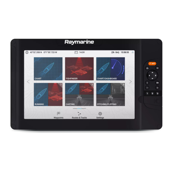
Page 40: Homescreen Overview
5.1 Homescreen overview changes. You can identify which Homescreen page is being shown using the indicator bar, located above the [Routes & Tracks] icon. All settings and apps can be accessed from the Homescreen. 5. Waypoints — Select to view the [Waypoints] list. 6. - Page 41 [Chart] — The Chart app displays electronic cartographic information from your Chart cards and when used in [Radar] — The Radar app is a situational awareness aid that conjunction with a GNSS (GPS) receiver, plots your vessel’s displays a graphical representation of your surroundings in position.
-
Page 42: Assigning App Pages To Quicklaunch Buttons
SideVision™ Radial The SideVision™ fishfinder channel is represented using the The radial app page is a fullscreen page that provides an SideVision™ app icon. instantaneous (real-time), radial view of the water beneath The SideVision™ fishfinder channel provides a photo like the transducer. -
Page 43: Customizing App
5.2 Customizing app pages 5.3 Creating a new app page You can customize the homescreen app pages. The homescreen consists of 3 homescreen pages, the first page is populated with app page icons by default. New pre-configured app pages can be 1. -
Page 44: Global Positioning
5.4 Global positioning GPS / GNSS settings Settings for your GPS / GNSS receiver can be accessed by selecting the top GPS/GNSS status left corner of the homescreen and then selecting the [Settings] tab. Your vessel’s GPS/GNSS position coordinates are provided in the top left corner of the homescreen. -
Page 45: Status Area
5.5 Status area 5.6 Timer The status area is located at the top right of the homescreen. This area displays the current time and identifies the status of the display’s sonar ping. The status area pop-over menu provides access to the timer and time and date settings. -
Page 46: Alarms
5.7 Alarms Acknowledging alarms Follow the steps below to acknowledge an active alarm. Alarms are used to alert you to a hazard or situation requiring your attention. Alarms are triggered based on their specified thresholds. With an alarms notification displayed onscreen: 1. -
Page 47: Ais Dangerous Targets
• [Low voltage] If enabled, the alarm is triggered if the supply voltage to the display drops below the value specified in the [Low voltage threshold ]field. • [Off track] — If enabled, during active navigation an alarm is triggered when your vessel steers off track by more than the specified [Cross track error] value. -
Page 48: Selecting Display Language
Settings Settings [Getting • Hardware and software information about your display. [Import/ex- • Import and export user data (Waypoints, Routes and started] port] Tracks) from MicroSD card. • Update display software. • Eject SD card. • Change the user interface language. [Wi-Fi] •... -
Page 49: Boat Details
Boat details Option Description To ensure correct operation and display of data you should set the Boat [Black water You can configure your system to display data for a Details settings according to your requirements. tanks:] Black water tank. Boat details can be accessed from the [Settings] menu: [Homescreen > [Batteries:] You can configure your system to display data for up to Settings >... - Page 50 Measurement Units Measurement Units [Temperature units] • [Celsius] — C [Variation:] • Auto • [Fahrenheit] — F • Manual [Wind speed units] • [Knots] — kts [Manual variation:] • 30°W to 30°E • [Meters per Second] — m/s [Volume units] •...
-
Page 51: Chapter 6 Waypoints, Routes And Tracks
CHAPTER 6: WAYPOINTS, ROUTES AND TRACKS CHAPTER CONTENTS • 6.1 Waypoints — page 52 • 6.2 Routes — page 57 • 6.3 Tracks — page 61 • 6.4 User data import and export — page 63 Waypoints, Routes and Tracks... -
Page 52: Waypoints
6.1 Waypoints Placing a waypoint at your vessel's location To place a waypoint at your vessel’s locations follow the steps below. Waypoints are used to mark specific locations or points of interest. Note: Waypoints can be used in the Chart and Fishfinder apps. Your display can For a waypoint to be placed at your vessel’s location your display must store up to 5,000 waypoints, which can be sorted in up to 200 waypoint have a GPS/GNSS position fix. -
Page 53: Moving A Waypoint
Note: Selecting [Delete] will delete the waypoint. Moving a waypoint You can move an existing waypoint to a new location by following the steps below. Note: 1. Select the waypoint that you want to move. 2. Select [more options] from the context menu. If there is no interaction with the notification within 5 seconds the notification will automatically close, saving the waypoint with the default 3. -
Page 54: Waypoint Management
Waypoint management • Delete a waypoint or waypoint group. Waypoints are sorted and displayed in waypoint groups menu. Waypoint groups Waypoint groups menu Selecting [ALL WAYPOINTS] , [TODAYS WAYPOINTS] , [UNSORTED] or a user created waypoint group will display a list of all the waypoints in that group / Waypoints can be viewed from the waypoint menu which can be accessed category. - Page 55 Waypoint details • Perform a Go to. • View the waypoint in the Chart app. Creating a waypoint group To create a new waypoint group follow the steps below. From the homescreen: 1. Select [Waypoints]. 2. Select [New group]. 3. Enter a name for the group using the onscreen keyboard. 4.
-
Page 56: Waypoint Sharing
By default your vessel’s coordinates will be displayed. Showing and hiding waypoint groups When the waypoint menu is accessed from the Chart app you can hide and 6. Select [Save] to return to the waypoint details. show waypoints. 7. Press the [Back] button to return to the Waypoint groups menu. From the Chart app: 1. -
Page 57: Routes
• Moving a waypoint to a different group • Multi-move of waypoints • Multi-edit of waypoint details • Multi-delete of waypoints • Deleting a waypoint group Note: Performing a waypoint function that does not support synchronization will break the link between the waypoints on each Element™ display. Those waypoints must then be managed individually on each display. -
Page 58: Autorouting
International Regulations for Preventing Collisions at Sea 1972 as amended. Raymarine® therefore recommends that you do NOT use Automatic route generation to create any part of a route which will cross traffic lanes or pass near to traffic separation lines. -
Page 59: Route Management
Minimum safe settings are user-defined calculations. As these available. The user must apply their own safety margin as appropriate to calculations are outside of Raymarine’s control, Raymarine current conditions. The Height datum must be checked, as it could be will not be held liable for any damage, physical or otherwise, Mean High Water Springs (MHWS) or Highest Astronomical Tide (HAT). - Page 60 Routes menu From the route plan you can: From the route menu you can [Delete] routes, create a [New route] using • navigate the route by selecting [Follow] existing waypoints or [Show/hide] routes. • change the route direction by selecting [Reverse] To view the route plan, select a route and choose [View route plan] from •...
-
Page 61: Tracks
• start to follow the route from the selected waypoints by selecting [Follow 1. If required, press the [Back] button to enter motion mode. from here]. 2. Press the [OK] button. The boat details pop-over menu is displayed. 3. Select [Start track]. 6.3 Tracks Your vessel’s voyage will now be recorded. - Page 62 Track menu From the tracks menu you can: • Start or Stop tracks recording. • Change track recording settings. • Delete tracks. • Show or hide tracks. By selecting a track from the list you can use the pop-over menu to: •...
-
Page 63: User Data Import And Export
Menu item and Menu item and description Options description Options [Color mode:] • Red • 30 mins Track line color can be • Yellow set to a specific color, • Green or you be changed automatically every day 6.4 User data import and export •... -
Page 64: Importing User Data
5. Select [OK] to return to the Import/export menu, or select [Eject card] to safely remove the memory card. The user data file is saved to the ‘\Raymarine\My Data\’ directory of your memory card in gpx format. Importing user data You can import user data (i.e.: GPX format Waypoints, Routes and Tracks) -
Page 65: Chapter 7 Chart App
CHAPTER 7: CHART APP CHAPTER CONTENTS • 7.1 Chart app overview — page 66 • 7.2 Cartography overview — page 70 • 7.3 Automatic Identification System (AIS) support — page 73 • 7.4 Navigation — page 77 • 7.5 Find nearest — page 79 •... -
Page 66: Chart App Overview
7.1 Chart app overview Waypoint Use waypoints to mark specific locations or points of interest. The Chart app displays a representation of your vessel in relation to land Databoxes masses and other charted objects, which enables you to plan and navigate to Databoxes display key information that is available on your system. -
Page 67: Selecting A Chart Card
Controls behavior: • Place waypoint • Pressing the [OK] button opens the context menu for the area or charted • Chart info object directly under the cursor’s position. • Build route • Pressing any button on the [Directional pad] moves the cursor in the •... -
Page 68: View And Motion
View and motion [SIMPLE] Simple mode suppresses chart detail to provide Controls are available which determine how the chart is displayed in relation a clearer, simpler view for general orientation. In to your vessel icon. simple mode only navigation-related menu options are Chart motion available. -
Page 69: Vessel Details
• [Center] — Center is the default boat position and places the vessel icon • show / hide Tide graphics in the center of the screen. • show / hide Wind graphics • [Partial offset] — Partial offset positions the vessel icon half way between •... -
Page 70: Cartography Overview
Electronic Navigational Charts (ENC) or Raster Navigational Charts (RNC) are required. Refer to the Raymarine website for the latest list of supported chart cards: www.raymarine.com • Raster Navigational Chart (RNC) — A Raster chart is a digital image... -
Page 71: Lighthouse Charts
LightHouse™ charts are also available pre-loaded on MicroSD cards. Simply insert the card into your MFD’s card reader to start using. Note: New regions are added all the time, check with your local Raymarine dealer for the latest available regions. Chart app... - Page 72 • North America LightHouse™ preloaded chart card (part number: R70794). Note: • Australia/New Zealand LightHouse™ preloaded chart card (part number: New regions are added all the time, check with your local Raymarine dealer R70794–AUS / R70794–ANZ). for the latest available regions.
-
Page 73: Automatic Identification System (Ais) Support
Important: Ensure that the folder contains only 1 file. Important: A blank chart card purchased from a Raymarine dealer will already be 17. The memory card can now be inserted into your MFD. in the correct format. 9. Click [CONTINUE]. -
Page 74: Ais Target Context Menu
3. Dangerous AIS target icon — Example of an AIS target icon that is dangerous. 4. AIS context menu — The AIS context menu is displayed when an AIS target is selected. 5. Safe distance ring — A ring can be displayed which represents the dangerous target [Safe distance]. -
Page 75: Ais Targets List
AIS vectors can be enabled and disabled using the [AIS vectors] toggle When an AIS target is selected the AIS target details page is displayed. switch. AIS Settings Target vectors can be enabled and disabled for individual targets: Press and hold on an AIS target to display the context menu, and then select [Vector]. -
Page 76: Ais Target Symbols
AIS target symbols SAR (Search Virtual ATON and Rescue) Different symbols are used to identify type of AIS target and their status. AIS symbols Sailing Vessel Commercial SART (Search and Rescue Transponder) High speed Cargo vessel vessel / Wing In Ground vessel AIS target symbol status Lost (No... -
Page 77: Navigation
— Compatible autopilot controllers • For information on Evolution™ autopilot systems and required system components refer to the Evolution installation instructions document number: 87180 which is available to download from the Raymarine website: www.raymarine.com [Goto], [Follow] and [Stop] commands initiated on the Element™ display are sent to the autopilot controller for acknowledgement. -
Page 78: Restarting Cross Track Error (Xte)
Following a Route Adjusting the waypoint arrival alarm The waypoint arrival alarm is enabled by default. The waypoint arrival alarm Follow the steps below to navigate a saved route. creates a virtual circle, of the specified radius, around the destination point. When your vessel reaches the virtual circle the alarm is triggered. -
Page 79: Creating A Track
• The information relating to available chart detail and settings in this manual should be treated as guidance only as it is subject to change that is not under Raymarine’s control. With the Chart app displayed: 1. If required, press the [Back] button to enter motion mode. -
Page 80: Realbathy
• [Wrecks] (LightHouse Charts, Legacy LightHouse Charts, Navionics and You can create precise personal bathymetric charts in real time using C-Map) Raymarine’s RealBathy™ feature. • [Tides] (LightHouse Charts, Legacy LightHouse Charts, Navionics and C-Map) • [Currents] (LightHouse Charts, Legacy LightHouse Charts, Navionics and C-Map) •... -
Page 81: Setting Up And Creating Realbathy Contours
7.7 Reeds almanac [Menu > Depths] 5. Select the relevant [Height correction] option: The Reeds almanac is available on for supported regions of Raymarine • [None] — No corrections are made. LightHouse charts . • [Tidal] — Uses nearby tide station data to correct height. When [Tidal] The Reeds symbols are displayed in the Chart app when the [Streets &... -
Page 82: Tides Mode
tide and / or current station symbols may be replaced with dynamic graphics. Dynamic graphics can be animated using the [Animate tides] option which enables playback of tide and / or current predictions for a 24 hour period. Note: • Set and drift vectors require a paddle wheel transducer. •... -
Page 83: Using Animation Controls
Selecting a date for tide animations 6. Dynamic current graphic — Available when using Navionics cartography. You can select a specific date for tide and current animations. Note: The data provided in the tide and current graphs and graphics is for information purposes only and must NOT be relied upon as a substitute for prudent navigation. - Page 84 Dynamic tide graphic Using Navionics cartography, when the Tides is enabled ([Menu > Settings > Set-up > Tides]) the tide symbol is replaced with a dynamic tide height graphic: Tide bar — The tide bar plots the current tide height against the maximum predicted tide height for that day.
-
Page 85: Current Station Information
Current station information Color Speed Depending on your cartography, Current station information may be available. Yellow 0 to 0.1 Knots Yellow 0.2 to 1.0 Knots Current station symbol Orange 1.1 to 2.0 Knots Current station locations are marked on the chart using a diamond-shaped symbol with a ‘C’... -
Page 86: Displaying Tide Or Current Graphs
5. Direction — Indicates the direction of the current (relative to North). Layers tab 6. Time and date options — Use the buttons to view previous, next or Menu item and description Options today’s tide predictions, or enter a date by selecting the date field. [Chart detail:] •... - Page 87 Menu item and description Options Menu item and description Options [AIS] • On [Aerial overlay opacity] 0% to 100% Enables and disables the display of AIS targets in the Allows opacity percentage of the aerial overlay to be • Off Chart app.
- Page 88 Menu item and description Options Menu item and description Options [Chart boundaries] • On [Boat type:] • Inboard Speed Enables and disables the display of chart boundary The icon used to represent your vessel can be Boat • Off lines. customized to better reflect your vessel.
- Page 89 Menu item and description Options Menu item and description Options [Shallow area] • On [Record depth data] • On Enables and disables identification of areas deemed Enables depth and position data to be recorded to • Off • Off to be shallow. When enabled, a red hatched area is memory card displayed in areas shallower than the depth specified This setting is available when using LightHouse™...
-
Page 90: Sonarchart™ Live
Databoxes tab Menu item and description Options • [1:] — Determines the data item displayed in databox 1. [Fishing Zone:] • On You can set up a Fishing zone by enabling [Fishing • [2:] — Determines the data item displayed in databox 2. •... - Page 91 The SonarChart™ Live options are: • [Off] — SonarChart™ Live contours are not displayed onscreen and are not being created. • [On] — SonarChart™ Live contours are being recorded and displayed in realtime. • [History] — SonarChart™ Live contours are not being recorded but historical recordings are displayed onscreen.
-
Page 92: Chapter 8 Fishfinder App
CHAPTER 8: FISHFINDER APP CHAPTER CONTENTS • 8.1 Sonar technologies — page 93 • 8.2 Sonar channel range — page 96 • 8.3 Fishfinder app overview — page 97 • 8.4 Fishfinder app controls — page 100 • 8.5 Fish detection — page 102 •... -
Page 93: Sonar Technologies
8.1 Sonar technologies Traditional sonar technology Traditional sonar uses a single carrier frequency or carrier wave for the sonar ping. The sonar works by measuring the time it takes the ping echo to return to the transducer to determine target depth. CHIRP Sonar overview CHIRP sonar produces a conical shaped beam. -
Page 94: Downvision Overview
DownVision ™ overview Sonar is effective at a range of speeds. In deeper waters the CHIRP bandwidth is automatically optimized to improve bottom lock and the DownVision™ produces a wide-angle side-to-side beam and a thin fore-to-aft detection of moving objects (e.g. fish) in the wider water column. beam. -
Page 95: Sidevision™ Overview
The sonar image is constructed line-by-line, similar to the way a television picture is composed of many horizontal lines. Each successive ping from the transducer adds a new line of image data to the top of your display. Each new line shows sonar returns from both the port and starboard sides of your vessel. -
Page 96: Realvision™ 3D Overview
RealVision™ 3D transducers combine DownVision™, SideVision™, high sensing. For more information, refer to the latest specifications and frequency CHIRP Sonar, and RealVision™ 3D to deliver life-like 3D sonar documentation available for your particular products on the Raymarine® website (www.raymarine.com). imagery. -
Page 97: Sonar Minimum Depths
8.3 Fishfinder app overview Sonar module / sonar channel Minimum depth Maximum depth RealVision™ 3D 0.6 m (2 ft) 91 m (300 ft) The Fishfinder app displays a visualization of the echoes received from the SideVision™ 0.6 m (2 ft) each 91 m (300 ft) each transducer connected to your display and builds an underwater scrolling view side... -
Page 98: Opening The Fishfinder App
If the transducer is still not found then refer Ensure your transducer is compatible (check the latest details available to your transducer’s installation documentation for further troubleshooting on the Raymarine website). If in doubt please contact an authorized information. Raymarine dealer for advice. -
Page 99: Fishfinder Channels - Element™ Hv Displays
Fishfinder channels — Element™ HV displays RealVision™ modes When the RealVision™ fishfinder channel is selected the RealVision™ fishfinder The following fishfinder channels are available on Element™ HV displays, modes will be available from the main menu. depending on your connected transducer. [OFFSET PORT] RealVision™... -
Page 100: Fishfinder Channels - Element™ S Displays
Fishfinder channels — Element™ S displays Ice fishing modes The following fishfinder channels are available on Element™ S variant displays. When the display is configured for ice fishing (via the Startup wizard), the available fishfinder modes are accessible from the main menu. These modes Sonar channel (Conical high CHIRP (200 kHz)) enable you to select different types of sonar view, optimized for ice fishing The sonar channel is available when connected to any... -
Page 101: Realvision™ 3D App Controls
• When in Zoom mode pressing the [Plus] or [Minus] buttons will increase • Pressing the [Plus] or [Minus] buttons will increase and decrease the zoom and decrease the zoom level. level. • Pressing the [OK] button displays the fishfinder context menu. •... -
Page 102: Fish Detection
• [Ignore fish deeper than:] — Specified the depth at which the fish detection algorithm will stop being used. Fish detection options are available when using Raymarine® transducers. Using these options allows you to specify a depth band of water where you will be fishing and the size of the fish you want to catch. -
Page 103: Playing Back Sonar History
The scrolling image can be played back from any point since the Fishfinder Control Description app was opened. [Gain] The gain control determines the signal strength at which Playing back sonar history target returns are shown onscreen. The gain control can be set to [Auto] or [Manual]. In Auto The Fishfinder app’s sonar history can be played back. -
Page 104: Sonar Transducer Calibration
8.8 Sonar transducer calibration Sonar transducers should be calibrated to ensure accurate readings are displayed on the MFD. Depth offset Depths are measured from the transducer face to the bottom (e.g.: seabed). An offset value can be applied to the depth data so that the displayed depth reading represents the depth reading taken from either the keel (negative offset) or the waterline (positive offset). -
Page 105: Fishfinder Settings Menu
8.9 Fishfinder settings menu Menu item and description Options The table below details the settings available in the Fishfinder app. • Ruby Red [Background] • Black (default) Note: Changes the color used for the app background. • Blue The availability of some fishfinder settings are dependent on the fishfinder channel being viewed. - Page 106 Sonar display tab (DownVision™ channel) Menu item and description Options Menu item and description Options [Current temp:] Temperature value. Displays the temperature currently being [Color palette:] • Copper recorded by your transducer’s temperature Various color palettes are available to suit •...
- Page 107 Sonar display tab (Sonar high CHIRP channel) Menu item and description Options Menu item and description Options [Manual temp range:] • On When enabled you can specify a manual [Color palette] • Classic Blue (default) • Off (default) minimum and maximum limit for water surface Various color palettes are available to suit •...
- Page 108 Transducer tab Sounder tab Menu item and description Options Menu item and description Options [Transducer:] [Ping enable:] • On (default) Displays the type of connected transducer. Enables and disables transducer ping. • Off [Display depth as:] • Below keel [Ping rate limit:] Value between 1 and 100 Determines the position from where depth •...
- Page 109 Menu item and description Options Description Option [Fish depth labels:] • On Determines the data item displayed in databox [4:] Enables and disables display of depth labels • Off (default) next to targets considered to be fish. Selecting will reset all databoxes to factory [Reset all] [Detection sensitivity:] Values from 0 to 10...
-
Page 110: Chapter 9 Dashboard App
CHAPTER 9: DASHBOARD APP CHAPTER CONTENTS • 9.1 Dashboard app overview — page 111 • 9.2 Navigation and sailing dials — page 112 • 9.3 Rolling road — page 112 • 9.4 Customizing existing data pages — page 113 • 9.5 Data items —... -
Page 111: Dashboard App Overview
9.1 Dashboard app overview Switching data page When the Dashboard app is the active app you can cycle through the The Dashboard app enables you to view system data. System data may available data pages. be generated by your display or by devices connected to your display via 1. -
Page 112: Navigation And Sailing Dials
9.2 Navigation and sailing dials True wind angle indicator Visual identification of the true wind angle. The indicator Dials are available for the navigation and sailing pages which provide a is available on the sailing dial when wind data is available compass dial that includes various data indicators. -
Page 113: Customizing Existing Data
9.4 Customizing existing data pages Goto cursor / Goto waypoint Follow route The data items displayed on each page can be changed. The rolling road graphic represents a width of water, equal to the limit specified in the cross track error (XTE) alarm, on each side of your vessel. The Cross track error alarm can be configured from the alarms menu: 1. - Page 114 Category Data item Category Data item [Battery] • Time till zero charge • Fuel flow (avg) • State of charge • [Battery 1] • Fuel pressure • Battery temperature • [Battery 2] • Gear • Battery voltage • [Battery 3] •...
-
Page 115: Dashboard App Settings Menu
Category Data item Category Data item • True wind angle • Vessel position • Maximum true wind speed • Course over ground SOG • Minimum true wind speed • Heading [Heading] • True wind speed [Navigation] • Route ETA (Route Estimated Time of Arrival) •... -
Page 116: Boat Details
Boat details Option Description To ensure correct operation and display of data you should set the Boat [Black water You can configure your system to display data for a Details settings according to your requirements. tanks:] Black water tank. Boat details can be accessed from the [Settings] menu: [Homescreen > [Batteries:] You can configure your system to display data for up to Settings >... -
Page 117: Advanced Settings Menu
Measurement Units Measurement Units [Temperature units] • [Celsius] — C [Variation:] • Auto • [Fahrenheit] — F • Manual [Wind speed units] • [Knots] — kts [Manual variation:] • 30°W to 30°E • [Meters per Second] — m/s Advanced settings menu [Volume units] •... -
Page 118: Chapter 10 Radar App
CHAPTER 10: RADAR APP CHAPTER CONTENTS • 10.1 Adding the Radar app icon to the homescreen — page 119 • 10.2 Opening the Radar app — page 119 • 10.3 Radar app overview — page 121 • 10.4 Radar modes — page 122 •... -
Page 119: Adding The Radar App Icon To The Homescreen
10.1 Adding the Radar app icon to the homescreen If the Radar app icon is not displayed on the homescreen it can be added manually following the steps below. 1. Select [Pair with Quantum] from the [This display] tab: [Homescreen > Settings >... -
Page 120: Putting The Radar Into Standby
Ensure your radar scanner is compatible, check the latest details Standby (Not transmitting) available on the Raymarine website, if in doubt please contact an authorized Raymarine dealer for advice. 2. Ensure you have installed your radar scanner in accordance with the documentation that was supplied with your Radar. -
Page 121: Powering Down Your Radar Scanner
Powering down your radar scanner Note: With your radar scanner in standby mode: • Some features of the Radar app require your display to have both a GNSS (GPS) position fix and compass heading data available, e.g.: to enable 1. Select the [Off] icon. accurate display of AIS targets in relation to your vessel and to report 2. -
Page 122: Radar App Context Menu
10.4 Radar modes • Pressing the [Waypoint] button will place a waypoint at your vessel’s current location. The Radar app provides preset modes that can be used to quickly achieve • Pressing the [Plus] or [Minus] buttons will range in and range out the best picture depending on your current situation. -
Page 123: Ais Target Context Menu
AIS target context menu The AIS target context menu provides context sensitive data and menu options related to AIS targets. • The AIS target context menu is accessed by highlighting an AIS target onscreen and pressing the [OK] button. • The context menu provides vessel name or MMSI, CPA and TCPA, if available, COG and SOG data. -
Page 124: Ais Vectors
AIS vectors can be enabled and disabled using the [AIS vectors] toggle switch. Target vectors can be enabled and disabled for individual targets: Press and hold on an AIS target to display the context menu, and then select [Vector]. The vectors can be set to [True] or [Relative]. True vectors In true mode the vectors are shown ground referenced (i.e.: their actual path over... -
Page 125: Ais Settings
AIS target symbols When an AIS target is selected the AIS target details page is displayed. Different symbols are used to identify type of AIS target and their status. AIS Settings AIS symbols Settings related to AIS can be accessed from the Target Settings menu: Sailing Vessel Commercial [Menu >... -
Page 126: Range And Bearing
10.6 Range and bearing SAR (Search Virtual ATON and Rescue) The Radar app helps you identify a target’s range (distance) and bearing from your vessel. SART (Search and Rescue Transponder) AIS target symbol status Lost (No Uncertain (Dashed border, crossed outline) through) North indicator (Always points north). -
Page 127: Vrm (Variable Range Marker) / Ebl (Electronic Bearing Line)
VRM (Variable Range Marker) / EBL (Electronic Bearing When set to [Relative] bearings are taken from the Ships Heading Marker (SHM). Line) The VRM/EBL is used to determine range and bearing of radar objects. Creating a centered VRM/EBL Variable range marker (VRM) To create a VRM/EBL centered on your vessel follow the steps below. -
Page 128: Guard Zone Alarm
3. Select [Edit VRM/EBL]. If required, the sensitivity of the guard zone can be adjusted using the [Sensitivity:] field. Sensitivity determines the size at which objects will trigger 4. Use the [Directional pad] to change the size of the VRM and location the alarm. -
Page 129: Sensitivity Controls
10.8 Sensitivity controls Control Description [‘CG’ Color Gain] Optimum performance is usually achieved using the default settings. You may be able to enhance the radar image using the sensitivity controls. The control sets the lower limit for the color used for the Sensitivity settings can be accessed by pressing the [OK] button while in strongest target returns. - Page 130 View & Motion tab Description Options Description Options provide a greater distance ahead of provide greater distance in front your vessel. of your vessel. [Orientation:] • Head-up — The top of the screen The orientation setting determines always points towards your •...
- Page 131 Description Option Description Option • 1 [VRM/EBL reference:] • True/MagWhen set to [True/Mag] [Sea clutter curve (manual mode):] Determines the reference point bearing is measured from the When the sea sensitivity control is • 2 used for VRM/EBLs. display’s selected bearing set to manual the sea clutter curve reference (i.e.: True or Magnetic setting is available.
-
Page 132: Bearing Alignment
Settings Description [4:] Determines the data item displayed in databox 4. [Reset all] Selecting will reset all databoxes to factory defaults. Bearing alignment The radar’s bearing alignment ensures that radar echoes (objects) appear at the correct bearing relative to your vessel’s bow. You should check the bearing alignment for any new installation. -
Page 133: Chapter 11 Troubleshooting
CHAPTER 11: TROUBLESHOOTING CHAPTER CONTENTS • 11.1 Troubleshooting — page 134 • 11.2 Power up troubleshooting — page 134 • 11.3 GPS / GNSS troubleshooting — page 136 • 11.4 Sonar troubleshooting — page 137 • 11.5 Wi-Fi troubleshooting — page 139 Troubleshooting... -
Page 134: Troubleshooting
Blown fuse / tripped Check condition of relevant fuses and breakers Before packing and shipping, all Raymarine® products are subjected to breaker. and connections, replace if necessary. (Refer comprehensive testing and quality assurance programs. If you do experience... -
Page 135: Performing A Power On Reset
2. Press and hold the [Power] button until the display beeps. 3. Release the [Power] button. 4. When the Raymarine logo appears, release the [Home] button. 5. Use the [Down] button to highlight [Wipe data/factory reset]. 6. Press the [OK] button. -
Page 136: Gps / Gnss Troubleshooting
11.3 GPS / GNSS troubleshooting Potential problems with the GPS / GNSS receiver and possible causes and solutions are described here. Problem Possible causes Possible solutions “No Fix” status icon is displayed. or Geographic location or prevailing Check periodically to see if a fix is obtained in better conditions or display keeps losing position fix. -
Page 137: Sonar Troubleshooting
Possible causes Possible solutions Incorrect display software version Display software may be incompatible with your connected transducer. Check the Raymarine website and ensure that the display is running the latest available software. Transducer not connected Connect compatible transducer / Ensure that the transducer cable connector is fully inserted and locked in position and reboot the display. - Page 138 Possible causes Possible solutions Damaged display connector Check that the transducer connector pins on the back of the display are not bent or broken / missing. If damage is detected replace the display or send it to an authorized service agent for repair.
-
Page 139: Wi-Fi Troubleshooting
11.5 Wi-Fi troubleshooting Cannot connect to network Possible cause Possible solutions Before troubleshooting problems with your Wi-Fi connection, ensure that Trying to connect to the wrong Wi-Fi Ensure you are trying to connect to you have followed the Wi-Fi location requirements guidance provided in the network. - Page 140 Connection extremely slow and / or keeps dropping out Possible cause Possible solutions Possible cause Possible solutions Interference caused by other Temporarily switch off each device devices that use the 2.4 GHz in turn until you have identified the Wi-Fi performance degrades over Move display closer to router.
-
Page 141: Chapter 12 Technical Support
CHAPTER 12: TECHNICAL SUPPORT CHAPTER CONTENTS • 12.1 Raymarine product support and servicing — page 142 • 12.2 Learning resources — page 144 Technical support... -
Page 142: Raymarine Product Support And Servicing
Raymarine offers dedicated service departments for warranty, service, and • E-Mail: support.it@raymarine.com repairs. • Tel: +39 02 9945 1001 Don’t forget to visit the Raymarine website to register your product for Spain (Authorized Raymarine distributor): extended warranty benefits: http://www.raymarine.co.uk/display/?id=788. • E-Mail: sat@azimut.es United Kingdom (UK), EMEA, and Asia Pacific: •... -
Page 143: Identify Display Variant And Software Version
Denmark (Raymarine subsidiary): • E-Mail: support.dk@raymarine.com You can view detailed product information about your display. • Tel: +45 437 164 64 Russia (Authorized Raymarine distributor): • E-Mail: info@mikstmarine.ru • Tel: +7 495 788 0508 Identify display variant and software version Refer to the Getting started menu: [Homescreen >... -
Page 144: Learning Resources
12.2 Learning resources Viewing information about networked products Product information for networked products can be viewed from the Raymarine has produced a range of learning resources to help you get the Networked devices list. most out of your products. Video tutorials Raymarine official channel on YouTube •... -
Page 145: Appendix A Compatible Autopilot Controllers
Appendix A Compatible autopilot controllers SeaTalk ® autopilot controllers A SeaTalkng ® autopilot controller is required to operate your autopilot system. A SeaTalk autopilot controller can be used when connected via a SeaTalk to SeaTalkng ® converter, but may have limited functionality. More than 1 autopilot controller can be used to control your autopilot system. -
Page 146: Appendix B Nmea 2000 Pgns
Appendix B NMEA 2000 PGNs • 127506 — DC detailed status (Receive) • 127507 — Charger status (Receive) Administration PGNs • 127508 — Battery status (Receive) • 59392 — ISO Acknowledge (Receive / Transmit) • 127509 — Inverter status (Receive) •... -
Page 147: Appendix C Document Change History
Appendix C Document change history • 130070 — Route and WP Service — WP Comment (Receive / Transmit) • 130072 — Route and WP Service — Database Comment (Receive / Document Changes Transmit) Document: 81388–10 • Updated software version to 3.18. •... - Page 148 Document Changes Document Changes • Moved list of compatible autopilot • Added details of new minimum sonar controllers to the appendix. depth alarm. Document: 81388–3 • Updated new features to reflect LHS • Added sonar technology overviews. Software version: LHS 3.9.98.
- Page 149 Document Changes • Updated to include details of MDS support. • Added details for new support of Wind data. • Added Estonian User Interface language. • Updated available data items to include wind and speed data. • Added details for wind and navigation dials in Dashboard app.
- Page 151 Index Dashboard .................... 41 Fishfinder ....................41 Radar ....................41 Automatic Identification System, See AIS Activity ....................23–24 Autopilot commands ................77 Aerial overlay opacity ................87 Autopilot controllers, SeaTalk ®...............145 AIS ....................73, 87, 123 Autopilot controllers, SeaTalkng ® ............145 Context menu ................
- Page 152 Auto range motion ................68 Tides mode..................82 Boat position.................. 68, 88 True motion ..................68 Boat type ..................... 88 View & Motion..................88 Center position ..................69 Chart app Contours ....................88 AIS context menu................. 74 Course-up .................... 68 Context menu ................66–67 Current animation ................
- Page 153 Activating ..................... 22 Depth units ..................49, 116 Positioning ................... 22 Destination line..................66 Destination waypoint................66 Diagnostics..................... 144 Directional pad ..................22 Display Dangerous AIS target ..............47, 74, 123 Buttons....................22 Dashboard Controls ....................22 Engine RPM limits ................117 Data items..................17, 114 Pages ....................
- Page 154 Fish detection beep ................102 Transducer ping................. 108 Fish icons................... 102 Transducer ping rate ................. 108 Fishfinder Transducer temperature ..............108 2nd echo rejection................108 Transducer temperature calibration ..........108 A-scope....................107 Transducer temperature sensor ............108 All to Auto ...................103 Waypoint .....................
- Page 155 Trail / A-scope..................100 Button ....................22 Trail / radial ..................100 Mobile apps Import Raymarine .................... 36 Routes..................26, 32, 64 Mobile device ..................34 Tracks ..................26, 32, 64 Multiple data sources (MDS)..............33 User data ..................31, 63 Waypoints ................
- Page 156 Power consumption................. 22 Range and Bearing ................126 Power off ...................22, 26 Range ring labels ................130 Power on ....................22 Range rings..................130 Power troubleshooting ................134 Reset advanced settings ..............131 Pressure units..................50, 117 scanner ....................129 Product support..................142 Sea clutter..................129, 131 Sensitivity controls ................129 Standby....................
- Page 157 Offset port.................... 99 Left / right..................... 99 Offset starboard................... 99 Right..................... 99 Recovery mode ..................135 Software ....................135 Reeds almanac ..................81 Software updates ................29–30 Reference period..................69 Software version..................13 Restore Sonar Routes..................26, 32, 64 History....................102 Tracks ..................26, 32, 64 Ping......................
- Page 158 Count up ....................45 Restore Track ..................... 61, 66, 79 Back up ..................31, 63 Create route..................61 User interface Export ....................61 Languages ................... 48 Import....................61 Start ..................61, 69, 79 Stop ..................... 69 Tracks .......................61 Variation ....................50, 117 Capacity ....................61 Vectors .....................
- Page 159 Creation ....................55 Deletion ....................55 Hide ..................... 56 Show ....................56 Waypoint names..................87 Waypoint sharing..................56 Wi-Fi ......................48 Wi-Fi channel................... 35 Wi-Fi credentials ..................34 Wi-Fi name....................34 Wi-Fi passphrase ..................34 Wi-Fi settings ................... 34 Wind ......................69 Data items..................
- Page 162 Raymarine (UK / EU) Marine House, Cartwright Drive, Fareham, Hampshire. PO15 5RJ. United Kingdom. Tel: (+44) (0)1329 246 700 www.raymarine.co.uk Raymarine (US) 9 Townsend West, Nashua, NH 03063. United States of America. Tel: (+1) 603-324-7900 www.raymarine.com...
Need help?
Do you have a question about the LIGHTHOUSE SPORT 3.18 and is the answer not in the manual?
Questions and answers