
Related Manuals for Raymarine SportPilot


Summary of Contents for Raymarine SportPilot
- Page 1 81057_6.book Page i Tuesday, February 21, 2006 2:21 PM SportPilot and SportPilot Plus Owner’s Handbook Document number: 81057-6 Date: February 2006...
- Page 2 81057_6.book Page ii Tuesday, February 21, 2006 2:21 PM SportPilot and SportPilot Plus - Owner’s Handbook Autohelm, HSB (High Speed Bus), SailPilot, SeaTalk and SportPilot are registered trademarks of Raymarine UK Ltd. Raymarine, AST (Advanced Steering Technology), AutoAdapt, AutoLearn, AutoRelease, AutoSeastate, AutoTack, AutoTrim, FastTrim, GyroPlus, RayGyro, RayPilot and WindTrim are trademarks of Raymarine UK Ltd.
-
Page 3: Table Of Contents
4.6 Installing the SportPilot ..............38 Step 1 – Remove the steering wheel ..........38 Step 2 – Mount the torque bracket ..........39 Step 3 – Plug the cables into the SportPilot ........42 Step 4 – Assemble and secure the SportPilot ........43... - Page 4 81057_6.book Page iv Tuesday, February 21, 2006 2:21 PM SportPilot and SportPilot Plus - Owner’s Handbook Chapter 5: Compass Calibration ..........49 Important note ................49 Introduction ..................49 5.1 Compass linearization and heading alignment ......50 5.2 Heading alignment without linearizing .........51...
-
Page 5: Chapter 1: Introduction
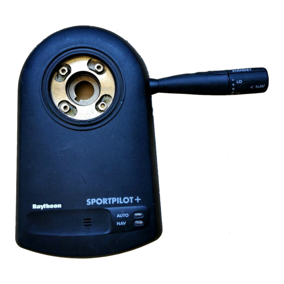
D1356-2 Congratulations on the purchase of your Raymarine SportPilot. The SportPilot fits neatly over the steering column directly behind the steering wheel. All of the autopilot controls are located on a rotary switch at the end of a control stalk. These controls consist of: •... - Page 6 SportPilot and SportPilot Plus specifications There are two versions of the SportPilot: the SportPilot and the SportPilot Plus. It is vital to use the appropriate pilot for your boat. The SportPilot will not perform effectively if you exceed the following boat compatibility specifications.
-
Page 7: About This Handbook
49 Explains how to linearize the SportPilot compass and align its heading. Note: This handbook contains important information about installing, using and main- taining your new Raymarine product. To get the best from the product, please read this handbook thoroughly. -
Page 8: Important Information
Your Raymarine autopilot will add a new dimension to your boating enjoyment. However, it is the skipper’s responsibility to ensure the safety of the boat at all times by following these basic rules: •... -
Page 9: Emc Conformance
The Waste from Electrical and Electronic Equipment (WEEE) Directive requires the recycling of waste electrical and electronic equipment. Whilst the WEEE Directive does not apply to some of Raymarine’s products, we support its policy and ask you to be aware of how to dispose of this product. - Page 10 81057_6.book Page 6 Tuesday, February 21, 2006 2:21 PM ST60 Tridata Instrument Owner’s Manual...
-
Page 11: Chapter 2: Operating The Sportpilot
2.1 Switching on and off Switching on The SportPilot enters Standby mode when the power supply is switched on. This mode is identified by the flashing red AUTO LED. As soon as the pilot is engaged (see below), the red LED glows permanently to confirm this selection. -
Page 12: Making Course Changes
81057_6.book Page 8 Tuesday, February 21, 2006 2:21 PM ST60 Tridata Instrument Owner’s Manual Disengaging the pilot You can disengage the SportPilot at any time by turning the rotary control switch to STANDBY . Making course changes Large course changes When your boat is under autopilot control, you can override the pilot at any time by steering the wheel in the normal way. -
Page 13: Adjusting Autopilot Gain
The autopilot gain setting determines the amount of rudder the pilot applies during course change. Autopilot gain is relative to the speed of your boat.There are five available gain settings on the SportPilot: • LO : lowest gain setting • three mid-range positions •... -
Page 14: Using Navigator (Track) Mode
Initially set the control stalk to the gain position most suited to your boat. The SportPilot will then automatically adjust the gain (up or down) from this setting as your boat speed changes. The SportPilot must receive boat speed information via SeaTalk or NMEA to auto- Note: matically adjust the gain. - Page 15 In Navigator (Track) mode, the SportPilot automatically determines the direction to the target waypoint: • if a turn to port is required, the SportPilot emits 2 short beeps • if a starboard turn is needed, the SportPilot emits 1 short beep To accept the turn, press in the end of the control stalk ( NAV ).
- Page 16 81057_6.book Page 12 Tuesday, February 21, 2006 2:21 PM ST60 Tridata Instrument Owner’s Manual Safety points The SportPilot can only follow a user defined route if the navigation equipment transmits all of the following information: • bearing to waypoint (BTW) •...
-
Page 17: Chapter 3: Maintenance & Fault Finding
• Examine the cables for signs of wear or damage – replace any damaged cables. Cleaning the SportPilot • If the SportPilot is dirty, wipe it with a clean, damp cloth. • Never use chemical or abrasive materials to clean the SportPilot. EMC advice •... -
Page 18: Fault Finding
Raymarine products are supported by a worldwide network of distributors and Authorized Service Representatives. If you encounter any difficulties with this product, please contact either your national distributor, service representative, or the Raymarine Technical Services Call Center. Refer to the back cover or the Worldwide Distributor List for contact details. -
Page 19: Chapter 4: Installing The Sportpilot
Chapter 4: Installing the SportPilot Chapter 4: Installing the SportPilot Introduction The SportPilot fits neatly over your boat’s existing steering shaft with the steering wheel bolted directly onto the pilot. The unit can accommodate either in (19 mm) or 1 in (25 mm) steering shaft tapers using a simple adaptor collar (supplied). -
Page 20: Planning The Installation
81057_6.book Page 16 Tuesday, February 21, 2006 2:21 PM ST60 Tridata Instrument Owner’s Manual 4.1 Planning the installation Steering boss parts Raymarine woodruff key Steering boss Adaptor collar Retaining nuts (3/8in, 1/2in, 5/8in) M4 x 12mm screw and washers (M12 x 1, M16 x 2) -
Page 21: Installation Instructions
81057_6.book Page 17 Tuesday, February 21, 2006 2:21 PM Chapter 4: Installing the SportPilot Installation instructions Before you start installing your SportPilot system, use the illustration to check the parts supplied. Then read through the following information and the relevant installation sections in this chapter. -
Page 22: Emc Installation Guidelines
Connections to other equipment If your Raymarine equipment is to be connected to other equipment using a cable not supplied by Raymarine, a suppression ferrite MUST always be attached to the cable near to the Raymarine unit. -
Page 23: Installing The Compass
Figure 4-1: Fluxgate compass dimensions Compass location To achieve the best performance from the compass, mount it: • With the Raymarine logo facing the bow. Note: If it is not possible to install the fluxgate compass with the logo facing the bow, you must complete the Compass Calibration procedures (see Chapter 5:Compass Calibration). -
Page 24: Compass Mounting
2. Secure the cable at regular intervals with suitable cable clips/ties. You will plug the moulded connector into the COMPASS socket when installing Note: the SportPilot (see page 42). You will also need to attach the supplied suppression ferrite behind the bulkhead as close as possible to the SportPilot. - Page 25 81057_6.book Page 21 Tuesday, February 21, 2006 2:21 PM Chapter 4: Installing the SportPilot D1515-2 Cutting and joining the compass cable You should not cut and rejoin the fluxgate compass cable unless absolutely necessary. If you do have to cut the cable, use Scotchlock connectors to re-join the wires color for color.
-
Page 26: Installing The Rudder Position Sensor - Optional
81057_6.book Page 22 Tuesday, February 21, 2006 2:21 PM ST60 Tridata Instrument Owner’s Manual 4.3 Installing the rudder position sensor – optional A rudder position sensor will improve your SportPilot’s performance by providing precise information about the rudder’s position. CAUTION: If your boat has a hydraulic helm pump, you MUST fit a rudder position sensor for the SportPilot to function accurately. - Page 27 81057_6.book Page 23 Tuesday, February 21, 2006 2:21 PM Chapter 4: Installing the SportPilot Equal travel port and starboard Un-equal travel port and starboard D1676-2 Mounting the linear rudder position sensor 1. Use the steering system to position the bullhorn ram amidships.
- Page 28 1. Connect the linear rudder position sensor cable to the RUDDER REF cable (color for color). Use the Scotchlock connectors and crimp the connectors with a pair of pliers. Connect the cables close to the SportPilot so that the connectors remain dry and Note: free from strain.
-
Page 29: Rotary Rudder Position Sensor - Installation (Hydraulic Inboard Steering Systems)
The rotary rudder position sensor can be used on hydraulic inboard steering systems to transmit the precise position of the boat’s steering to the SportPilot. Depending on your engine installation, you can mount the sensor to the steering arm, or to the tie bar. - Page 30 ST60 Tridata Instrument Owner’s Manual Connecting the sensor to a steering arm Rotary rudder position sensor Steering arm Engine Raymarine steering pin Power steering D1728-2 Figure 4-3: Typical installation – sensor connected to horizontal steering arm Before you attempt to fit the sensor to a steering arm, please consider the following points: •...
- Page 31 81057_6.book Page 27 Tuesday, February 21, 2006 2:21 PM Chapter 4: Installing the SportPilot CAUTION: Before you start installing the rotary rudder position sensor, make sure that you have a spare cotter/split pin available in case the original is lost or cannot be used again.
- Page 32 (or a fabricated mounting base). 3. Remove the pin securing the steering arm to the power steering. 4. Fit the Raymarine steering pin and retain with a split/cotter pin. Note: If your boat has a Volvo steering system, you should fit the plastic spacer to the steering pin (as shown in the following illustration) so the pin does not foul the steering system.
- Page 33 Ideally, dimension A should be 140 mm (5.5 in). However, if necessary it can fall Note: anywhere within the given minimum and maximum limits. This will not affect autopilot performance, but will slightly alter the scaling of the data sent to the SportPilot.
- Page 34 Preventing steering pin movement This section does not apply to Volvo steering systems. Note: If the Raymarine steering pin has excessive vertical free-play after replacing the original steering pin, use the plastic sleeve to reduce or remove any movement (as shown below).
- Page 35 81057_6.book Page 31 Tuesday, February 21, 2006 2:21 PM Chapter 4: Installing the SportPilot • You may need to mount the sensor on a fabricated base (as shown on the illustration) if the distance between the transom and the center of the tie bar is greater than 65 mm (2.5 in).
- Page 36 (color for color). Use the Scotchlock connectors and crimp the connectors with a pair of pliers. Note: Connect the cables close to the SportPilot so that the connectors remain dry and free from strain. 2. Route the cable to the SportPilot, taking into account the EMC installation...
- Page 37 81057_6.book Page 33 Tuesday, February 21, 2006 2:21 PM Chapter 4: Installing the SportPilot You will plug the moulded connector into the RUDDER REF socket when install- Note: ing the SportPilot (see page 42).
-
Page 38: Providing Power For The Sportpilot
(0 V) terminal. 2. Protect the circuit with a 15 A fuse or 10 A thermal over-current circuit breaker (not supplied). 3. Route the cable to the SportPilot. You will plug the moulded end into the POWER/NMEA socket when installing the SportPilot. -
Page 39: Interfacing With Nmea Equipment
81057_6.book Page 35 Tuesday, February 21, 2006 2:21 PM Chapter 4: Installing the SportPilot Interfacing with NMEA equipment Using the NMEA cores in the Power/NMEA cable, the SportPilot can interface directly with equipment capable of transmitting NMEA 0183 data format. Sentences decoded are:... -
Page 40: Connecting Seatalk Equipment
ST60 Tridata Instrument Owner’s Manual 4.5 Connecting SeaTalk equipment You can use the SportPilot’s dedicated SeaTalk port to connect it to SeaTalk instruments or autopilot control units. The SportPilot can then share SeaTalk data with the instruments. It can also provide them with power if required. -
Page 41: Typical Seatalk Connections
Interface cable* *If you only need to connect a remote, plug Extension cable the interface cable into the SportPilot socket Figure 4-9: Connecting SportPilot to ST60 instrument and handheld remote SportPilot (rear) ST600R remote Z101 remote ST50 instrument SeaTalk... -
Page 42: Installing The Sportpilot
81057_6.book Page 38 Tuesday, February 21, 2006 2:21 PM ST60 Tridata Instrument Owner’s Manual 4.6 Installing the SportPilot 137.5 mm (5.4 in) 238.5 mm (9.4 in) 100.5 mm (4.0 in) D1355-2 Step 1 – Remove the steering wheel 1. Turn the wheel all the way over to starboard lock. You MUST do this... -
Page 43: Step 2 - Mount The Torque Bracket
81057_6.book Page 39 Tuesday, February 21, 2006 2:21 PM Chapter 4: Installing the SportPilot Step 2 – Mount the torque bracket inch (19 mm) steering shafts only: assemble the supplied adaptor collar (5) to the shaft. Align the slot in the collar with the slot in the steering shaft. - Page 44 9. Make sure that the lower edge of the torque bracket is level with the bottom of the SportPilot. If your dashboard does not extend below the bottom of the SportPilot, you will Note: need to manufacture an extension (from a suitable material) and permanently attach this...
- Page 45 12. Remove the bolt from the torque restraint. 13. Remove the cable holder from the back of the SportPilot. 14. Apply the self-adhesive template (supplied) to the bulkhead, using the pencil outline as a guide.
-
Page 46: Step 3 - Plug The Cables Into The Sportpilot
D1366-2 16. Remove the template and smooth any rough edges. Step 3 – Plug the cables into the SportPilot 1. Pass the plugged ends of the power, compass, rudder position sensor (if fitted) and SeaTalk cables (if required) through the aperture. -
Page 47: Step 4 - Assemble And Secure The Sportpilot
Step 4 – Assemble and secure the SportPilot 1. Assemble the free end of the torque restraint to the cable holder. 2. Fit the cable holder to the SportPilot using the washers and screws. - Page 48 Torque restraint holder bolt and washer D1370-2 inch (19 mm) taper: Assemble the adaptor collar and the Raymarine woodruff key to the steering shaft. 1 inch (25 mm) taper: Fit the original woodruff key to the steering shaft. 3/4 inch taper...
- Page 49 6. Retain the SportPilot using the split washer and retaining nut. CAUTION: Do NOT attempt to support the SportPilot during tightening. Make sure the torque restraint bolt is removed so the SportPilot is free to rotate as you tighten the retaining nut. This will prevent damage to the SportPilot clutch.
- Page 50 Screws and Steering washers boss Original split washer Wheel Original Nut Washer retaining nut D1373-3 Figure 4-12:Fitting the SportPilot to 1 inch steering shaft 15. Fit the torque restraint bolt and tighten it with the 3 mm allen key (supplied).
- Page 51 81057_6.book Page 47 Tuesday, February 21, 2006 2:21 PM Chapter 4: Installing the SportPilot D1372-2 16. Reposition/reassemble the suppression ferrites close to the bulkhead. Bulkhead Suppression ferrite D3106-2 CAUTION: EMC conformance Always check the installation before going to sea to make sure...
- Page 52 81057_6.book Page 48 Tuesday, February 21, 2006 2:21 PM ST60 Tridata Instrument Owner’s Manual...
-
Page 53: Chapter 5: Compass Calibration
(as described in 4:Installing the SportPilot However, if you are unable to mount the compass in this way or if the SportPilot steers onto the wrong heading, you must carry out compass linearization and heading alignment procedures in this chapter. -
Page 54: Compass Linearization And Heading Alignment
• flashing the red AUTO and yellow NAV lights together, and • emitting a 5 second beep 5. The SportPilot beeps again after the 5 second beep to let you know how much deviation has been detected. Each beep represents 5° of deviation:... -
Page 55: Heading Alignment Without Linearizing
• 4 or more beeps indicate more than 15° of deviation CAUTION: The maximum acceptable deviation is 15°, so the fluxgate compass location is unsuitable if the SportPilot beeps more than 3 times. Re-site the fluxgate compass where there is less magnetic deviation and then repeat the linearization procedure. - Page 56 81057_6.book Page 52 Tuesday, February 21, 2006 2:21 PM ST60 Tridata Instrument Owner’s Manual 1. With the SportPilot in Standby mode, press and hold the end of the control stalk ( NAV ) for 10 seconds – the red AUTO and yellow NAV lights will begin to flash alternately.
- Page 57 For any Raymarine product or system that (i) has been installed on your vessel by a Raymarine-certified service agent or by a Raymarine OEM, and (ii) has a MSRP equal to or greater than USD $2,500, you are eligible to receive warranty service by a Raymarine certified service agent on-board your vessel (‘On Board Warranty Service’) for a period of 12...
- Page 58 Other conditions This Warranty is fully transferable provided that you furnish the original proof of purchase to Raymarine or, in the case of On Board Warranty Service, to a Raymarine-certified service agent. This Warranty is void if the label bearing the serial number has been removed or defaced.
- Page 59 2 years (24 months), subject to the limits contained in this warranty document. In the case of a product installed, by a Raymarine certified OEM installer, on a new boat prior to the sale of the boat to a customer, the 2-year period will begin on the date of the sale of the boat to the customer.
- Page 60 Raymarine Service Agent) at no further cost and promptly returned to the customer. 3.3 In cases where the customer is making a warranty claim and the product has been installed by a Raymarine certified installer, (boat builder, installer, dealer etc.) i.e. Onboard warranty, the nearest Raymarine approved service agent should be contacted and onboard service requested (which will be subject to the limits referred to in paragraph 4.12 below).
- Page 61 81057_6.book Page V Tuesday, February 21, 2006 2:21 PM Raymarine World Wide Warranty 4.10 If repairs are necessary under the warranty, the affected product must be forwarded to a Raymarine facility or a Raymarine approved service agent, at the owner’s expense.
- Page 62 Raymarine Technical Support Raymarine Technical Support +44 (0) 23 9271 4713 1-800-539-5539 or, +1 603-881-5200 Product Repair and Service Product Repair and Service Raymarine Product Repair Center Raymarine plc Anchorage Park 21 Manchester Street, Portsmouth Merrimack, PO3 5TD NH 03054-4801...
Need help?
Do you have a question about the SportPilot and is the answer not in the manual?
Questions and answers