Raymarine ELEMENT E70532 Installation Instructions Manual
Mfd / chartplotter
Hide thumbs
Also See for ELEMENT E70532:
- Operation instructions manual (162 pages) ,
- Installation instructions manual (92 pages)

Related Manuals for Raymarine ELEMENT E70532


Summary of Contents for Raymarine ELEMENT E70532
- Page 1 ELEMENT MFD / CHARTPLOTTER INSTALLATION INSTRUCTIONS English (en-US) Date: 05-2024 Document number: 87380 (Rev 8) © 2024 Raymarine UK Limited...
- Page 3 ) hosting Raymarine product manuals. These websites are not authorized by Raymarine® to do so, and are often hosting illegitimate or older versions of Raymarine product manuals, which may contain inaccurate or misleading information. To obtain the latest official documentation for a Raymarine® product, please visit the official Raymarine® website: https://bit.ly/rym-docs...
-
Page 5: Table Of Contents
CONTENTS CHAPTER 1 IMPORTANT INFORMATION....8 Parts supplied ............. 17 Electronic chart data ............8 CHAPTER 4 COMPATIBLE TRANSDUCERS ..... 18 RF exposure ............... 8 Compatible transducers - Element HV Compliance Statement (Part 15.19) ......8 displays ................19 FCC Interference Statement (Part 15.105 (b)) ... - Page 6 Cleaning the sun cover ........... 57 Compatible autopilot controllers ......37 CHAPTER 13 TECHNICAL SUPPORT......58 CHAPTER 9 POWER CONNECTIONS ....... 39 Raymarine technical support and 13.1 Power connection ............40 servicing ................59 In-line fuse and thermal breaker ratings .....
- Page 7 Learning resources 13.2 ..........61 CHAPTER 14 TECHNICAL SPECIFICATION....62 Element technical specification 14.1 ......63 HyperVision™ technical specification 14.2 ....64 Internal GNSS (GPS / GLONASS) receiver 14.3 specification ..............64 Conformance specification 14.4 ........64 CHAPTER 15 SPARES AND ACCESSORIES .... 66 Spares 15.1 ................
-
Page 8: Chapter 1 Important Information
Electronic chart data Warning: Ensure safe navigation Raymarine does not warrant the accuracy of such information, and is not responsible for damages or injuries caused by errors in chart data This product is intended only as an aid to navigation and or information utilized by the product and supplied by third parties. -
Page 9: Fcc Interference Statement (Part 15.105 (B))
Raymarine UK Ltd compliance with the Radio Equipment Directive 2014/53/EU: Reorient or relocate the receiving antenna. -
Page 10: Warranty Registration
As a result, cannot accept liability for any differences between Raymarine the product and this document. Please check the website Raymarine (https://bit.ly/raymarine-home) to ensure you have the most up-to-date version(s) of the documentation for your product. -
Page 11: Chapter 2 Document And Product Information
CHAPTER 2: DOCUMENT AND PRODUCT INFORMATION CHAPTER CONTENTS • 2.1 Document information — page 12 • 2.2 Applicable products — page 13 • 2.3 Product overview — page 13 • 2.4 Optional additional components — page 14 Document and product information... -
Page 12: Document Information
Please check the website to ensure you have the complete marine electronics. and most recent documentation for your product. • Troubleshoot problems and obtain technical support if required. This and other Raymarine® product documents are available to download Document illustrations in PDF format from www.raymarine.com/manuals... -
Page 13: Applicable Products
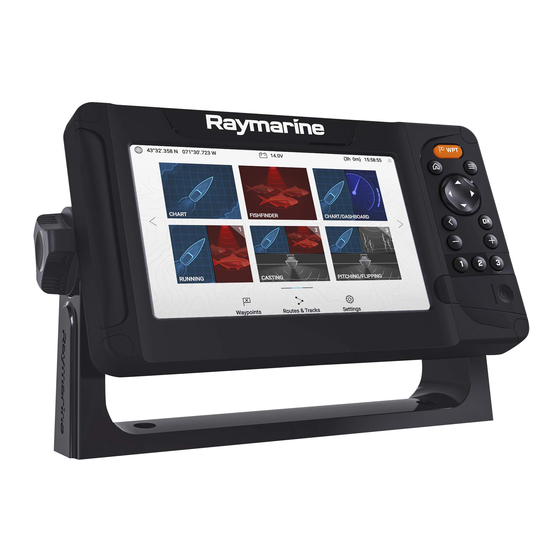
• Supports wireless Quantum™ radar scanner connection. • Send navigation data to connected autopilot. • Supports AIS connection. Part number Description • Personal sonar mapping using Raymarine RealBathy™. E70532 / Element™ 7 HV — HyperVision™ sonar / GPS combo with E70644 Wi-Fi. -
Page 14: Optional Additional Components
Element™ displays are available with and without built-in Wi-Fi. Displays that • Quantum™ radar scanner (E70344, E70210 and E70498) — Connecting include Wi-Fi can connect to the internet and perform over the air software the display to a compatible radar scanner using Wi-Fi enables use of the updates. -
Page 15: Quantum Software Compatibility
The majority of NMEA 2000-compliant tank level sensors are supported. If in doubt as to whether your level sensor is MFDs / chartplotters must be running the software version stated above, compatible, contact Raymarine product support. or later to enable a wireless connection to Radar... -
Page 16: Chapter 3 Parts Supplied
CHAPTER 3: PARTS SUPPLIED CHAPTER CONTENTS • 3.1 Parts supplied — page 17... -
Page 17: Parts Supplied
3.1 Parts supplied The following parts are supplied in the box. Unpack your product carefully to prevent damage or loss of parts. Check the box contents against the list below. Retain the packaging and documentation for future reference. Element™ display. 2. -
Page 18: Chapter 4 Compatible Transducers
CHAPTER 4: COMPATIBLE TRANSDUCERS CHAPTER CONTENTS • 4.1 Compatible transducers - Element HV displays — page 19 • 4.2 Compatible transducers - Element S displays — page 20... -
Page 19: Compatible Transducers - Element Hv Displays
4.1 Compatible transducers - Element HV displays Compatible legacy transducers HyperVision™ transducers DownVision™ transducers The following HyperVision™ transducers can be connected to Element™ HV The following DownVision™ transducers can be connected to Element™ HV displays: displays using the CPT-S / DownVision 9–pin adaptor cable (A80559): Part number Description Part number... -
Page 20: Compatible Transducers - Element S Displays
High CHIRP sonar transducers Legacy transducer Compatible extension cable The following conical beam, high CHIRP sonar transducers can be connected Dragonfly® transducers A80312 — 4 m (13.1 ft) Dragonfly® to Element™ HV displays using the CPT-S/DownVision 9–pin adaptor cable transducer extension cable. (A80559): Note: Part number... -
Page 21: Chapter 5 Product Dimensions
CHAPTER 5: PRODUCT DIMENSIONS CHAPTER CONTENTS • 5.1 Product dimensions — page 22 Product dimensions... -
Page 22: Product Dimensions
5.1 Product dimensions Surface mount dimensions Trunnion mount dimensions Element 7 Element 9 Element 12 239.60 mm (9.43 286.50 mm (11.28 357.20 mm (14.06 Element 7 Element 9 Element 12 135.10 mm (5.32 161.00 mm (6.34 215.20 mm (8.47 263.85 mm 308.40 mm (12.14 373.40 mm (14.70 (10.39 in) -
Page 23: Chapter 6 Location Requirements
CHAPTER 6: LOCATION REQUIREMENTS CHAPTER CONTENTS • 6.1 Selecting a location — page 24 Location requirements... -
Page 24: Selecting A Location
6.1 Selecting a location • Where necessary, cable supports should be used to prevent stress on connectors. Warning: Switch off power supply Electrical interference Ensure the vessel’s power supply is switched OFF before Select a location that is far enough away from equipment that may cause starting to install this product. -
Page 25: Wireless Location Requirements For Optimum Performance
also receive a weaker GPS/GNSS signal. Product mounted below decks Crew members (especially when wet) can also be obstructive to wireless will be more susceptible to performance issues related to the prevailing signals, if their bodies pass through the signal area between wireless sensor conditions. -
Page 26: Emc Installation Guidelines
• Other wireless-enabled products • specified cables are used. Raymarine • Transmitting products that send wireless signals in the same frequency • Cables are not cut or extended, unless doing so is detailed in the range installation manual. • Other electrical, electronic or electromagnetic equipment that may generate interference. -
Page 27: Chapter 7 Installation
CHAPTER 7: INSTALLATION CHAPTER CONTENTS • 7.1 Mounting options — page 28 • 7.2 Trunnion bracket mounting — page 28 • 7.3 Surface mounting — page 29 Installation... -
Page 28: Mounting Options
7.1 Mounting options Important: Trunnion bracket fixings are NOT supplied. Element displays can be either trunnion mounted or surface mounted. Before mounting the display, ensure you have sourced suitable fixings for mounting the display’s trunnion bracket to the desired mounting surface. Fixing type will be determined by the mounting location, and the material type and thickness of the mounting surface. -
Page 29: Surface Mounting
3. Using the bracket knobs, secure the display to the Bracket, ensuring the 1. Remove the 4 screw covers from the corners of the display. ratchet teeth are correctly engaged. The knobs should be tightened by hand, sufficiently to prevent the display from moving whilst your vessel is underway. -
Page 30: Chapter 8 Connections
CHAPTER 8: CONNECTIONS CHAPTER CONTENTS • 8.1 Connections Overview — page 31 • 8.2 General cabling guidance — page 31 • 8.3 Element™ HV transducer connection — page 32 • 8.4 Element™ HV legacy transducer connection — page 33 • 8.5 Element™... -
Page 31: Connections Overview
It is important to use cables of the appropriate type and length. Important: • Unless otherwise stated only use cables supplied by Raymarine An Element display can NOT be connected to the same SeaTalkng ® backbone as a Multifunction • Where it is necessary to use non-... -
Page 32: Element™ Hv Transducer Connection
8.3 Element™ HV transducer connection HV-300THP-P and HV-300THP-S (split pair) connection HV-series transducers can be connected directly to Element™ HV displays. HV-100 connection HV-300THP (all-in-one) connection Extension cable (supplied with split pair sets of transducers). 2. Y-cable (supplied with split pair sets of transducers). You can extend the length of transducer cables using a transducer extension cable. -
Page 33: Transducer Extension Cable
HV–300 transducer extension cable • Secure the cable at regular intervals using the supplied cable clips. For best performance, cable runs should be kept to a minimum. However, for • Any excess cable should be coiled up at a convenient location. some installations it may be necessary to extend the transducer cable. -
Page 34: Legacy Transducer Extension Cables
Legacy transducer extension cables You can extend the length of CPT-S transducer cables using a transducer extension cable A80273 (4 m (13.1 ft) CPT-S transducer extension cable). When connecting a compatible legacy transducer to an Element display, using an adaptor cable: if the cable run requires extending, you must use an extension cable which is compatible with your transducer. -
Page 35: Nmea 2000 Data Compatibility
8.7 SeaTalkng® system example 4. SeaTalkng ® to DeviceNet adaptor cable (A06045 / A06075) connects to SeaTalkng ® backbone. An example SeaTalkng ® system is provided below. Connection to a network provides the display with data from other connected devices. Note: SeaTalkng ®... -
Page 36: Pairing A Quantum-Series Radar Scanner
8.8 Pairing a Quantum-Series Radar scanner 2. RS150 GNSS receiver. 3. Wind vane transducer. You can connect a Radar scanner to your display using the Quantum-Series connection. 4. SeaTalkng ® spur cables. Wi-FI Pre-requisites: 5. iTC-5 convertor. • Ensure you have installed and connected your Radar Quantum-Series 6. -
Page 37: Element Autopilot Connection
2. Enter the SSID and passcode for your Quantum-Series Radar scanner. [Connect] 3. Select 4. Follow any onscreen instructions to continue pairing with your Quantum-Series Radar scanner. The pairing process may take several minutes to complete. For more information on the Radar scanner Quantum-Series pairing process (including troubleshooting information), refer to your... - Page 38 Description ST6002 (E12098–P / E12100–P) ST7002 (E12099–P / E12182) Description ST8002 (E12119–P / E12183) p70s (E70328) S100 (repeat controller only) (E15024) p70Rs (E70329) SmartController (repeat controller only) (E15023) p70 (E22166) p70R (E22167) ST70 (E22105) ST70+ (E22115) SeaTalk ® autopilot controllers...
-
Page 39: Chapter 9 Power Connections
CHAPTER 9: POWER CONNECTIONS CHAPTER CONTENTS • 9.1 Power connection — page 40 Power connections... -
Page 40: Power Connection
If in doubt consult an authorized achieved by connecting directly to a battery, or via the distribution panel. Raymarine® dealer. The product is protected against reverse polarity. • Your product’s power cable may have an in-line fuse fitted, if not then you must add an in-line fuse / breaker to the positive wire of your product’s power connection. -
Page 41: Power Distribution
Power distribution Description Recommendations and best practice for the power connection of products If not supplied already fitted to the power cable, a waterproof fuse supplied with a ground wire as part of the supplied power cable. holder containing a suitably-rated inline fuse must be fitted. For Inline fuse and thermal breaker ratings suitable fuse rating, refer to: •... - Page 42 Description Positive (+) bar Negative (-) bar Circuit breaker If not supplied already fitted to the power cable, a waterproof fuse holder containing a suitably-rated inline fuse must be fitted. For suitable fuse rating, refer to: Inline fuse and thermal breaker ratings Important: Observe the recommended fuse / breaker ratings provided in the product’s documentation, however be aware that the suitable fuse / breaker rating is...
-
Page 43: Power Cable Ground Wire Connection
Ensure that you also observe any additional grounding advice provided in The preferred minimum requirement for the path to ground (bonded or the product’s documentation. non-bonded) is via a flat tinned copper braid, with a 30 A rating or greater. If this is not possible, an equivalent stranded wire conductor may be used, rated as follows: More information... -
Page 44: Chapter 10 Operation
CHAPTER 10: OPERATION CHAPTER CONTENTS • 10.1 Operation instructions — page 45... -
Page 45: Operation Instructions
10.1 Operation instructions For instructions on how to operate your product, refer to the separate Operation Instructions document. Please check the website to ensure you have the latest documentation: Document Number Link Operation 81388 https://bit.ly/element-docs LightHouse Sport Instructions Operation... -
Page 46: Chapter 11 Troubleshooting
CHAPTER 11: TROUBLESHOOTING CHAPTER CONTENTS • 11.1 Troubleshooting — page 47 • 11.2 Software update download troubleshooting — page 47 • 11.3 Downgrading software — page 47 • 11.4 Power up troubleshooting — page 47 • 11.5 GPS / GNSS troubleshooting — page 49 •... -
Page 47: Troubleshooting
1. Insert a Micro SD card containing only the downgraded software version into the display’s card reader slot. Before packing and shipping, all products are subjected to Raymarine comprehensive testing and quality assurance programs. If you do experience 2. Select [Update software]... -
Page 48: Performing A Power On Reset
/ fuses etc, and replace 3. Release the [Power] button. if necessary. [Home] 4. When the Raymarine logo appears, release the button. Incorrect power The power supply may be wired incorrectly, ensure 5. Use the [Down] button to highlight... -
Page 49: Gps / Gnss Troubleshooting
11.5 GPS / GNSS troubleshooting Potential problems with the GPS / GNSS receiver and possible causes and solutions are described here. Problem Possible causes Possible solutions “No Fix” status icon is displayed. or Geographic location or prevailing Check periodically to see if a fix is obtained in better conditions or display keeps losing position fix. -
Page 50: Sonar Troubleshooting
Possible causes Possible solutions Incorrect display software version Display software may be incompatible with your connected transducer. Check the Raymarine website and ensure that the display is running the latest available software. Transducer not connected Connect compatible transducer / Ensure that the transducer cable connector is fully inserted and locked in position and reboot the display. - Page 51 Possible causes Possible solutions Damaged display connector Check that the transducer connector pins on the back of the display are not bent or broken / missing. If damage is detected replace the display or send it to an authorized service agent for repair.
-
Page 52: Radar Troubleshooting
If the breaker Possible Causes Possible Solution keeps tripping or fuses keep blowing, contact a Raymarine authorized dealer for assistance. Radar powered down • Power up the Radar scanner by opening the Radar app and selecting the [Power] icon. -
Page 53: Bearing Alignment
11.8 Bearing alignment 11.9 Wi-Fi troubleshooting The radar’s bearing alignment ensures that radar echoes (objects) appear Before troubleshooting problems with your Wi-Fi connection, ensure that at the correct bearing relative to your vessel’s bow. You should check the you have followed the Wi-Fi location requirements guidance provided in the bearing alignment for any new installation. - Page 54 Cannot connect to network Possible cause Possible solutions Possible cause Possible solutions Interference caused by other Temporarily switch off each device devices that use the 2.4 GHz in turn until you have identified the Trying to connect to the wrong Wi-Fi Ensure you are trying to connect to frequency.
- Page 55 Connection extremely slow and / or keeps dropping out Possible cause Possible solutions Wi-Fi performance degrades over Move display closer to router. distance, so products farther away will receive less network bandwidth. Products installed close to their maximum Wi-Fi range will experience slow connection speeds, signal dropouts or not being able to connect at all.
-
Page 56: Chapter 12 Maintaining Your Display
CHAPTER 12: MAINTAINING YOUR DISPLAY CHAPTER CONTENTS • 12.1 Service and maintenance — page 57 • 12.2 Product care — page 57... -
Page 57: Service And Maintenance
Changes or modifications to this equipment not expressly 2. Wipe the case with a clean, lint-free cloth. approved in writing by Raymarine Incorporated could violate 3. If necessary, use a mild detergent to remove grease marks. compliance with FCC rules and void the user’s authority to operate the equipment. -
Page 58: Chapter 13 Technical Support
CHAPTER 13: TECHNICAL SUPPORT CHAPTER CONTENTS • 13.1 Raymarine technical support and servicing — page 59 • 13.2 Learning resources — page 61... -
Page 59: Raymarine Technical Support And Servicing
Italy (Raymarine subsidiary): Raymarine offers dedicated service departments for warranty, service, and repairs. • E-Mail: support.it@raymarine.com Don’t forget to visit the Raymarine website to register your product • Tel: +39 02 9945 1001 for extended warranty benefits: https://www.raymarine.com/en- Spain (Authorized Raymarine distributor): us/support/product-registration •... -
Page 60: Viewing Hardware And Software Details (Lighthouse™ Sport)
You can view detailed product information about your display. Denmark (Raymarine subsidiary): • E-Mail: support.dk@raymarine.com • Tel: +45 437 164 64 Russia (Authorized Raymarine distributor): • E-Mail: info@mikstmarine.ru • Tel: +7 495 788 0508 Viewing hardware and software details (LightHouse™... -
Page 61: Learning Resources
13.2 Learning resources has produced a range of learning resources to help you get the Raymarine most out of your products. Video tutorials official channel on YouTube Raymarine • http://www.youtube.com/user/RaymarineInc Training courses regularly runs a range of in-depth training courses to help you Raymarine make the most of your products. -
Page 62: Chapter 14 Technical Specification
CHAPTER 14: TECHNICAL SPECIFICATION CHAPTER CONTENTS • 14.1 Element technical specification — page 63 • 14.2 HyperVision™ technical specification — page 64 • 14.3 Internal GNSS (GPS / GLONASS) receiver specification — page 64 • 14.4 Conformance specification — page 64... -
Page 63: Element Technical Specification
14.1 Element technical specification LCD specification Element™ 7 Element™ 9 Element™ 12 Power Size (diagonal): 7.0” 9.0” 12.1” Element™ 7 Element™ 9 Element™ 12 Type TN (Twisted Nematic) IPS (In-Plane Nominal supply 12 V dc Switching) voltage: Color depth: 24 bit Operating 8 V dc to 16 V dc (protected up to 32 V dc) Resolution:... -
Page 64: Hypervision™ Technical Specification
14.2 HyperVision™ technical specification 14.3 Internal GNSS (GPS / GLONASS) receiver specification The following specification only applies to HyperVision™ products. Channels Multiple — ability to simultaneously track up to 28 satellites Sonar channels: • Conical high CHIRP sonar Cold start <2 minutes •... - Page 65 • Australia and New Zealand C-Tick compliance level 2 • Canadian RSS 247 • FCC rules part 15 Technical specification...
-
Page 66: Chapter 15 Spares And Accessories
CHAPTER 15: SPARES AND ACCESSORIES CHAPTER CONTENTS • 15.1 Spares — page 67 • 15.2 Element accessories — page 67 • 15.3 Compatible transducers - Element HV displays — page 67 • 15.4 Compatible transducers - Element S displays — page 69 •... -
Page 67: Spares
15.1 Spares 15.3 Compatible transducers - Element HV displays Part number Description R70523 Power / NMEA 2000 cable (includes 1.5 m (4.92 ft) power HyperVision™ transducers lead and 0.5 m (1.64 ft) NMEA 2000 lead). The following HyperVision™ transducers can be connected to Element™ HV R70647 Element 7”... -
Page 68: Compatible Legacy Transducers
Compatible legacy transducers Part number Description A80448 CPT-S High CHIRP, 12° angled element, Flush mount, DownVision™ transducers Thru-hull, Plastic transducer. The following DownVision™ transducers can be connected to Element™ HV displays using the CPT-S / DownVision 9–pin adaptor cable (A80559): A80447 CPT-S High CHIRP, 20°... -
Page 69: Compatible Transducers - Element S Displays
15.4 Compatible transducers - Element S 15.5 SeaTalk NG cables and accessories displays cables and accessories for use with compatible products. SeaTalk NG SeaTalk NG kits High CHIRP sonar transducers kits enable you to create a simple backbone. SeaTalk NG SeaTalk NG The following conical beam, high CHIRP sonar transducers can be connected Starter kit (part number: T70134) consists of:... - Page 70 2 x Backbone cables 5 m (16.4 ft) (part number: A06036). Used to create converter kit (part number: E22158) consists of: SeaTalk 1 SeaTalk NG and extend the backbone. SeaTalk NG 2. 1 x Backbone cable 20 m (65.6 ft) (part number: A06037). Used to create and extend the backbone.
- Page 71 1 x Power cable 2 m (6.6 ft) (part number: A06049). Used to provide 12 V dc power to the backbone. SeaTalk NG 2. 1 x Spur cable 1 m (3.3 ft) (part number: A06039). Used to connect a spur cables: SeaTalk NG device to the backbone.
- Page 72 Backbone cables: 5-Way connector (part number: A06064). Each connector block allows • Backbone cable 0.4 m (1.3 ft) (part number: A06033). connection of up to 3 devices. Multiple connector blocks SeaTalk NG • Backbone cable 1 m (3.3 ft) (part number: A06034). can be ‘daisy chained’...
- Page 73 • (male) adaptor cable 0.1 m (0.33 ft) (part SeaTalk NG DeviceNet number: A06078). • (male) adaptor cable 0.4 m (1.3 ft) (part SeaTalk NG DeviceNet number: A06074). • (male) adaptor cable 1 m (3.3 ft) (part number: SeaTalk NG DeviceNet A06076).
-
Page 75: Appendix A Nmea 2000 Pgns
Appendix A NMEA 2000 PGNs • 127506 — DC detailed status (Receive) • 127507 — Charger status (Receive) Administration PGNs • 127508 — Battery status (Receive) • 59392 — ISO Acknowledge (Receive / Transmit) • 127509 — Inverter status (Receive) •... -
Page 76: Appendix B Document Change History
Appendix B Document change history • 130070 — Route and WP Service — WP Comment (Receive / Transmit) • 130072 — Route and WP Service — Database Comment (Receive / Document details Changes Transmit) 87360-8 • Added software Quantum • 130074 — Route and WP Service — WP List — WP Name & Position Date: 05–2024 compatibility details to Handbook (Receive / Transmit) - Page 77 Document details Changes 87360-3 • Updated to include details of ‘S’ Date: 04-2019 variant displays and part numbers for non wi-fi enabled variant displays. • Updated to include details for expanded hardware compatibility i.e.: AIS700, iTC-5, Wind vane transducers and RS150 external GPS.
- Page 79 Index Radar ....................36 Contact details..................59 Accessories ..................... 67 SeaTalk NG adaptor cables ..............72 Data item SeaTalk NG backbone cables .............. 71 Compatibility ...................15, 35 SeaTalk NG cables ................69 Declaration of Conformity................9 SeaTalk NG connectors ............... 72 Diagnostics....................60 SeaTalk NG kits ...................
- Page 80 Pairing Installation Quantum radar..................36 Best practice ..................43 PGNs ....................... 75 Surface mounting................. 29 Power surface requirements................24 Battery connection................42 Trunnion mounting ................28 Connection to battery ................42 Ventilation .................... 24 Connection to distribution panel ............41 Interference .....................
- Page 81 System example .................. 35 Service and maintenance ................ 57 Service Center..................59 Servicing....................57 Software ....................47 Software update Storage space..................47 Software updates ..................26 Sonar transducers High CHIRP ..................20, 69 Support forum ..................61 Tank sensors compatibility..................15 Technical specification ................62 HyperVision ..................
- Page 84 Raymarine (UK / EU) Marine House, Cartwright Drive, Fareham, Hampshire. PO15 5RJ. United Kingdom. Tel: (+44) (0)1329 246 700 www.raymarine.co.uk Raymarine (US) 110 Lowell Road, Hudson, NH 03051. United States of America. Tel: (+1) 603-324-7900 www.raymarine.com...
Need help?
Do you have a question about the ELEMENT E70532 and is the answer not in the manual?
Questions and answers