Table of Contents
Advertisement
Quick Links
Advertisement
Table of Contents

Related Manuals for Parker IQAN-LC5-C0 Series


Summary of Contents for Parker IQAN-LC5-C0 Series
- Page 1 IQAN-LC5-C0x Instruction book Publ no: HY33-8404-IB/UK Edition: 2016-05-03...
-
Page 2: Table Of Contents
Contents Contents Introduction ........... . 1 Warnings . - Page 3 Contents MP handle faceplate button numbering for 6 position ... . . 18 MP handle connector, 12 position for C2 connection ....19 Connector, 12 position assignments .
-
Page 4: Introduction
Contact the manufacturer if there is anything you are not sure about or if you have any questions regarding the product and its handling or maintenance. The term "manufacturer" refers to Parker Hannifin Corporation. Instruction book, IQAN- LC5-C0x... -
Page 5: Overview Of Relevant Documentation
Overview of relevant documentation Introduction Overview of relevant documentation The following publications are relevant for users of this product. The main documentation contains information that is not found elsewhere. The additional documentation contains product information in a compact format, for details on the information found in those documents, consult this manual. -
Page 6: Precautions
General safety regulations Precautions Precautions General safety regulations Work on the hydraulics control electronics may only be carried out by trained personnel who are well-acquainted with the control system, the machine and its safety regulations. ARNING Mounting, modification, repair and maintenance must be carried out in accordance with the manufacturer's regulations. -
Page 7: Safety During Start-Up
General safety regulations Precautions Safety during start-up ARNING The machine's engine must not be started before the control system is mounted and its electrical functions have been verified. Ensure that no one is in front, behind or nearby the machine when first starting up the machine. -
Page 8: Product Description
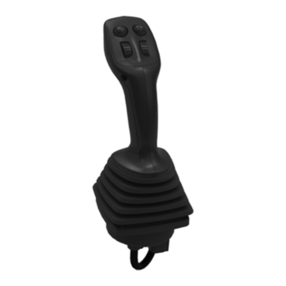
IQAN-LC5-C0x Product description Product description IQAN-LC5-C0x The CAN joystick replaces IQAN-LL (fourth generation) coordinate levers and therefore is called IQAN-LC5 (Lever, Coordinate 5th generation). The designation - C01 (CANbus, type 01) represents the CAN version. The joystick version -C02-U2 is configured to be a drop-in replacement for the IQAN-LL-2U. -
Page 9: The Iqan-Lc5-C0X Control Signals
I/O overview -C01 Product description The IQAN-LC5-C0x control signals The IQAN-LC5-C0x is used to control the object in two directions: • the lever is moved to the right/left, direction X +/-. • the lever is moved forward/back, direction Y +/-. The control signal is proportional to the lever's working range. -
Page 10: Directional Analogue Channels (Dac)
I/O overview -C01 Product description Directional Analogue Channels (DAC) The IQAN-LC5-C01 joystick has five (5) directional analogue channels for use in IQAN applications. These are assigned to X-axis, Y-axis and up to three additional proportional command signals denoted as Z1 thru Z3 (when the -MP handle is used). The DAC channels are sent to the master unit via CAN and defined using IQAN software. -
Page 11: Inputs
I/O overview -C01 Product description Inputs The IQAN-LC5-C01 module has eight (8) voltage inputs in the C2/C3 connectors for internal (-MP handle) or external signals. (8) Voltage inputs VIN-A thru VIN-H There are five (5) digital inputs in the C2 connector for external signals. (5) Digital inputs DIN-A thru DIN-E Outputs For the IQAN-LC5-C01 there is one (1) digital output, DOUT-A. -
Page 12: Mp Handle
MP handle Product description MP handle The IQAN-LC5-C01 is designed to be used with the Multi-Purpose (MP) handle. The MP handle together with a IQAN-LC5-C01 base will have one Deutsch DTM connector for interfacing to connector C2 or C3 in the joystick base. In order to reduce operator fatigue, the MP handle incorporates a hand rest, and is designed for both left and right-handed use. -
Page 13: I/O Overview, Mp Handle
I/O overview, MP handle Product description I/O overview, MP handle POWER +5Vdc OUT-W1A OUT-W1B OUT-W2A GROUND OUT-W2B Buttons and thumbwheels Digital The MP handle has up to nine (9) buttons that are connected as digital inputs on the IQAN-LC5-C01 base. (8) momentary buttons B1 thru B8 (1) momentary trigger button T1 Analogue... -
Page 14: Safety
Redundant signals Safety Safety Redundant signals In order to fulfill high safety demands, the joystick IQAN-LC5-C0x uses dual mirrored sensors per axis. The sensor signals are compared in the controller; both have to show matching activation for that axis to activate, and they have to match over the whole joystick stroke. -
Page 15: Mounting
Mounting the unit Mounting Mounting Mounting the unit OTICE The IQAN-LC5-C0x unit should be mounted according to the following instructions. Mounting considerations • The control lever must be built in so that it is protected against direct pressurized liquid spray (above flange) and excessive mechanical forces. •... -
Page 16: Handle Considerations
When using a handle from a different manufacturer than Parker, be sure to include a suitable bellow made of a material that is able to withstand the stresses of outdoor use in mobile hydraulic machinery. -
Page 17: Handle Configuration To Fit -U2 Bellow
LC5 stem should be metal for strength. OTICE The design shown above is a guideline only! The customer is responsible for developing a suitable handle interface when mounting a non-Parker handle to an IQAN-LC5-C0x-U2 joystick base. Instruction book, IQAN- LC5-C0x... -
Page 18: Installation
IQAN-LC5-C0x connectors Installation Installation IQAN-LC5-C0x connectors Connector kit Parker 5035007 Housing,C1/C3 Deutsch no. DTM06-6S C1/C3 Pin type Deutsch no. 1062-20-0222 Wedge type Deutsch no. WM6S Sealing plug Deutsch no. 0413-204-2005 Housing, C2 Deutsch no. DTM06-12SA Pin type Deutsch no. 1062-20-0222 Lock type Deutsch no. -
Page 19: Connector C2 Pin Assignments (-C01)
Connector C2 pin assignments (-C01) Installation Connector C2 pin assignments (-C01) Symbol Pin No. Function +VREF-A Voltage reference for external sensors. Sourcing +5V. -VREF-A Voltage reference for external sensors. Return (0V). VIN-A Input from -MP handle or external device DIN-F DAC-Z1P VIN-B Input from -MP handle or external device... -
Page 20: Connector C2 Pin Assignments (-C02)
Connector C2 pin assignments (-C02) Installation Connector C2 pin assignments (-C02) Symbol Symbol Function IQANdesign IQANdevelop +VREF-A +VREF-A Voltage reference for external sensors. Sourcing +5V. -VREF-A -VREF-A Voltage reference for external sensors. Return (0V). VIN-A VIN-A Input from external device DIN-G VIN-B VIN-B... -
Page 21: Mp Handle Connector, 6 Position For C3 Connection
MP handle connector, 6 position for C3 connection Installation MP handle connector, 6 position for C3 connection Connector parts Parker 20072408 Housing Deutsch no. DTM06-6S Pin type Deutsch no. 1062-20-0222 Wedge type Deutsch no. WM6S Sealing plug Deutsch no. 0413-204-2005... -
Page 22: Mp Handle Connector, 12 Position For C2 Connection
MP handle connector, 12 position for C2 connection Installation MP handle connector, 12 position for C2 connection Connector parts Parker 20072406 Housing Deutsch no. DTM06-12SA Pin type Deutsch no. 1062-20-0222 Wedge type Deutsch no. WM12S Sealing plug Deutsch no. 0413-204-2005... -
Page 23: Connector, 12 Position Assignments
MP handle connector, 12 position for C2 connection Installation Command +100% +Vref DAC-Z1P DAC-Z1S DAC-Z2P -Vref DAC-Z2S -100% Deflection -100% Neutral +100% position Connector, 12 position assignments MPB2W2T0 MPB2W2T1 MPB4W1T0 MPB4W1T1 Symbol Colour Pin No. Pin No. Pin No. Pin No. +Vref-A -Vref-A Black... -
Page 24: Required Connectors, Based On Model Code
MP handle connector, 12 position for C2 connection Installation Required connectors, based on model code Model code 5035007 kit with 20072408 kit with 20072406 kit with housings for 6 pin housing 12 pin housing C1/C2/C3 for C1 for C2 IQAN-LC5-C01-U1 1 pc IQAN-LC5-C01-U2 1 pc... -
Page 25: Iqan-Lc5-C01 Supply Voltage
IQAN-LC5-C01 supply voltage Installation IQAN-LC5-C01 supply voltage ARNING Before any installation of the IQAN system can take place, make sure the ignition lock is turned off and the battery is disconnected. Emergency stop Make sure an Emergency Stop disconnecting the power supply, is easily accessible at any time. -
Page 26: Iqan-Lc5-C0X Addressing/Terminating
IQAN-LC5-C0x addressing/terminating Installation IQAN-LC5-C0x addressing/terminating Addressing Each IQAN-LC5-C0x module will have a specific address, enabling the master module to communicate with the modules through the CAN-bus. When operating, the system distinguishes between different modules by first verifying the module type and secondly, through the modules having unique addresses. -
Page 27: Reference Voltage, Vref
Reference voltage, VREF Installation Reference voltage, VREF The IQAN-LC5-C0x module is internally equipped with a voltage regulator to generate the reference voltage VREF. The standard reference voltage will feed different kinds of sensors, potentiometers and joysticks. IQAN-LC5-C01 +VREF-A -VREF-A +VREF-B -VREF-B VREF positions in connectors C2 and C3. -
Page 28: Connecting Sensors And Switches To Iqan-Lc5-C01
Connecting sensors and switches to IQAN-LC5-C01 Installation Connecting sensors and switches to IQAN-LC5-C01 Connecting sensors to the voltage inputs The sensor signal range must be 0-5 Vdc. To detect signal errors such as short circuits or interruptions the active signal range is recommended to be within 0.5-4.5 Vdc. Error detection range Active signal range Error detection range... - Page 29 Connecting sensors and switches to IQAN-LC5-C01 Installation Connecting switches to the inputs Switches could be connected to the inputs, to create a digital on/off signal. The switches may be connected to +VREF and DIN respectively for 5Vdc signal. The current consumption for the input is negligible. EXAMPLE Connect the positive and negative terminals of the switch to +VREF, position C2:6, and DIN-A, position C2:4, respectively.
-
Page 30: Start-Up
Start-up procedures Start-up Start-up Start-up procedures This chapter contains instructions for action to be taken in connection with the initial start. ARNING Risk of injury! If the control system is not fitted properly, the machine could move uncontrollably. The machine’s engine shall not be started before the control system is completely fitted and its signals are verified. -
Page 31: System Diagnostics
Start-up procedures System Diagnostics System Diagnostics The yellow blinking LED on the module indicates normal status. If there is an error detected, the master will present a message on the display. The IQAN-LC5-C0x module also indicates error status through the red blinking LED as shown below. This gives an immediate diagnosis as to the nature of the error that has occurred. -
Page 32: Iqan-Lc5-C0X Technical Overview
IQAN-LC5-C0x Technical Overview Appendix A Appendix A IQAN-LC5-C0x Technical Overview IQAN-LC5-C01, base and -MP handle Absolute Maximum Ratings Parameter Remark Ambient temperature, T -40 to 85 °C Storage temperature -40 to 100 °C Maximum voltage supply on +BAT 6 to 36 V, no system reset, power drivers will saturate at low voltage Voltage on any pin with respect to -BAT 36 V External magnetic fields... - Page 33 IQAN-LC5-C0x Technical Overview Appendix A System = +25 °C (unless otherwise specified) Parameter Remark Voltage supply, V 9 to 32 V Current supply =14 V typ. 45 mA typ. 30 mA = 28 V CAN specification CAN 2.0A, CAN 2.0B CAN speed 125 to 500 kbits Protection...
-
Page 34: Iqan-Lc5-C01, -Mp Handle Only
IQAN-LC5-C0x Technical Overview Appendix A = +25 °C (unless otherwise specified) Parameter Remark Accuracy with external sensor supply ±(0.8 % + 5 mV), -40 to 70 °C with VREF sensor supply ±(0.2 % + 5 mV), -40 to 70 °C Maximum continuous voltage 32 V Protection... - Page 35 IQAN-LC5-C0x Technical Overview Appendix A Buttons Parameter Remark Expected life 1.5x10 (tested 1.5x10 cycles) Total travel 1.5 mm Switching point 1.2 mm Operating force 2 to 5 N Max current 400 mA @ 32 VAC, resistive load (from mfg’s documentation) Max current 100 mA @ 50 VDC, resistive load (from mfg’s documentation) Instruction book, IQAN-LC5-C0x...
-
Page 36: Error Codes, Messages And Actions
Error codes, messages and actions Appendix B Appendix B Error codes, messages and actions If one of the following errors are detected, a message will be presented on the master display together with an error code on the module. In some cases, the module will turn off, to increase safety. - Page 37 Error codes, messages and actions Appendix B MODULE IS OFFLINE Situation Error code Action LC5-C01 Comment CAN-bus off Error 3:1 All outputs shuts Check CAN-bus off. ADDR-H < 4,75 V Error 3:2 Check voltage ADDR-H ADDR-H > 5,25 V Error 3:2 Check voltage ADDR-H ADDR-L <...
-
Page 38: Dimensioning Of The Iqan-Lc5-C0X
Dimensioning of the IQAN-LC5-C0x Appendix C Appendix C Dimensioning of the IQAN-LC5-C0x Instruction book, IQAN-LC5-C0x... -
Page 39: Dimensioning Of The Iqan-Lc5 With Mp Handle
Dimensioning of the IQAN-LC5 with MP handle Appendix C Dimensioning of the IQAN-LC5 with MP handle unit = mm Instruction book, IQAN-LC5-C0x... - Page 40 For latest information visit our website www.iqan.com Information in this instructionbook is subject to change without notice Publ no: HY33-8404-IB/UK Edition: 2016-05-03 Parker Hannifin Parker Hannifin Electronic Controls Division Electronic Controls Division SE-435 35 Mölnlycke 1651 North Main Street Sweden...
Need help?
Do you have a question about the IQAN-LC5-C0 Series and is the answer not in the manual?
Questions and answers