
Related Manuals for FlySky FS-G7P


Summary of Contents for FlySky FS-G7P
- Page 1 FS-G7P User Manual Automatic Frequency Hopping Digital System Copyright ©2022 Flysky Technology Co., Ltd. Website...
- Page 2 Th ank yo u fo r pu rchasing our products. Read th e manu al care ful l y to ensure your personal s afety as wel l as the safety o f you r e quip ment . I f yo u enco unte r any prob l ems during us ing, please refer to this m anual fi rst .
-
Page 3: Table Of Contents
Contents Safety ........................1 1.1 Safety Symbols ........................1 1.2 Safety Guide ...........................1 2.Product Introduction ..................2 2.1 Transmitter Overview ........................2 2.2 Receiver Overview ..........................3 2.2.1 Status LED ............................3 2.2.2 Interface ............................3 2.3 Antenna ..............................3 3. Preparation .............................4 3.1 Installing Transmitter Battery ......................4 3.2 Installing Receiver and Servo ......................4 4. - Page 4 7.1 Attentions ............................24 7.2 Binding ............................... 24 7.3 Firmware Update ..........................24 7.4 Failsafe ..............................25 8. Product Specifications ...................26 8.1 Transmitter Specification FS-G7P ....................26 8.2 Receiver Specification FS-R7P ............................27 9. Packing List ......................28 10. Certification ....................29 10.1 DoC Declaration .........................29 10.2 CE Warning .........................29...
-
Page 5: Safety
Safety Safety Symbols Pay close attention to the following symbols and their meanings. Failure to follow these warnings could cause damage, injury or death. Danger • Not following these instructions may lead to serious injuries or death. Warning • Not following these instructions may lead to major injuries. Attention •... -
Page 6: Product Introduction
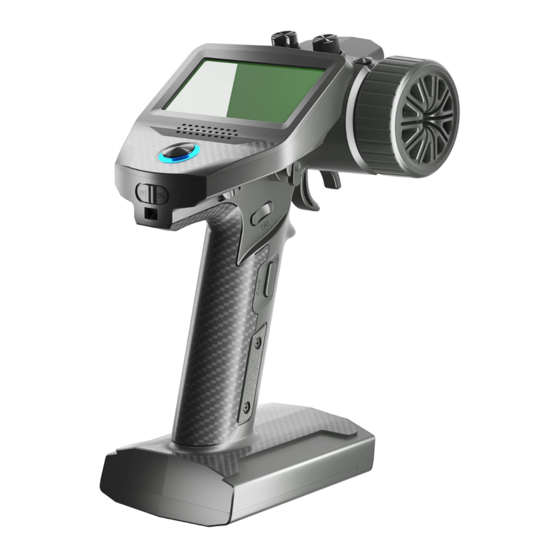
2.Product Introduction This product uses the 2.4 GHz ANT(Ant protocol) enhanced automatic frequency hopping digital system, consisting of FS-G7P transmitter and FS-R7P receiver. It has an output of 7 channels, compatible with model cars, boats, etc. 2.1 Transmitter Overview SW1 Key VR1 Knob... -
Page 7: Receiver Overview
2.2 Receiver Overview [10] [ 1 ] CH 1 /P (P W M /P P M) [ 2 ] -[ 5 ] CH 2 - CH 5 [ 6 ] BI N D in te r fa ce [11] [7] BVD/VCC(Batter y voltage detection/Power supply interface) [ 8 ] CH 7 [ 9 ] S E R VO [12]... -
Page 8: Preparation
FS-G7P Digital Proportional Radio Control System 3. Preparation Prior to operations, please install the battery and connect devices according to the sequence and guide as described in this chapter. 3.1 Installing Transmitter Battery Danger • Only use specified battery (X4 AA batteries). -
Page 9: Operation Guide
• The procedure is applicable to the bind between only FS-G7P transmitter and FS-R7P receiver. The bind methods vary with receivers. For details about the operations, you can visit the FLYSKY official website to obtain the receiver manual or other related information. -
Page 10: Calibration
FS-G7P Digital Proportional Radio Control System system operations and alarms. For system operations and alarms, you can enable/disable the sound separately or collectively. In addition, you can set the sound volume separately. Please follow the steps below to perform the settings: Start the transmitter and enter the SYSTEM menu. -
Page 11: System Interface
5. System Interface Main system interface Enter the main system interface after power-on. Model name and model number Throttle trim display Steering channel(ST) output display Steering trim display Throttle channel(TH) output display Transmitter voltage display Timer Signal and strength DR output display The timer display area of the main interface can be set to display signal strength and BVD voltage information. -
Page 12: Function Menu
FS-G7P Digital Proportional Radio Control System 6. Function Menu Fu nction desc ri pt ion: In th is transmitter, w e h ave classifie d the fun ction s and m ad e a n e w la y ou t . T he re are 8 categories in icons i n tota l. -
Page 13: Settings-Channel Reverse
MODEL SYST EM S ET Fu nction o perati ons: In the main interface , press the O K ke y to en ter the fu n ct io n men u. Se le ct t he f u n cti on categor y by pressing th e UP/ DOWN ke y. -
Page 14: Settings-Neutral Trim
FS-G7P Digital Proportional Radio Control System co rrespond ing st ru ct ure for the b est m atc h, to o btai n th e requi red o perati on ef fect . Fo r exam ple : You want to op erate t hat th e tu rning action is n ot so la rge, y ou can a dju st the va lue of th e directio n channe l at both e nds to be sm aller. -
Page 15: Settings-Curve
6.5 Settings-Curve Cur ve function is used to set the output data cur ve adjustment of the direction channel channel 1, throttl e ch annel c hanne l 2 u ppe r, a nd brake chan n el 2 lo we r ch an n el. Th e ra n ge is -1 00 to + 10 0. It ca n ch ange the ou t pu t se nsi tivity of each chan n el. -
Page 16: Settings-Abs
FS-G7P Digital Proportional Radio Control System 6.8 Settings-ABS This f unction can be u sed to set pulse brakin g, n a mely th e bra kes are relea s e d peri o dica lly w he n braking is trigge red, to pre ve nt skid , dri ft o r un der-tur ni n g du e to lo cke d wh ee ls. -
Page 17: Settings-Idle Up
6.9 Settings-IDLE UP The throttle idle up function i s u se d to set the en gi n e idle s pee d wh en th e f ue l ca r i s i n th e neutral pos ition. Afte r setting the i dle sp eed, y o u ca n preh eat th e en g in e in o rde r to kee p i t f rom sta ll ing . -
Page 18: Settings-Ch Speed
FS-G7P Digital Proportional Radio Control System 6.11 Settings-CH SPEED This f unct ion al lows you to set the stee ri ng speed, fo r wa rd s pe ed a n d bra ke s pe ed. Th e minimum delay is 0 .00S , and maxi mu m d ela y is 10.0 0 S, a n d the de fau lt i s s et to 0 .0 0S. -
Page 19: Mixes
6.13 Mixes Mixes is enabled for some models that require two channels to act in conjunction with each other. The Mix ing ch annel fu ncti on provi de s 1 steer in g m ixes plu s 5 prog ram ma ble mi xes . Function settings: In the main interface, pre ss the OK ke y to en ter the fun ctio n me nu . -
Page 20: Timer
FS-G7P Digital Proportional Radio Control System 6.16 Timer Time r menu provi des two functions: TIMER an d L AP LIST. Functio n s ett ings: In th e main interface, pre ss the O K ke y to enter the fun cti on me n u. T he n s elect th e TI ME R me n u by p re ssing th e UP/ DOWN ke y. -
Page 21: Receiver Settings
th e ed it state. Then adj ust it by pre ssi n g the UP/DOW N. Pre ss retur n a f te r a djust men t . Te st the funct i on to confir m th at all chan n el outputs ope rate n o rma lly a s expe cted. 6.20 Receiver Settings T he RX SET (recei ve r s etti ng ) m enu provi des a n u mber of f un ctio n setti n g me n us to allow y ou to set u p the receive r s yste m in al l aspe cts. -
Page 22: Receiver Settings - Bind Settings
FS-G7P Digital Proportional Radio Control System nor mal ly as expe cted. Note: When th e t ransm itter is tur ned o ff fo r testin g the Fa i l- s afe f un ctio n , pleas e ke ep th e mode l ele vate d and fixed s o as to a void unex pe cted si tuatio n s . -
Page 23: Receiver Settings - Range Test
bind ing operat ion and the Qu ick Sta rt Gui de. Af ter finish ing t he ab ove step, car r y ou t a test to co n f i rm th at all cha n n el ou tputs are f u n ctioning as expecte d. -
Page 24: Receiver Settings -I-Bus Settings Fs-Cev04
FS-G7P Digital Proportional Radio Control System Thre e parameters, nam el y ope rating mod e, batter y ty pe, an d dra g bra ki n g fo rce ca n be setup here.T here are two braki ng m od es as follo ws: th e fi rst mo de i s FOR /BR K/R E U th at m ea n s, the de vice moves for ward whe n pre ssi ng the tri gger fo r a ccelerati on ;... -
Page 25: System Settings
use th is fu nct ion to m ake a copy for qui ck s ettin g. RESET: It literally m eans th at this function will reset a ll th e s et va lues of th e mo del pa ram ete rs and restore the factor y setti ngs. -
Page 26: System Settings - Stick Calibration
Functio n s ettings: Note: T his fu nction i s only avai lab le in the FlySky A ss i sta nt s of tware prov ide d by F LYSKY. In th e F W UP DATE me nu, a dial og box will pop up. At th i s ti me , y ou ca n sele ct YE S by p re s s ing th e UP/DOWN ke y and press the O K ke y to star t the update s es s i on . -
Page 27: System Settings - Factory Reset
FLYSKY a nd customer s i n future. -
Page 28: Fs-R7P Function Instructions
T he f ir mware of t hi s rece ive r can b e u pdated thro ugh th e F ly s k y A s s i sta n t (On ly v ers i o n 3 .0 or a bov e is s upported. The fir mwa re of Flysky A ss istan t is a vai lable o n the Fly s k y o f f ic ia l we bs ite ). -
Page 29: Failsafe
• Pow er on t he re ce ive r fir st , th en p res s an d ho ld th e BI ND butto n fo r more th a n ten s econd s, whe n the LED of th e receiv eroperates in th re ef la s h- o n e -of f ma n n er repeated ly, t hen release t he BIND bu tton . -
Page 30: Product Specifications
Digital Proportional Radio Control System 8. Product Specifications Th is ch apte r contains the sp ec ifications of FS -G7 P tra n sm itter a n d FS - R 7P recei ve r. 8.1 Transmitter Specification FS-G7P Prod uct Name FS-G7P... -
Page 31: Receiver Specification
8.2 Receiver Specification FS-R7P Product N ame FS -R7P Compati ble Trans mi tte rs FS-G7P (Transmitter with ANT protocol) Compati ble Model s Car s or boats PW M Chan nel s 2.4G Hz ISM Maximum Power <20dBm (e .i.r.p.) (EU)... -
Page 32: Packing List
FS-G7P Digital Proportional Radio Control System 9. Packing List Transmi tter *1( FS -G 7P) Receiver*1(FS -R7 P) Website... -
Page 33: Certification
10. Certification 10.1 DoC Declaration Hereby, [F lys ky Te ch nolo g y co., l td] d eclare s that the Rad io Eq uip me nt [FS - G7 P] an d [ FS -R 7P ] are in co mpliance wi t h R ED 2 01 4 /5 3 /EU. The f ull text of t h e EU Do C i s avai la ble at the foll owing inte rnet add re s s: w ww.fl y s ky te ch .co m / info_detail /10.h tml 10.2 CE Warning... -
Page 34: Environmentally Friendly Disposal
FS-G7P Digital Proportional Radio Control System 11. Environmentally Friendly Disposal O ld electri cal appl i ance s mu st not be di spose d of toget he r with the resi dual wa ste, bu t h ave to be disp ose d of separately. - Page 35 Copyright ©2022 Flysky Technology Co., Ltd. Date:2022-12-22 Website FCC ID: N4ZG7P 00 FCC ID:2 A2 UNR7P 00 Manufacturer:ShenZhen FLYSKY Technology Co., Ltd. Address: 16F, Huafeng Building, 6006 Shennan Road, Futian District, Shenzhen, Guangdong province, China...
Need help?
Do you have a question about the FS-G7P and is the answer not in the manual?
Questions and answers