
Related Manuals for FlySky Absima FS-G11P


Summary of Contents for FlySky Absima FS-G11P
- Page 1 Schnellstart-Anleitung FS-G11P Quick Start Guide Guide de démarrage rapide www.absima.com info@absima.com Copyright © ���� Flysky Technology Co., Ltd.
- Page 2 Vielen Dank, dass Sie die Produkte von Flysky gekauft haben! Wenn Sie mehr über unsere Produkte zu erfahren möchten, besuchen Sie unsere Website unter www.flysky-cn.com. Sollten Probleme auftauchen, lesen Sie bitte zuerst in der Bedienungsanleitung nach. Wenn das Problem nicht gelöst werden kann, wenden Sie sich bitte direkt an Ihren Händler vor Ort.
- Page 3 oder unmittelbar nach der Benutzung Hitze entwickeln kann. Das Triebwerk oder der Motor können sehr heiß sein und schwere Verbrennungen verursachen. - Die falsche Verwendung dieses Produkts kann zu schweren Verletzungen oder zum Tod führen. Um Ihre Sicherheit und die Ihrer Ausrüstung zu gewährleisten, lesen Sie dieses Handbuch und befolgen Sie die Anweisungen sorgfältig.
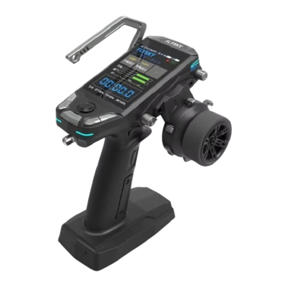
- Page 4 Transmitter Overview K5 Knopf / VR1 Knopf TR3 Trimmen Lenkrad (CH1) Display TR1 Trimmen TR2 Trimmen SW1 Knopf Fünf-Wege-Schalter, (Menü Navigationstaste K1 Knopf K4 Knopf K2 Knopf K3 Knopf POWER-Taste (Einschalttaste, lang drücken/ Return-Taste, kurz drücken)
- Page 5 Umgebungsbeleuchtung Umgebungsbeleuchtung Befestigungsloch für Handy-Halterung SW4 3-Stellungsschalter SW3 3-Positionsschalte VR2 3-Gang-Wahlrad TR4- K6 Kippschalter Feineinstellungsknopf SW2 Drei- K7 Knopf Positionen-Schalter Videospiel-Controller Batteriefach JST-Schnittstelle Symmetrischer Ladeanschluss (2.54mm*3P)...
- Page 6 ein Griff SD-Kartensteckplatz Gaspedalabzug (CH2) Einstellen der Loch für Abzugsgröße Schlüsselband Einstellen der Abzugsspannung Hand Gel Einstellen der Einstellen des Handrad-Dichtigkeit Weges der gesamten USB-Typ-C Auslösestruktur -Anschluss Einstellbarer Drehhub des Handrads 3,5-mm-Audioanschluss (DSC)
-
Page 7: Basic Operations
Basic Operations Einsetzen der Batterie 18650 Gehen Sie wie folgt vor, um die 18650er-Batterie zu installieren: �. Öffnen Sie das BatteriefachAbdeckung wie abgebildet. 2. Legen Sie 2 Batterien in das Fach ein. Vergewissern Sie sich dass die Batterien richtig eingelegt sind entsprechend der Polarität auf der Batterie markiert sind 3. - Page 8 Schließen Sie ein Ende des USB-Typ-C-Kabels an die Stromquelle und das andere Ende an den USB-Typ-C-Anschluss des Senders. Bitte verwenden Sie das Standard-Ladekabel des Senders zum aufzuladen. Eine unsachgemäße Verwendung kann den Akku beschädigen und und seine Lebensdauer beeinträchtigen. Fünf-Wege-Schalter (Menü-Navigationstaste) und POWER- Taste(Power/Return-Taste) Die Funktionen des Fünf-Wege-Schalters (Menünavigationstaste) und der POWER-Taste (Power/Return-Taste) werden im Folgenden beschrieben.
- Page 9 um Funktionspunkte auszuwählen; drücken Sie kurz die mittlere Taste, um die ausgewählte Funktion zu aktivieren. Im Funktionsmenü: Drücken Sie kurz die Tasten Auf, Ab, Links und Rechts um Funktionen auszuwählen; drücken Sie kurz die mittlere Taste zum Bestätigen; drücken Sie lange auf die mittlere Taste, um alle Funktionsdaten auf der aktuellen Seite auf die Standardwerte zurückzusetzen.
- Page 10 Stromversorgung trennen, bevor Sie den Sender ausschalten. Andernfalls kann es zu einem Verlust der Kontrolle kommen. Eine unangemessene Einstellung der Failsafe-Funktion kann zu Unfällen führen. Die LED dieses Senders umfasst die oberen und die unteren Umgebungslichter. Obere Umgebungslichter: Stellen Sie die Farben und Helligkeitsstufen der oberen Umgebung- slichter ein.
- Page 11 Untere Umgebungslichter Stellen Sie die Farben und Helligkeitsstufen der unteren Umgebungsbe- leuchtung ein. Die Funktionen und Einstellungen sind dieselben wie bei den oberen Umgebungslichtern, siehe Beschreibung der oberen Umgebungslichter. Stick Kalibration Verwenden Sie diese Funktion, um die mechanische Abweichung des Gashebels, des Lenkrads und des VR2 3-Positionen-Einstellrads zu korrigieren, z.B.
- Page 12 Nicht eingestellt: Der Failsafe-Wert wurde nicht eingestellt, und es erfolgt keine Ausgabe im Falle einer Außer-Kontrolle. Kein Ausgang: Es gibt keinen Ausgang für den i-BUS/PPM/PWM-Kanal. Mit Ausgang: Der i-BUS/PPM/PWM-Kanal gibt jeweils den eingestellten Wert aus. Sie können für jeden Kanal einen Wert von 1 bis 11 einstellen. Standardmäßig ist dieser Wert der Messwert des aktuellen Kanalaus- gangswertes.
- Page 13 Binding Der Sender und der Empfänger wurden vor der Auslieferung gebunden. Wenn Sie andere Empfänger verwenden möchten, führen Sie die folgenden Schritte aus, um den Sender und den Empfänger zu binden. Der Sender unterstützt sowohl ANT 2 Way und ANT 1 Way Bindung, und ANT 2 Way Bindung ist die Standardeinstellung.
-
Page 14: Firmware Update
Firmware aktualisiert wird. Diese Firmware kann auf die folgenden zwei Arten aktualisiert werden. - Die Firmware dieses Senders kann über den Flysky Assistant aktualisiert werden (Die Firmware des Flysky Assistant ist verfügbar auf der offiziellen Website von Flysky www.flysky-cn.com). - Page 15 Empfängern Firmware Update Das Firmware-Update des FS-R11P-Empfängers sollte über FlySkyAssis- tant durchgeführt werden (wird nur von Version 3.0 und höher unterstützt, FlySkyAssistant Firmware kann von der offiziellen Website www.flysky-cn.com bezogen werden). Die Firmware des Empfängers kann auf die folgenden zwei Arten aktualisiert werden: Modus I: Nach dem Binden zwischen dem Sender und dem Empfänger (die LED des Empfängers leuchtet), verbinden Sie den Sender mit dem...
-
Page 16: Spezifikationen
Spezifikationen • Produktmodel: FS-G11P • Passende Empfänger: FS-R11P(mit ANT Protokoll) • Kompatibele RC Modelle: Cars und Boote • Kanäle: 11 • RF: 2.4GHz ISM • Maximum Power: < 20dBm (e.i.r.p.) (EU: • RF Protokol: ANT • Auflösung: 4096 • Datenübertragung: USB Type-C, 3.5mm Audio Jack(DSC), SD Slot •... - Page 17 Empfänger angeschlossen ist. dem der Empfänger angeschlossen ist. Wenden Sie sich an ihren Händler, um Hilfe zu erhalten. EU DoC Declaration Hereby, [ShenZhen FLYSKY Technology Co., Ltd.] declares that the radio equipment type [FS-G11P]is in compliance with Directive 2014/53/EU.
- Page 18 Der vollständige Text der EU-Verordnung ist unter folgender Internetadresse abrufbar: www.flyskytech.com/info_detail/10.html Umweltverträgliche Entsorgung Elektroaltgeräte dürfen nicht mit dem Restmüll entsorgt werden Restmüll entsorgt werden, sondern sind getrennt zu entsorgen. Die Entsorgung über die kommunalen Sammelstelle durch Privatpersonen ist kostenlos. Der Besitzer von Altgeräten ist dafür verantwortlich, die Geräte zu diesen oder ähnlichen Sammelstellen...
- Page 19 Dieser Sender darf nicht in Verbindung mit einer anderen Antenne oder einer anderen Antenne oder einem anderen Sender betrieben werden. Das tragbare Gerät ist so konstruiert, dass es die Anforderungen für die Belastung durch für Funkwellen zu erfüllen, die vom Markt der Europäischen Union (Frankreich) festgelegt wurden.
- Page 20 2. Der maximale SAR-Wert beträgt 1,509 W/kg, wenn das Telefon 0 mm in der Nähe des Benutzers verwendet wird. VORSICHT -Ersatz eines Akkus mit einem falschen Typ, der eine Schutzvorrichtung außer Kraft setzen kann (z. B. bei einigen Lithium-Akkutypen); -Einwerfen eines Akkus ins Feuer oder in einen heißen Ofen oder mechanisches Zerquetschen oder Zerschneiden einer Batterie, was zu einer Explosion führen kann;...
- Page 21 Zertifikation Garantiebestimmungen Mit dem Erwerb und Gebrauch Ihres Absima Produkts erklären Sie sich mit den Garantiebestimmungen der Absima GmbH einverstanden. Die Garantie bezieht sich nur auf bereits beim Kauf des Produktes vorhandene Material- und/oder Funktionsmängel. Von der Garantie ausgeschlossen sind: •...
- Page 22 Konformitätserklärung Hiermit erklärt der Hersteller, dass sich das Produkt in Übereinstimmung mit den grundlegenden Anforderungen und den übrigen einschlägigen Bestimmungen der EU Richtlinie befindet. Die Konformitätserklärung kann unter http://absima.com/index.php/downloads/erklaerungen/ eingesehen werden oder unter Absima GmbH ‒ Gibitzenhofstraße 127a/RG ‒ 90443 Nürnberg angefordert werden.
- Page 23 Thank you for purchasing the products of Flysky! To find out more about our products, visit our website at www.flysky-cn.com. If you encounter any problems during using, please refer to the manual first. If the problem is still not resolved, contact your local dealer directly or contact the customer service staff via Flysky official website.
-
Page 24: Transmitter Overview
• Misuse of this product may lead to serious injury or death. To ensure the safety of you and your equipment, read this manual and follow the instructions carefully. • Make sure the product is properly installed in your model. Failure to do so may result in serious injury. - Page 25 Lower Ambient Upper Ambient Light Light Cell Phone Holder Mounting Hole SW4 3-Position Switch SW3 3-Position VR2 3-Position Dial Switch TR4 Trim K6 Toggle Switch K7 Button SW2 3-Position Switch Handle Battery Compartment JST Port Balanced Charging Port (2.54mm*3P)...
- Page 26 Carring Handle Neck Strap Hook SD Card Slot Throttle Trigger (CH2) Throttle Trigger Size Neck Strap Adjustment Hook Throttle Trigger Tension Adjustment Grip Throttle Trigger Steering Wheel Structure Tension Travel Adjustment USB Type-C Adjustment Port Steering Wheel Rotate Travel Adjustment 3.5mm Audio Jack (DSC)...
- Page 27 Basic Operations Installing the 18650 Battery Follow the steps below to install the 18650 battery: 1. Open the battery compartment cover as shown. 2. Insert 2 batteries into the compartment. Make sure that the batteries are well set according to the polarities marked on the battery compartment. Press and slide forward to remove the 3. Close the battery compartment battery compartment cover. cover. Installing the LiPo Battery The transmitter supports LiPo batteries which are equipped one JST connector or one balanced charging connector of the battery wiring.
- Page 28 Connect one end of the USB Type-C cable to the power source and the other end to the transmitter USB Type-C port. Please use the standard charging cable of this transmitter to charge it. Improper use may cause damage to the battery and affect its service life. Five-way Switch(Menu Navigation Button) and POWER button (Power/Return Button) The functions of five-way switch (Menu Navigation Button) and the POWER button (Power/Return Button) are described as follows.
-
Page 29: Powering Off
to select functions; short press the Middle button to confirm; long press the Middle button to reset all the functional data on the current page to default values. In the Function Menu Settings state (the function item is flashing), • Short press the Down or Up button to adjust the value or function item;... - Page 30 off the transmitter. Failure to do so can result out of control. Unreasonable setting of the Failsafe may cause accidents. This transmitter's LED includes the upper ambient lights (located on both sides of the cell phone holder mounting hole) and lower ambient lights (located on both sides of the POWER button).
-
Page 31: Stick Calibration
Lower Ambient Lights Set the colors and brightness levels of the lower ambient lights. The functions and settings are the same as the upper ambient lights, refer to the description of Upper Ambient Lights. Stick Calibration Use this function to correct for the mechanical deviation of the throttle trigger, steering wheel and VR2 3-Position Dial, for example, deviation occurred in the self-centering or maximum/minimum travel. - Page 32 No Output: It is no output for i-BUS/PPM/PWM channel. With Output: i-BUS/PPM/PWM channel output respectively the set value. Namely, you can set a value respectively for each channel from 1 to 11. By default, this value is the reading of current channel output value. Setup: 1. Enter the function interface through the Home > Main Menu > RX Set > Failsafe. Short press the...
- Page 33 Binding The transmitter and the receiver have been pre-bound before delivery. If you need to use other receivers, follow the steps below to bind the transmitter and the receiver. The transmitter supports both ANT 2 Way and ANT 1 Way binding, and ANT 2 Way binding is the default setting. The transmitter will display the information returned by the receiver after the ANT 2 Way binding is completed.
- Page 34 LED changes to slow flash, and at the same time, the receiver LED is solid on, indicating that the binding is completed. 2. The binding mode may vary according to the receiver model. Visit the Flysky official website to check the receiver manual or other relevant information. Firmware Update To put the transmitter into updating state.
- Page 35 The FS-R11P receiver firmware update should be done through FlySkyAssistant (only supported by version 3.0 and later, FlySkyAssistant firmware can be got from the official website www.flysky-cn.com). This receiver fimware can be updated via the following two ways: Mode Ⅰ : After the binding between the transmitter and the receiver (the LED of the receiver is solid on), connect the transmitter to the computer, then open the FlyskyAssistant on the computer to update the firmware.
-
Page 36: Specifications
Specifications • Product Model: FS-G11P • Compatible Receiver: FS-R11P(Receivers with ANT protocol) • Compatible RC Model: Cars or boats • Number of Channels: 11 • RF: 2.4GHz ISM • Maximum Power: < 20dBm (e.i.r.p.) (EU) • RF Protocol: ANT • Resolution: 4096 •... - Page 37 -- Connect the equipment into an outlet on a circuit different from that to which the receiver is connected. -- Consult the dealer or an experienced radio/TV technician for help.. EU DoC Declaration Hereby, [ShenZhen FLYSKY Technology Co., Ltd.] declares that the radio equipment type [FS-G11P]is in compliance with Directive 2014/53/EU.
- Page 38 The full text of the EU DoC is available at the following internet address: www.flyskytech.com/info_detail/10.html Environmentally friendly disposal Old electrical appliances must not be disposed of together with the residual waste, but have to be disposed of separately. The disposal at the communal collecting point via private persons is for free.
- Page 39 the specific operating instructions for satisfying RF exposure compliance. This transmitter must not be co-located or operating in conjunction with any other antenna or transmitter. The portable device is designed to meet the requirements for exposure to radio waves established by European Union market(France). These requirements set a SAR limit of 4W/kg averaged over ten gram of tissue.
- Page 40 2. The maximum SAR value is 1.509W/kg when the phone used 0mm close to user. CAUTION - replacement of a battery with an incorrect type that can defeat a safeguard (for example, in the case of some lithium battery types); - disposal of a battery into fire or a hot oven, or mechanically crushing or cutting of a battery, that can result in an explosion;...
-
Page 41: Warranty Terms
Certification Warranty Terms By purchasing and using your Absima product, you agree to the warranty terms of Absima GmbH. The warranty applies only to material and/or functional defects already present at the time of purchase of the product. Excluded from the guarantee: ·... -
Page 42: Declaration Of Conformity
Declaration of conformity The manufacturer hereby declares that the product complies with the essential requirements and other relevant provisions of the EU Directive. The declaration of conformity can be found at http://absima.com/index.php/downloads/erklaerungen/ or can be consulted under Absima GmbH - Gibitzenhofstrasse ���a/RG D - �����... - Page 43 Merci d'avoir acheté les produits de Flysky ! Pour en savoir plus sur nos produits, visitez notre site web à l'adresse www.flysky-cn.com. Si vous rencontrez des problèmes lors de l'utilisation, veuillez d'abord vous référer au manuel. Si le problème n'est toujours pas résolu, contactez directement votre revendeur local ou contactez le service clientèle via le...
- Page 44 • Ne touchez aucune partie du modèle susceptible de produire de la chaleur pendant son fonctionnement ou immédiatement après son utilisation. Le moteur peut être très chaud et provoquer de graves brûlures. • Ne touchez aucune partie du modèle susceptible de produire de la chaleur pendant son fonctionnement ou immédiatement après son utilisation.
- Page 45 Aperçu de l'émetteurer Bouton K5 / bouton VR1 Microcontrôleur TR3 Volant de direction (CH1) Affichage Commande de micro- réglage TR1 Microcontrôleur Touche SW1 Commutateur à cinq voies (touche de navigation dans le menu) Bouton K1 Touche K4 Bouton K2 Touche K3 Bouton POWER (bouton d'alimentation, pression longue) / bouton arrière, pression courte)
- Page 46 Lumière ambiante Lumière ambiante Trou de montage du support de téléphone portable SW4 Interrupteur à 3 positions SW3 Interrupteur à 3 VR2 Cadran à 3 positions positions TR4 Garniture K6 Interrupteur à bascule K7 Bouton SW2 Interrupteur à 3 positions Poignée Compartiment des piles JST Port...
- Page 47 Fente pour carte SD Poignée de transport Gâchette d'accélérateur (CH2) Réglage de la taille de la gâchette d'accélérateur Crochet pour corroie de cou Réglage de la tension de la gâchette d'accélérateur Poignée Réglage de la Réglage de la course de la tension du volant structure de la...
-
Page 48: Opérations De Base
Opérations de base Installation de la batterie 18650 Suivez les étapes ci-dessous pour installer la batterie 18650 : 1. Ouvrez le couvercle du compartiment de la batterie comme indiqué. 2. Insérez 2 piles dans le compartiment. Veillez à ce que les piles soient bien placées conformément aux polarités indiquées sur la pile. - Page 49 Connectez une extrémité du câble USB Type-C à la source d'alimentation et l'autre extrémité au port USB Type-C de l'émetteur. Veuillez utiliser le câble de charge standard de cet émetteur pour le charger. Une utilisation incorrecte peut endommager la batterie et affecter sa durée de vie.
- Page 50 Dans le menu principal, Appuyez brièvement sur les boutons Haut, Bas, Gauche et Droit pour sélectionner les éléments de fonction ; Appuyez brièvement sur le bouton du milieu pour accéder à l'élément de fonction sélectionné. Dans le menu des fonctions, Appuyez brièvement sur les boutons Haut, Bas, Gauche et Droit pour sélectionner les fonctions ;...
- Page 51 2. Appuyer longuement sur la touche POWER jusqu'à ce que l'écran s'éteigne, indiquant que l'émetteur est hors tension. Veillez à déconnecter l'alimentation du récepteur avant d'éteindre l'appareil. éteindre l'émetteur. Le non-respect de cette consigne peut entraîner une perte de contrôle. Un réglage déraisonnable du Failsafe peut provoquer des accidents.
-
Page 52: Dispositif De Sécurité
Lumières d'ambiance inférieures Définissez les couleurs et les niveaux de luminosité des lumières ambiantes inférieures. Les fonctions et les réglages sont les mêmes que pour les lumières ambiantes supérieures, voir la description des lumières ambiantes supérieures. Calibrage du bâton Cette fonction permet de corriger la déviation mécanique de la gâchette d'accélérateur, du volant et du cadran VR2 à... - Page 53 Pas de sortie : Il n'y a pas de sortie pour le canal i-BUS/PPM/PWM. Avec sortie : le canal i-BUS/PPM/PWM émet respectivement la valeur définie. Vous pouvez définir une valeur pour chaque canal de 1 à 11. Par défaut, cette valeur correspond à la lecture de la valeur de sortie du canal actuel.
- Page 54 Liaison L'émetteur et le récepteur ont été reliés avant la livraison. Si vous devez utiliser d'autres récepteurs, suivez les étapes ci-dessous pour relier l'émetteur et le récepteur. L'émetteur prend en charge la liaison ANT 2 voies et ANT 1 voie, et la liaison ANT 2 voies est le réglage par défaut.
-
Page 55: Mise À Jour Du Logiciel
Le mode de liaison peut varier en fonction du modèle de récepteur. Visitez le site officiel de Flysky pour consulter le manuel du récepteur ou d'autres informations pertinentes. Mise à jour du logiciel Pour mettre l'émetteur en mode de mise à... - Page 56 Mise à jour du logiciel du récepteur La mise à jour du logiciel du récepteur FS-R11P doit être effectuée par l’intermédiaire de FlySkyAssistant (uniquement pris en charge par la version 3.0 et ultérieure, le micrologiciel FlySkyAssistant peut être obtenu sur le site officiel www.flysky-cn.com). Ce logiciel de réception peut être mis à...
-
Page 57: Spécifications
Spécifications • Modèle du produit : FS-G11P • Récepteur compatible : FS-R11P (Récepteurs avec protocole ANT) • Modèle RC compatible : Voitures ou bateaux • Nombre de canaux : 11 • RF : 2.4GHz ISM • Puissance maximale : < 20dBm (e.i.r.p.) (UE): •... -
Page 58: Déclaration De Conformité Fcc
--Consulter le revendeur ou un technicien radio/TV expérimenté pour obtenir de l'aide. Déclaration de DoC de l'UE Par la présente, [ShenZhen FLYSKY Technology Co., Ltd] déclare que l'équipement radio de type [FS-G11P]est conforme à la directive 2014/53/UE. - Page 59 Le texte intégral de la DoC de l'UE est disponible à l'adresse Internet suivante: www.flyskytech.com/info_detail/10.html Élimination écologique Les anciens appareils électriques ne doivent pas être jetés avec les ordures ménagères résiduelles, mais doivent être éliminés séparément. Le dépôt à la déchetterie communale par des particuliers est gratuit. Le propriétaire des anciens appareils est responsable de les apporter à...
- Page 60 Cet émetteur ne doit pas être placé à proximité ou fonctionner en conjonction avec une autre antenne ou un autre émetteur. L'appareil portable est conçu pour répondre aux exigences d'exposition aux ondes radio établies par le marché de l'Union européenne (France). Ces exigences fixent une limite DAS de 4 W/kg en moyenne sur dix grammes de tissu.
- Page 61 Prudence - le remplacement d'une batterie par un type incorrect qui peut endommager un dispositif de sécurité (par exemple, dans le cas de certains types de batteries au lithium) ; - l'élimination d'une batterie dans un feu ou un four chaud, ou l'écrasement ou le découpage mécanique d'une batterie, qui peuvent entraîner une explosion ;...
-
Page 62: Conditions De Garantie
Certification Conditions de garantie En achetant et en utilisant votre produit Absima, vous acceptez les conditions de garantie de Absima GmbH. La garantie ne s'applique qu'aux défauts matériels et/ou fonctionnels déjà présents au moment de l'achat du produit. Exclus de la garantie : ·... -
Page 63: Déclaration De Conformité
Déclaration de conformité Le fabricant déclare par la présente que le produit est conforme aux exigences essentielles et aux autres dispositions pertinentes de la directive européenne. La déclaration de conformité peut être consultée à l'adresse suivante http://wp.absima.com/index.php/downloads/erklaerungen/ ou peut être consulté sous Absima GmbH - Gibitzenhofstrasse ���a/RG - �����...
Need help?
Do you have a question about the Absima FS-G11P and is the answer not in the manual?
Questions and answers