Table of Contents
Advertisement
Quick Links
Advertisement
Table of Contents

Related Manuals for DTS ARTEMIO PROFILE


Summary of Contents for DTS ARTEMIO PROFILE
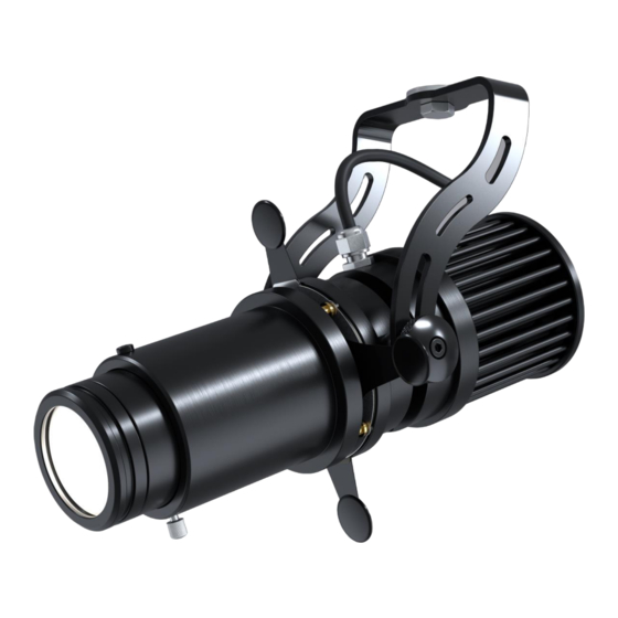
- Page 1 ARTEMIO PROFILE USER’S MANUAL rel. 1.1 GB...
- Page 2 Le informazioni contenute in questo documento sono state attentamente redatte e controllate. Tuttavia non è assunta alcuna responsabilità per eventuali inesattezze. Tutti i diritti sono riservati e questo documento non può essere copiato, fotocopiato, riprodotto per intero o in parte senza previo consenso scritto della D.T.S . D.T.S.
- Page 3 1- SYMBOLS Graphic symbols used on this manual: THIS SYMBOL MEANS “SUITABLE FOR INDOOR USE ONLY” THIS SYMBOL INDICATES THE MAXIMUM OPERATING AMBIENT TEMPERATURE THIS SYMBOL MEANS “DO NOT STARE AT THE OPERATING LIGHT SOURCE” THIS SYMBOL INDICATES PHOTOBIOLOGICAL SAFETY THIS SYMBOL INDICATES THE EUROPEAN COMMUNITY DIRECTIVE 2012/19/EC ON WASTE ELECTRICAL AND ELECTRONIC...
-
Page 4: Technical Features
4- TECHNICAL FEATURES DTS Product codes: 03.ART002 ARTEMIO PROFILE 3000K 03.ART009 ARTEMIO PROFILE 4000K 03.ART011 ARTEMIO PROFILE 5000K Optical group codes: 03.ART003 ULTRA-NARROW LENS (8°) 03.ART013 NARROW LENS (13°) 03.ART004 NARROW LENS (18°) 03.ART005 MEDIUM LENS (24°) 03.ART006 WIDE LENS (33°) - Page 5 Physical IP20 Internal system with four removable shutters Adjusting yoke Weight: 1.1 Kg Finishing: Black Certifications DIMENSIONS...
-
Page 6: Important Safety Information
5- ACCESSORIES Optional (on request) ● Filter holder - black finishing (code 03.ART015) ● Holographic filter soft-edge (code 0506A132.D19) ● Holographic filter 60°x10° (code 0506A092.D19) ● Gobo holder (code 03.ART007) ● Shutter blade (code 03.ART016) ● 2 x 0,5 mm² cable (code 0509C120) ●... -
Page 7: Installation
7- INSTALLATION The unit is suitable for dry locations only. ARTEMIO PROFILE can be installed on a truss or on the ceiling. It is recommended the use of appropriate clamps to fix the unit to the mounting surface. ATTENTION: A safety cable (code 0521A010) must be securely fixed to the unit’s mounting bracket and to the support structure of the projector as shown in the picture below. - Page 8 8- OPTICAL GROUP INSTALLATION 5 different interchangeable optics are available for ARTEMIO PROFILE. 1) Loose the indicated knob and the mechanical end position screw to remove any optical group already installed. 2) Put in place a different optical group by keeping the marked side outward.
-
Page 9: Filter Holder Installation
9- FILTER HOLDER INSTALLATION The Filter Holder for ARTEMIO PROFILE (code 03.ART015) and holographic filters are available on demand. 1) To install the holographic filter remove the metal spring from the holder. 2) Put in place the holographic filter by keeping the microstructure faces inward. - Page 10 10- GOBO HOLDER INSTALLATION The Gobo Holder for ARTEMIO PROFILE (code 03.ART007) is available on demand. 1) Put in place the Gobo Holder on ARTEMIO as shown in the picture. 2) Fix it by tightening the knob. Knob to fix Gobo Holder...
-
Page 11: Gobo Dimensions
11- GOBO DIMENSIONS Gobos should be made in either dichroic glass or metal. Gobo dimensions are as follows: ø external (ED) = 24.5 mm + 0 / - 0,1 mm ø of image (ID) = 15.0 mm max thickness = 1.1 mm Max thickness 1.1 mm Coated side... - Page 12 12- ROTATING SYSTEM Grub screw to loose to rotate the system PROJECTION WITH GOBOS: PROJECTION WITH SHUTTER BLADES:...
- Page 13 13- CONNECTIONS ARTEMIO PROFILE is provided with 2 x 0,5 mm² cable (2 m length). RED wire = LED BLACK wire = LED 700mA Max 700mA Max 36Vdc Min 36Vdc Min...
-
Page 14: Wiring Diagrams
14- WIRING DIAGRAMS The maximum number of ARTEMIO PROFILE connectable to each output channel of the DRIVENET 28 EZ is 1 piece. The maximum distance between DRIVENET 28 EZ and ARTEMIO PROFILE unit should not exceed 100 meters. - Page 15 14- WIRING DIAGRAMS The maximum number of ARTEMIO PROFILE connectable to each output channel of the DRIVENET 832 is 1 piece. The maximum distance between DRIVENET 832 and ARTEMIO PROFILE unit should not exceed 100 meters.
- Page 16 14- WIRING DIAGRAMS The maximum number of ARTEMIO FRESNEL connectable to each output channel of the DRIVENET 28C DIN @ 48Vdc is 1 piece. The maximum distance between DRIVENET 28C DIN @ 48Vdc and ARTEMIO FRESNEL unit should not exceed 100 meters.
- Page 17 NOTES...
- Page 18 NOTES...
- Page 19 NOTES...
- Page 20 ISO 9001:2015 DTS quality system is certified 9001:2015 standard 0517I344 D.T.S. Illuminazione s.r.l. ● Via Fagnano Selve 12- 47843 Misano Adriatico (RN) Italy ● Tel.: +39 0541 611131 Fax +39 0541 611111 info@dts-lighting.it www.dts-lighting.it...
Need help?
Do you have a question about the ARTEMIO PROFILE and is the answer not in the manual?
Questions and answers