Table of Contents
Advertisement
Quick Links
Advertisement
Table of Contents

Related Manuals for DTS BRICK


Summary of Contents for DTS BRICK
- Page 2 Le informazioni contenute in questo documento sono state attentamente redatte e controllate. Tuttavia non è assunta alcuna responsabilità per eventuali inesattezze. Tutti i diritti sono riservati e questo documento non può essere copiato, fotocopiato, riprodotto per intero o in parte senza previo consenso scritto della D.T.S . D.T.S.
-
Page 3: Table Of Contents
INDEX: 1- SYMBOLS ......................... 4 2- GENERAL WARNING ....................5 3- GENERAL WARRANTY CONDITIONS ..............5 4- TECHNICAL FEATURES ..................5 5- ACCESSORIES ......................7 6- IMPORTANT SAFETY INFORMATION ..............8 6.1 Fire prevention...................... 8 6.2 Prevention of electric shock .................. 8 6.3 Safety ........................ -
Page 4: 1- Symbols
1- SYMBOLS Graphic symbols used on this manual: THIS SYMBOL INDICATES A HOT SURFACE THIS SYMBOL INDICATES ELECTRIC SHOCK RISK THIS SYMBOL INDICATES GENERAL RISK THIS SYMBOL INDICATES THE MAXIMUM OPERATING AMBIENT TEMPERATURE THIS SYMBOL MEANS “SUITABLE FOR MOUNTING ON NORMALLY FLAMMABLE SURFACES”... -
Page 5: 2- General Warning
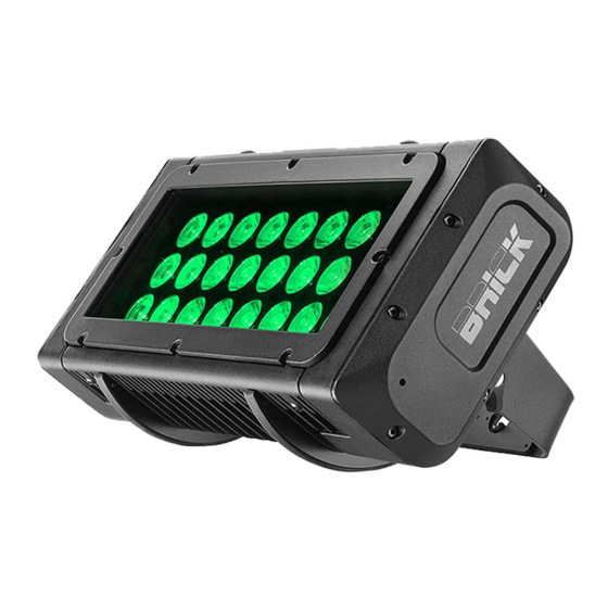
BRICK is suitable for various purposes, offering a range of projection angles quickly interchangeable (no tools required). BRICK comes with an IP65 power cable plus 2 DMX cables with M / F XLR connectors (all IP65), that make it perfect for temporary lighting applications, but also for safe long-lasting installations. - Page 6 4- TECHNICAL FEATURES Control DMX 512 / RDM 10 DMX channels (Default) 4-digit 7-segment LED display + 4 soft keys Protection IP 65 Power supply Built-in full-range PSU 100-240Vac 50-60 Hz Consumption: 400VA Max Connections Power supply: 3 x 1 sq mm cable (1,5 m length) DMX In/Out: 0,7 m cable with XLR 5 pins IP65 connector Operating ambient temperature -10°...
-
Page 7: 5- Accessories
DIMENSIONS 5- ACCESSORIES As standard 1 x Holographic filter 20° (code 0506A043.D11) 1 x Holographic filter 40° (code 0506A045.D11) 1 x Holographic filter 60°x10° (code 0506A092.D11) 1 x PowerCON TRUE1 female cable connector (code 0520P066) 1 x PowerCON TRUE1 male cable connector (code 0520P067) 1 x User’s Manual Optional (on request) - Bracket for ground installation (code 03.LA.213) -
Page 8: 6- Important Safety Information
-High voltage is present inside the unit. Unplug the unit prior to performing any function which involves touching the inside of the projector. -The level of technology inherent in the BRICK requires the assistance of specialised personnel for all servicing. -
Page 9: Waste Electrical And Electronic Equipment (Weee) Directive
7- INSTALLATION The unit is suitable for wet locations. For outdoor installation, BRICK is provided with a Display UV Protection. BRICK may be either floor or ceiling mounted. For floor mounting installation, a bracket with 4 rubber mounting feet (code 03.LA.213) - Page 10 The supporting structure from which the unit is hung should be capable of bearing the weight of the unit, as should any clamps used to hung it. For outdoor application where BRICK needs to be installed vertically keep the unit display towards the floor.
-
Page 11: Protection Against Liquids
7.1 Protection against liquids If IP65 protection is impaired for any reason, do not expose this product to external atmospheric agents, because it could be damaged. 7.2 Movement The projector has a maximum movement of 110° for Tilt. 7.3- Risk of fire Each fixture produces heat and must be installed in a well-ventilated place. -
Page 12: Forced Ventilation
7.4- Forced ventilation You will note, on inspection, that the unit features various air inlets and cooling fans. These should, under no circumstances, be blocked or obstructed whilst the projector is in operation. Doing so could cause the fixture to seriously overheat thereby compromising its proper operation. -
Page 13: Internal Fuse
8.1- Internal Fuse Attention: the fuse replacement must be made by DTS personnel or experienced person. Wrong operations can damage the IP65 protection. To access the internal fuse loose the 6 marked screws which fix the lateral cover on display panel opposite side and remove the cover. -
Page 14: 9- Dmx Signal Connection
9- DMX SIGNAL CONNECTION: The unit operates using a digital DMX 512 signal. Connection between the controller and the unit or between units must be carried out using a two pair screened ø 0.5 mm. Ensure that the conductors do not touch each other. Do not connect the cable ground to the DMX connector chassis. -
Page 15: Dmx Addresses
9.1 DMX addresses BRICK can be controlled with 10 DMX channels (Default). In order to use the unit in 10 DMX channels mode (Default), set the following addresses on the mixer: Projector 1 A001 If you want to select the next projector, just add “10”... -
Page 16: 11- Firmware Updating
Updating the software version. Please follow the procedure below to perform the update: 1. Install the DTS RED BOX USB-DMX driver on the PC you will use to update the unit software. 2. Connect the DTS RED BOX interface to a spare USB port on the PC (be sure that internal switch on DTS RED BOX is set to COM). -
Page 17: 12- Display Functions
Using these options, it is possible to change the fixture’s setting. Changing the DTS settings can vary the functions of the unit so that it does not respond to the DMX 512 used to control it. Carefully follow the instructions below before carrying out any variations or selections. - Page 18 MAIN MENU LEVEL 1 LEVEL 2 LEVEL 3 FUNCTION Display normal orientation for floor mounting position (Default) Display inverted orientation for suspended mounting position Display always ON (Default) Display goes OFF after 10 seconds ...
- Page 19 MAIN MENU LEVEL 1 LEVEL 2 LEVEL 3 FUNCTION In DMX Recorder mode it is possible to create and store the scenes of the CHPR menu by using an external DMX controller. The unit must be set to 10 DMX ...
-
Page 20: 13- Rec Mode
13- REC MODE DMX Recorder mode For the programming of ChPr by using a DMX controller, besides the 10 channels necessary to control the unit a further 3 DMX channels are needed. So that in RECORDER mode (via DMX) the unit will need 13 channels to be correctly programmed. -
Page 21: 15- Periodic Cleaning
Periodically check all mechanical parts and the gaskets. Please refer to an authorised DTS service centre for any operation involving of the unit if needed. Electrical components: Check for unit proper earthing. Please refer to an authorised DTS service centre for any operation involving of the unit if needed. Fuse replacement: Locate the internal fuse, which protects the electronics, in the BRICK. -
Page 22: 17- Holographic Filter Installation
17- HOLOGRAPHIC FILTER INSTALLATION BRICK offers a range of holographic filters quickly interchangeable (no tools required). To properly install the holographic filter: 1 - Put in place the bottom edge of the filter. 2 - Bend the filter. 3 - Insert the top edge of the filter. -
Page 23: 18- Lenses Set Replacement
18- LENSES SET REPLACEMENT Attention: the lenses set replacement must be made by DTS personnel or experienced person. Wrong operations can damage the IP65 protection. 1 – Remove the front screen with the protection glass by loosing the 8 marked screws. -
Page 24: 19- Barndoor Installation
The Barndoor for BRICK (code 03.LA.210) is available on demand. Fix the barndoor on the BRICK by using the 4 marked knobs provided in the box. Once installed, fix the safety cable on the lateral cover by using the screw provided in... -
Page 25: 20- Dmx Protocol
20- DMX PROTOCOL 10 CHANNELS MODE (Default) GREEN BLUE WHITE SHUTTER DIMMER DIMMER FINE MACRO COLOR FUNCTIONS Name DMX levels 0..255 Proportional color from min to max GREEN 0..255 Proportional color from min to max BLUE 0..255 Proportional color from min to max WHITE 0..255 Proportional color from min to max... - Page 26 Name DMX levels MACRO COLOR 0..14 No function 15..24 COL 1: LEE FILTER NO. 19 "FIRE" (R255 G16 B0 W0) 25..34 COL 2: LEE FILTER NO. 20 "MEDIUM AMBER" (R255 G84 B0 W0) 35..44 COL 3: LEE FILTER NO. 25 "SUNSET RED" (R255 G48 B2 W0) 45..54 COL 4: LEE FILTER NO.
- Page 27 Name DMX levels FUNCTIONS (staying 0..14 No function on desired option for 15..24 SMOOTH OFF 5 seconds) FUNCTIONS (staying 25..26 SMOOTH 1 (25 ms) on desired option for 5 seconds) 27..28 SMOOTH 2 (50 ms) 29..30 SMOOTH 3 (75 ms) 31..32 SMOOTH 4 (100 ms) (DEFAULT) 33..34...
- Page 28 “RGBW” MODE (4 CHANNELS) GREEN BLUE WHITE Name DMX levels 0..255 Proportional color from min to max GREEN 0..255 Proportional color from min to max BLUE 0..255 Proportional color from min to max WHITE 0..255 Proportional color from min to max...
- Page 29 NOTES...
- Page 30 NOTES...
- Page 31 NOTES...
- Page 32 DTS. DTS reserves the right to make any aesthetic, functional or design modifications to any of its products without prior notice. DTS assumes no responsibility for the use or application of the products or circuits described herein.
Need help?
Do you have a question about the BRICK and is the answer not in the manual?
Questions and answers