Table of Contents
Advertisement
Quick Links
Advertisement
Table of Contents

Subscribe to Our Youtube Channel
Related Manuals for TECPEL DCM-043


Summary of Contents for TECPEL DCM-043
-
Page 2: Table Of Contents
CONTENTS TITLE PAGE Safety Information …………………………………..1 Environmental Conditions…………………………….….. 1 Explanation of Symbols……………….…………………. 1 Specification ……………………………………….…… 2 General Specification……………………………………. 2 Electrical Specification…………………………………..3 III. Instrument Familiarization ………………………… 4 Symbol Definition………………………………………….. 4 Instrument Familiarization………………………………... 4 Button Instruction…………………………………………..5 IV. Measuring Instruction …………………...………….. 6 4.1 ACA measurement…………………………………. -
Page 3: Safety Information
Instruction Manual Safety Information Do not operate the unit if the casing or the test Leads are or look damaged. Check the main function dial to ensure it is set at the correct position before each measurement. Do not perform resistance and continuity test on a live “powered “system. -
Page 4: Specification
Instruction Manual II. Specification General Specification: Digital Display: 4 digits LCD display with maximum reading 9999 Over Load: When the signal input exceeds the maximum limit “ ” will be display. Sample Rate: 2 times/sec Peak Hold Sample Rate: 10ms at DCV, DCA Low Power Indication: When the battery is below the proper operation range, symbol will appear on the LCD display. -
Page 5: Electrical Specification
Instruction Manual Electrical Specification: ( Ⅰ ) The accuracy specification is defined as ± ( …%reading + …count ) At 23 ± 5 ℃ , ≦ 80 %RH ACA (Autorange) Range Resolution Accuracy ( 50Hz~500Hz) Overload Protection 2%+10 150Arms 10mA 80~100A 10mA 3.5%+10... -
Page 6: Instrument Familiarization
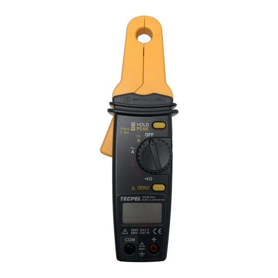
Instruction Manual III. Instrument Familiarization: Symbol Definition: Relative Indicator Peak Hold Alternate/Direct Signal Data Hold Low Battery Continuity Ampere Indicator Auto Power Off Indicator Voltage Indicator Digital Reading Instrument Familiarization: 600V CAT II 100A HOLD ZERO 600V CAT II 300V CAT III 600V... -
Page 7: Button Instruction
Instruction Manual Current Sensing Clamp Positive input terminal ○ ○ Safety protection ring Function select dial ○ ○ Clamp opening handle Peak / Data hold button ○ ○ LCD display Zero button ○ ○ COM input terminal ○ Button Instruction: Zero Button △... -
Page 8: Measuring Instruction
Instruction Manual IV. Measuring Instruction: 4.1 ACA measurement: Switch the function selector to A~ range. Open the clamp by pressing the jaw-opening handle and insert the cable to be measured into the jaw. Close the clamp and get the reading from the LCD panel. Note: Before this measurement, disconnect any test lead with the meter for safety. -
Page 9: Dca Measurement
Instruction Manual 4.2 DCA measurement: Switch the function selector to A range. Press ZERO button to enter the zero reading. Open the clamp by pressing the jaw-opening handle and insert the cable to be measured into the jaw. Close the clamp and get the reading from the LCD panel. Note: Before this measurement, disconnect any test lead from the meter for safety. -
Page 10: Acv Measurement
Instruction Manual 4.3 ACV Measurement: WARNING! Maximum Input Voltage is 600V AC/DC. Do not attempt to Take any voltage measurement that may exceed this maximum to avoid Electrical shock hazard and/or damage to this instrument. Switch the function selector to V range. -
Page 11: Dcv Measurement
Instruction Manual 4.4 DCV measurement: Switch the function selector to V range. Connect red test lead to “+” terminal and black one to the “ COM “ terminal. Measure the voltage by touching the test lead tips to the test circuit where the value of voltage is needed. Read the result from the LCD panel. -
Page 12: Resistance Measurement
Instruction Manual 4.5 Resistance measurement: Switch the function selector to range. Connect red test lead to “+” terminal and black one to the “ COM ” terminal. Connect tip of the test leads to the points where the value of the resistance is needed. Read the Ohm value from the LCD panel. -
Page 13: Continuity Test
Instruction Manual 4.6 Continuity Test: Switch the function selector to range. Connect red test lead to “+” terminal and black one to the “ COM ” terminal. Connect tip of the test leads to the points where continuity is to be tested. If the resistance is under 100Ω, the beeper will sound continuously. -
Page 14: Analog Signal Output
Instruction Manual 4.7 Analog Signal Output: Switch the function selector to A or A~ range. Connect red test lead to “+” terminal and black one to the “ COM ” terminal. Connect tip of the test leads to the meter or oscilloscope input terminal. -
Page 15: Battery Changing
Instruction Manual V. Battery Changing: 1.When the battery voltage drops below proper operation range the symbol will appear on the LCD display and the battery will need to be changed. 2.Before changing the battery, switch the function selector to “OFF ” and disconnect test leads. Open the back cover using a screw driver.
Need help?
Do you have a question about the DCM-043 and is the answer not in the manual?
Questions and answers