Table of Contents
Advertisement
Quick Links
Advertisement
Table of Contents

Related Manuals for TECPEL PHS-864


Summary of Contents for TECPEL PHS-864
- Page 1 CONTENTS Precautions For Use Introduction...
-
Page 2: Table Of Contents
Electrical Symbols Model Technical Specification Instrument Structure Operation Method Battery Replacement Assembly Details Accessories... - Page 3 Precautions For Use Thank you for purchasing the PHS-864 Phase Detecor, manufactured by Tecpel Co., Ltd. In order to better understand the use of this product, please familiarise yourself with its functions before use and keep this user manual for future reference.
-
Page 4: Electrical Symbols
PHS-864 Phase Detecor break circuit searching, break point location, lines maintenance and so on. -
Page 5: Model
Model Model Diameter of wires can be clamped PHS-864 ø1.6mm-ø16mm Technical Specification Phase detection(positive phase, anti-phase, default phase), live line Function detect, simple power electricity detect, break point location, lines maintenance Power Supply DC 3V AA alkaline batteries (LR6)×2PCS,continuous working for 70hours Electricity Testing AC 70~1000V,45~65Hz (sine wave continuous input) - Page 6 Auto Shutdown 5 minutes after booting up, the meter will automatically shutdown Meter Dimension 70mm×75mm×30mm Clamp Lead Length 0.6m Meter Weight 200g Working ;below 80%rh ~55 ℃ ℃ Temperature Store Temperature ;below 90%rh ~60 ℃ ℃ Max Measure AC 1000V Voltage Insulation Strength 5.4kVrms...
-
Page 7: Instrument Structure
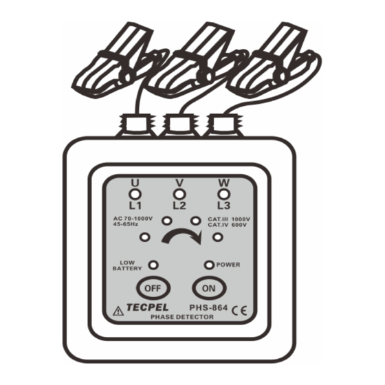
Instrument Structure 1. Operate indication panel 6. L1 phase indicator lamp 11. “ON” Start Up Key 2. Test Clamps 7. L3 phase indicator lamp 12. “OFF” Shut down key 3. Clamp Lead Wire 8. Phase sequence indicator lamp (4 lamps) 13. - Page 8 Danger! High voltage! Please pay attention to safety! 6.1.1 Connection: Clamping on three phase wires respectively with the three clamps (Shown in Fig-1). 6.1.2 The detected wire at the clamp with mark “ ” (Shown in Fig-2). Fig-1 Fig-2 6.1.3 Press the red color “ON” startup key, the power indicator lamp will light up. If the power lamp does not light up, this will indicate either a low battery or a damaged instrument, in which case you will need to replace the battery or send it for repair.
- Page 9 6.1.6 Press white color “OFF” key to shut down, the instrument will automatically shut down after about 5 minutes without any operation to reduce battery consumption. Live wire inspection, simple electricity detection. Danger! High voltage! Please pay attention to safety! 6.2.1 Use any clamps to clamp on the tested wire.
-
Page 10: Battery Replacement
Battery Replacement Pay attention to the battery polarity! 7.1. Before replacing the battery, the clamp must be removed from the tested wire. Do not replace the battery during the test. 7.2. Press “OFF” key to shut down. (Figure A) 7.3. Loosen the screw on the back of instrument and remove the battery cover (Figure B). -
Page 11: Faq
step 3. Fault Phenomenon Possible Causes Solution Without batteries Install batteries Wrong battery type Replace with right type Low battery power Replace the new batteries Cannot power unit Faulty battery polarity Install batteries in correct polarity (LED power indicator Poor contact of battery Replace the battery contacts does not light up, contacts... -
Page 12: Assembly Details
Defect of circuit Repair or replace the PCB component Assembly Details... -
Page 13: 10. Accessories
10. Accessories Instrument 1 PCS Carry Box 1 PCS Instrument Bag 1 PCS Manual 1 PCS... - Page 14 Tecpel Co., Ltd. 3F., No.12, Lane. 130, MinQuan Road., XinDian Dist., New Taipei City 23141, TAIWANP TEL: 02 -2218 3111 company responsible loss damage caused use. The contents of this user manual cannot be used as a reason to use the product for special purposes.
Need help?
Do you have a question about the PHS-864 and is the answer not in the manual?
Questions and answers