Bentone STG 146/2 Biogas Installation And Maintenance Instruction
Hide thumbs
Also See for STG 146/2 Biogas:
- Installation and maintenance instruction (48 pages) ,
- Installation and maintenance instruction (40 pages)

Related Manuals for Bentone STG 146/2 Biogas


Summary of Contents for Bentone STG 146/2 Biogas
- Page 1 178 089 26-1 P93783 2022-11-16 Providing sustainable energy solutions worldwide Installation- and maintenance instruction STG 146/2 Biogas LME23.331C2 DMV-DLE 512 FRS 510 VPS 504 Translation of the original instructions.
- Page 2 1~230V 1,0A 50Hz IP 20 Motor supply MADE IN SWEDEN BY 1. Manualer på övriga språk 1. Manuals in other languages 1. Manualer på andre sprog 2. www.bentone.com\ 2. www.bentone.com\ 2. www.bentone.com\ nedladdning eller scanna download or scan QR-code. download eller scan QR-koden.
-
Page 3: Table Of Contents
Handing over of the installation ........38 Function LME................14 Control program at faults; fault mode indicator LME ..15 Troubleshooting ..............39 Mounting ................17 Service- and inspection protocol ........41 Gas nozzle ..................18 De-aerating ...................18 Tightness control .................18 5.4 Calculation of gas flow ...............19 Bentone... -
Page 4: General Information
Make sure that the burner is suitable for the application (see Technical • Data). All components must be installed without being bent, twisted or • subjected to mechanical or thermal forces that affect components. 172 515 01-2 2021-10-05 Bentone... -
Page 5: What To Do If You Smell Gas
Prevent open fl ames or sparking, e.g. do not turn lights on or off, do • not use any electrical appliances or mobile phones. • Evacuate the building. Notify the installer or gas supplier of the problem so that it can be • rectifi ed. Bentone... -
Page 6: Technical Data
• Dimensions STG 146/2 øB Flame tube Flame tube Length of flame tube measure A measure B ø104 ø104 * Min. recommended distance to floor. 2.1.1 Measurements for connection to boiler Ø 110 Ø 140-170 12.5 172 535 29 Bentone... -
Page 7: Capacity Range
Alt.2 The burner’s noise level can be reduced by connecting the burner’s air intake to the air duct that opens into an appropriate location. Installation must be done so it does not prevent air supply to the burner. Bentone... -
Page 8: Working Field
Basic settings should only be seen as setting values to get burner to start. Once the burner has started and established flame, it is necessary to adjust the settings so that they are adapted to the installation and the fuel used. Air settings Nozzle assembly Scale Burner output Bentone... -
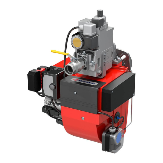
Page 9: Components
Components Fixing fl ange Nozzle assembly adjustment Filter Transformer Flame tube Air setting Brake plate Gas pressure switch min. Connection, Gas valve Gas valve Ignition electrode Pressure regulator Motor Bentone... - Page 10 Flame detector Valve proving system VPS Fan wheel Air pressure switch Bentone...
-
Page 11: Skeleton Diagrams
Skeleton diagrams Gas valve (MultiBloc) Ball valve Filter Governor Gas pressure switch, min Main valve Safety valve Valve proving system 172 535 36 2022-11-16 Bentone... -
Page 12: Installation
Connection must be done in accordance with the applicable • regulations. • Connection must conform to the wiring diagram. If any electrical connection other than that recommended by Enertech is used, there is a risk of property damage and personal injury. 172 535 09-2 Bentone... -
Page 13: Electric Equipment
Electric equipment Safety system The safety system (safety switch for hatches, doors, water level, pressure, temperature and other safety devices) must be installed in the safety circuit in accordance with current regulations for the system. If these safety requirements are met by other means, safety circuits must be bypassed/jumpered. -
Page 14: Function Lme
4.2.1 List of components Gas burner control Temperature limiter Leakage control VPS 504 Main switch Ionisation electrode Air pressure switch UV-detector QRC Gas pressure switch, min Fuse Ignition Transformer Operating lamp Solenoid valve Motor Plug-in contact, burner Timer total operating time Plug-in contact, boiler Control thermostat Function LME... -
Page 15: Control Program At Faults; Fault Mode Indicator Lme
Control program at faults; fault mode indicator LME ..4.4.1 Colour codes Table colour codes for multi-coloured signal light (LED) Status Colour codes Colours ○………………… Waiting period «tw», other waiting periods ●○●○●○●○●○● Ignition phase, ignition controlled Blinking yellow □………………… Normal operation Green □○□○□○□○□○... - Page 16 4.4.1.3 Alarm code table Red blinking code on Possible causes signal lamp (LED) No flame creation at End of “TSA” Blinking 2 x – defective or fouled flame monitoring. •• – defective or fouled fuel valves. – poor burner setting. –...
-
Page 17: Mounting
Connect electrical connection for gas valve, gas pressure switch min, gas pressure switch max and VPS/Tightness check. Connect gas line, connect supply cable, operating and safety circuits. Before obtaining access to electrical and fuel line components all supply circuits must be disconnected. 172 535 18-2 2022-11-21 Bentone... -
Page 18: Gas Nozzle
If leaks are found during measurement, locate the leaky spot using soapy water or leak detection spray. After sealing: check the tightness of the gas fi xture again. Check for leaks in the gas line. Bentone... -
Page 19: Calculation Of Gas Flow
Natural gas 34.02 Butane 32.25 116.09 Natural gas 29.25 Propane 24.44 88.00 Lower calorific value H at normal conditions 15 °C and 1013 mbar, EN 676. For exact calorific value of the gas, contact the gas distributor. 172 515 27-2 Bentone... -
Page 20: Settings
Turn the screw in the desired direction with an allen key. Turn screw to the right to reduce opening. • Turn screw to the left to increase opening. • Nozzle adjustment Air setting 172 535 20-2 Bentone... -
Page 21: Startup
Max % CO Gas quality % CO Lambda 1.2 ≈10 Natural gas 3 - 5 11.9 ≈11.5 Propane 3 - 5 13.9 ≈11.5 Butane 3 - 5 14.1 Liquefied ≈11 3 - 5 13.8 petroleum gas Biogas 3 - 5 Bentone... -
Page 22: Setting The Air Pressure Switch
Measure and note the lowest air pressure in the entire work area. Set the air pressure switch to about 10-15% lower than the lowest noted pressure. Test run the burner and check the function in the entire work area. Refi t protective cover. Bentone... -
Page 23: Setting The Gas Pressure Switch, Min
When the gas pressure switch stops the burner, the measured value must approximately correspond to the setting on the gas pressure switch. Open ball valve. Remove manometer and close measuring socket. Refi t protective cover. Check gas tightness. 172 535 12-2 Bentone... -
Page 24: Leakage Control Vps 504
The red LED is lit as long as the contact is released by the regulator (heat requirement). After a short voltage drop during testing or during burner operation, an automatic restart is performed. Pressure buildup Operation Programmer Idle state 172 615 10 2018-01-15 Bentone... -
Page 25: Electrical Connection
Release signal Fault signal Electrical connection The VPS 504 is connected in series between the temperature regulator and the control box via a 7-pin plug connector. See wiring diagram! Tight Untight Lock-out Operation Outlet Operating voltage ~(AC) 230V 50Hz Bentone... -
Page 26: Double Solenoid Valve
Max. operating pressure 500 mbar DMV 505-520/11 Pressure taps 1, 2, 3, 4 Sealing plug Screw plugs 1,2,3 may also be replaced by a measuring socket G 1/8 DIN ISO 228. Concealed connecting bore for system accessories. 172 515 67 2018-02-12 Bentone... - Page 27 1 - 5. Switch on firing system. Replace solenoid Important: Make sure that the solenoid no. and voltage are correct! Remount hydraulic brake or adjust-ing plate as described on page 6. ”Replacing the hydraulic brake or adjusting plate”, steps 7 -11. Bentone...
-
Page 28: Gas Pressure Regulator
Max. operating pressure 500 mbar Pressure regulator Class A Ambient temperature -15 °C … +70 °C Inlet pressure range 5 - 500 mbar Family 1 + 2 + 3 Outlet pressure range 2,5 - 200 mbar 172 515 66 2018-01-02 Bentone... - Page 29 Turn spindle to stop. Unscrew complete adjustment device B and remove spring C. Insert new spring D. Assemble complete adjustment device and adjust desired off-set. Screw on protective cap A. Stick adhesive label E onto typeplate. Attach lead seal. Bentone...
-
Page 30: Service
Replacement upon fault detection Gas pressure switch 10 years 250,000 starts Safety blow-off system 10 years Damper motor 500,000 starts Contactor 10 years 500,000 starts The burner and its components must be recycled according to applicable regulations. 172 615 88-2 2022-09-08 Bentone... -
Page 31: Combustion Device
Turn on the main power and open the fuel supply. Start burner and check/adjust combustion. Check for leaks in the gas line. When servicing/replacing components that aff ect combustion, fl ue gas analysis and soot test shall be carried out on the installation. 172 615 90-2 Bentone... -
Page 32: Fan Motor And Fan Wheel
Turn on the main power and open the fuel supply. Start burner and check/adjust combustion. When servicing/replacing components that aff ect combustion, fl ue gas analysis and soot test shall be carried out on the installation. 172 615 96-2 Bentone... -
Page 33: Air Intake And Suction Cone
Turn on the main power and open the fuel supply. Start burner and check/adjust combustion. Check for leaks in the gas line. When servicing/replacing components that aff ect combustion, fl ue gas analysis and soot test shall be carried out on the installation. 172 615 97 Bentone... -
Page 34: Replacement Of Electrical Components
Switch on the main power and check the operation of the new component. Start burner and check/adjust combustion. When servicing/replacing components that affect combustion, flue gas analysis and soot test must be carried out following installation. 165 105 11-3 Bentone... -
Page 35: Vibrations
• Check tightness of fasteners. Check fan wheel for damage and contamination (replace if necessary). • Check motor shaft and bearings. If they are worn, replace the motor. • Use screw to attach the vibration sensor. 172 615 98 Bentone... -
Page 36: Control Of Flame Monitoring And Ionization Current
Required current to ensure detection Min. DC 3 µA Possible detection current Max. DC 20 µA Operational indicator lamp flashes green <5 µA DC Operational indicator lamp shines green >5 µA DC 10.8.1 Flame monitoring ionisation 172 615 02-3 Bentone... - Page 37 Max. current for flame detection Max. DC 5.5 µA Required current to ensure detection Min. DC 40 µA Possible detection current Max. DC 60 µA Operational indicator lamp flashes green <45 µA DC Operational indicator lamp shines green >45 µA DC Bentone...
-
Page 38: Handing Over Of The Installation
Instruct the persons in charge of the operation on the service and • maintenance of the installation and what to do should any troubles occur. Inspection and service must be carried out by authorized personnel. • Review and service should be performed by authorised personnel only. 172 615 04-2 Bentone... -
Page 39: Troubleshooting
Voltage lower than 185V. Contact an electrician. Ignition electrodes disrupting ionisation current. Adjust ignition electrodes. Re-polarise the transformer. Poor earth connection. Ensure adequate earth connection. Phase and neutral swapped around. Check wiring diagram and change accordingly. 172 615 06 2018-01-10 Bentone... - Page 40 Flame at incorrect angle due to combustion head out of Check the combustion head and readjust. position. Condensation build up in boiler and chimney: Raise the flue gas temperature by increasing gas volume Insulate Flue gas temperature too low or gas volume too low. the chimney. Bentone...
-
Page 41: Service- And Inspection Protocol
13. Service- and inspection protocol Installation Boiler Efficiency kW: Name: Type: Address: Burner Efficiency kW: Type: Installed by: Date: Date gas/h Efficiency Governor Fluegas Ionisation Pressure temp current Fire Chimney room Measure- °C µ A ment Before After mbar mbar Small Flame Large Flame... - Page 42 EU Declaration of conformity Bentone Gas Burners Certifi cate No. Certifi cate No. Type: Type: BFG 1 CE-0123CT1269 BG 550 CE-0123CT1326 STG 120 CE-0123CT1270 BG 650 CE-0123CT1348 STG 146 CE-0123CT1281 BG 700 CE-0123CT1359 BG 300 CE-0123CT1292 BG 800 CE-0123CT1360 BG 400...
- Page 43 UK Declaration of conformity Bentone Gas Burners Type: BFG 1 BG 300 BG 550 BG 800 STG 120 BG 400 BG 650 BG 950 STG 146 BG 450 BG 700 This declaration of conformity is issued under the sole responsibility of the manufacturer.
- Page 48 Enertech AB. P.O Box 309, SE-341 26 Ljungby www.bentone.com...
Need help?
Do you have a question about the STG 146/2 Biogas and is the answer not in the manual?
Questions and answers