
Subscribe to Our Youtube Channel
Related Manuals for Bentone STG 146/1


Summary of Contents for Bentone STG 146/1
- Page 1 178 003 26-4 2018-03-27 Providing sustainable energy solutions worldwide Installation- and maintenance instruction STG 146/1...
- Page 2 Bentone...
-
Page 3: Table Of Contents
8.2 Wiring diagram LME _________________________________________ 32 8.3 List of components __________________________________________ 33 8.4 Control program at faults; fault mode indicator LME ..___________ 34 9. Troubleshooting ________________________________________________ 36 10. General instructions for gasburners ____________________________ 39 11. EU Declaration of conformity _________________________________ 41 Bentone... -
Page 4: General Information
• Burner pipes, fan wheels and air dampers may contain sharp edges. • The surface temperature of the burner’s components can exceed 60 °C. • Caution: The burner has moving parts, and there is risk of crushing injuries. 172 515 01 2018-01-02 Bentone... - Page 5 Open windows and doors. Close the gas ball valve. Warn residents; do not use doorbells. Evacuate the building. Notify the installer or gas supplier once the building has been evacuated. Bentone...
- Page 6 Delivery check • Make sure everything is delivered and the goods have not been damaged during transit. • If something is wrong with a delivery, report it to the supplier. • Transport damage must be reported to the shipping company. Bentone...
-
Page 7: Technical Data
Gas connection 4-2" Length of burner Flange Burner tube Type tube measure A measure B 92,5 ø89 Standard 1 STG 146/1 ø89 *202 *290 STG 146 2.2.1 Heat generator connection dimensions Ø 90 Ø 125-150 STG 146 Ø 90 Ø 125-150 * The above dimensions are max. - Page 8 Max. Min connection MB-Bloc at min. power at max. power connection pressure mbar pressure mbar STG 146/1 G20 24-65 MBC 65 MBC 120 MB 407 G25 24-65 MBC 65 MBC 120 MB 407 Lower heat value Hu at normal state 15°C and 1013.25 mbar EN676...
- Page 9 2.2.5 Working field STG 146/1 G20,G25 24-65 kW Do not exceed working ield 2.2.4 Electric Specification EN 60335-2-102 Burner correspond to IP20 Type STG 146 Motor 125W, 0,95A, 230V, 50Hz, 2750rpm The recommended main fuse 6,3 A motor Control power...
-
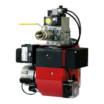
Page 10: Description Stg 146
Ignition electrode Air adjustment Transformer Air damper Inner assembly adjustment Fixing lange Front part fan housing Motor Rear part fan housing Electric connection Connection MultiBloc Ionisation electrode Air pressure switch MultiBloc Inner assembly Shielding arrangement fan housing Brake plate Bentone... -
Page 11: General Instruktions
Adjust the burner to appr. 20% excess air in accordance with the table. Check the lue gas temperature. Calculate the eficiency. Check also the actual gas volume on the gas meter so that the correct input is achieved. 172 515 03 2018-01-02 Bentone... -
Page 12: Installation
If not, use the connectors included. (Refer to connection under Electric equipment) If an electric connection other than the one recommended by Enertech is used, a risk of damage and injury can arise. 172 515 03 2018-01-02 Bentone... -
Page 13: Skeleton Diagrams
Gas pressure switch, maxi Main valve Safety valve Valve proving system Air pressure switch Gas burner control Pos. 5b, 7: Components not required according to EN 676. Required over 1200 kW according to EN 676. 172 515 19 2018-01-08 Bentone... -
Page 14: Mounting On The Boiler
Ensure that the union nut, ball valve and tubing make it easy to remove the burner for inspection and service. Check the gas tightness. 172 515 20 2018-01-08 Bentone... -
Page 15: Inspection Of Gas Nozzle Before Commissioning
At the end of the safety time (2-3 sec.) the gas control locks out. The solenoid valve and the motor will be "dead". Remove the link from the gas pressure switch after the test is inished. 172 515 21 2018-01-08 Bentone... -
Page 16: Gas Nozzle
4.9 Gas nozzle Inner assembly Natural, LPG Natural gas Bentone... -
Page 17: Multiblock Mb-Zrdle 405-412
2. Knob for adjustment of stage 1 Turn to the left = the start gas l ow is Test nipple, pressure after governor increased. Test nipple for nozzle pressure Filter Fixing l ange Ball valve 172 515 11 2018-01-03 Bentone... - Page 18 Turn to the right = the outlet pressure is increased Turn to the left = the outlet pressure is reduced Adjustment of start gas low Adjustment of governor Multi-bloc MB-ZRDLE 405-420 Flow adjustment 172 515 11 2018-01-03 Bentone...
- Page 19 5.4.1 Pressure taps 1,2,3,4,5 1/8 screwed sealing plug 5.4.2 Electrical connection S 20/S 50 172 515 11 2018-01-03 Bentone...
-
Page 20: Setting The Burner
Hower, study the sections dealing with adjustments of multi-bloc, combustion air and combustion head. Open the ball valve and switch on the main switch. If the burner starts the actual adjustment can be made. 172 515 22 2018-01-08 Bentone... - Page 21 The adjustment of the position of the brake plate affects the air low. It is therefore always necessary to make a ine adjustment of the air by means of the adjustment device of the burner. Gas quality max. CO lambda 1,2 Natural gas 10,0 11,9 11,5 13,9 Bentone...
- Page 22 Adjustment of inner assembly Air adjustment Control of burner head Bentone...
-
Page 23: Setting The Air Pressure Switch
This is to ensure the reliable function of the burner. If breakdowns or interruptions occur, the air pressure switch is probably set to a too narrow position. Fit the protective cover, screw (Y). Bentone... -
Page 24: Setting The Min. Gas Pressure Switch
The tolerance on the scale for the min. gas pressure switch is approx. ±15%. Open the ball valve. Remove the pressure gauge and close the pressure outlet (X). Check the gas tightness. Fit the protective cover, screw (Y). Bentone... -
Page 25: Recommended Excess Air When Using Default Setting
Lower heat value Hu at normal state 15°C and 1013.25 mbar EN676 Grade of gas kWh/Nm MJ/Nm kcal/Nm Natural gas 34.02 8126 Natural gas 29.25 6986 Propane 24.6 88.00 21019 Butane 32.5 116.09 27728 172 515 27 2018-01-11 Bentone... - Page 26 Temperature of gas at the gas meter [°C] Barometer reading [mbar] Pressure of gas at the gas meter [mbar] Factor calculated for multiplication with low in Nm /h to arrive at actual low in Nm Actual low · 273+T 1013.25 Bentone...
-
Page 27: Calculating The Quantity Of Gas Supplied
= Time for a certain quantity of gas consumed by the burner. M = Quantity of gas consumed. V = Actual gas low Calculation example: t = 1 min 10 s M = 100 dm (litre) 0.1 m 1000 0.0194 h 3600 ≈ 5.1 m 0.0194 Bentone... -
Page 28: Flame Monitoring And Ionisation Current Check
Min. DC 1.5 µA Required current to ensure Min. DC 3 µA detection Possible detection current Max. DC 20 µA Operational indicator lamp <5 µA DC lashes green Operational indicator lamp >5 µA DC shines green 172 615 02 2018-01-02 Bentone... -
Page 29: Uv-Detector
AGQ3...A27 is mandatory. Correct functioning of aged UV cells can be checked as UV test with a higher supply voltage across the UV cell after controlled shutdown until terminal 3 ON. Connection diagram Measuring circuit for measuring the UV lame current Measurement made at the lame detector QRA… Bentone... -
Page 30: Handing Over Of The Installation
• Is the circulation pump in operation? • Is there a supply of fresh air to the installation? • If integral components are of a different make from what is stated in this manual, see the enclosed loose-leaf. 172 615 04 2018-01-02 Bentone... -
Page 31: Electric Equipment
Signals must be in different harnesses for safety reasons. Safety system as door switches, water level, pressure, temperature and other safety limiters must be installed in safety loop according to process. 172 615 05 2018-01-02 Bentone... -
Page 32: Wiring Diagram Lme
8.2 Wiring diagram LME Bentone... -
Page 33: List Of Components
The operation of the burner can now be stopped with the control switch or thermostat If the gas burner control is blocked Red light in the gas burner control is lit. The burner is restarted by pushing the reset button Bentone... -
Page 34: Control Program At Faults; Fault Mode Indicator Lme
(waiting period ≥ 10 s) 8.4.1.2 Limiting of starting repetitions LME 11... has a function with start repetition if the lame is not created at start or disappears during operation.. LME 11... allows max. three repetitions during continuous starting cycle. Bentone... - Page 35 3 s. To go back to the normal position, press and hold the reset button longer than 3 s. If the gas burner control is in the alarm position, it is reset by pressing the reset button 0.5...3 s. Bentone...
-
Page 36: Troubleshooting
Replace solenoid valve terminals, or entire valve No power to solenoid valve Check the connection No electrical connection through air pressure gauge Check the air pressure gauge’s settings and functions Ignition load incorrectly set Increase/decrease gas supply Reduce airlow 172 615 06 2018-01-10 Bentone... - Page 37 Incorrectly set or faulty air sensor Check the settings and reset, or replace Ignition electrode overload Replace Burner control ambient temperature too high Insulate for heat, Max. 60 ° Ignition spark too weak Check the transformer Poor combustion Poor draught conditions Check the chimney Bentone...
- Page 38 Flame at incorrect angle due to combustion head out of position Check the combustion head and readjust Condensation build up in boiler and chimney Flue gas temperature too low or gas volume too low Raise the lue gas temperature by increasing gas volume Insulate the chimney Bentone...
-
Page 39: General Instructions For Gasburners
11. General instructions for gasburners 11.4.1 Installation Follow standards and instructions applicable to the Check that the burner is adapted to the gas quality in installation of gas burners question Ensure that the electric installation is made in accordance Check that the input pressure of the gas is correct with existing regulations Check that the dampers of the boiler are open Check that the fresh air intake of the boiler room is... - Page 40 Service- and inspection card Installation Boiler Name: Type: Eficiency kW: Address: Burner Type: Eficiency kW: Installed by: Date: Date gas/h Governor Fluegas Ionisation Pressure Eficiency temp current Fire Chimney room Measu- rement Before After °C µ A mbar mbar Small Flame Large Flame...
-
Page 41: Eu Declaration Of Conformity
11. EU Declaration of conformity Bentone Gasburners 172 905 04 2018-02-15... - Page 44 Enertech AB. P.O Box 309, SE-341 26 Ljungby. www.bentone.se, www.bentone.com...
Need help?
Do you have a question about the STG 146/1 and is the answer not in the manual?
Questions and answers