Advertisement
TECHNICAL SPECIFICATION
FEATURES
Protection Available
- Over Voltage
- Under Voltage
- Over Frequency
- Under Frequency
- Asymmetry
- Phase Loss
- Phase Sequence
3 digit bright LED display
Manual/Auto Reset option, Self powered
Time parameter: Power on delay, Recovery Time(Auto reset) Trip delay
INPUT SPECIFICATION
| Direct Voltage AC | 280 to 520V AC (L - L) 3Ø-3W 160 to 300V AC (L - N) 3Ø-4W |
| Frequency | 45.0 Hz to 65.0 Hz |
| Resolution | 1 Volt |
| Accuracy | Class 1.0 |
DISPLAY AND KEY
| Display | 3 digit, 1line, 7 seg, 0.4" RED LED |
| Keys | SET, INC, DEC/RST |
GENERAL SPECIFICATION
| Dimension (mm) | 75 (H) x 45 (W) x 110 (D) mm |
| Trip Setting | Under voltage: (260-520V AC,3Ø-3W), (160-300V AC,3Ø-4W) Over voltage: (260-520V AC,3Ø-3W), (160-300V AC,3Ø-4W) Under Frequency: 45.0 Hz To 65.0 Hz Over Frequency: 45.0 Hz To 65.0 Hz Phase Asymmetry: 2-30% |
| Time Parameter | Power ON Delay Time: 0 To 99 Sec. Trip delay Time: 0 To 999 Sec. Recovery Time: 0 To 99 Sec. |
OUTPUT SPECIFICATION
| Relay | 2 nos. |
| Relay Type | 1 C/O (NO-C-NC) |
| Rating | 1st Relay 10A, 230V AC 2nd Relay 5A, 230V AC |
AUXILIARY SUPPLY
Self powered, 30 VA MAX
ENVIRONMENT CONDITION
| Operating Temp. | 0°C to 55°C |
| Relative Humidity | UP to 95% RH (non-condensing) |
MECHANICAL INSTALLATION
| Front View(mm) | Side View(mm) |
 |
 |
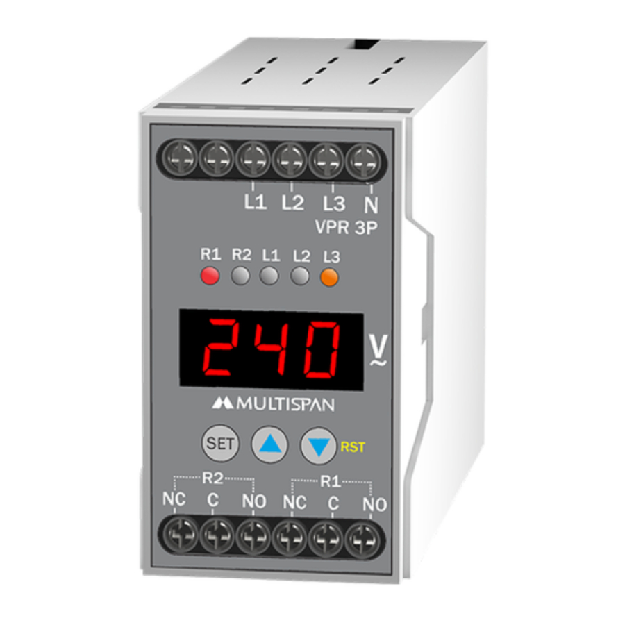
TERMINAL CONNECTION

KEY OPERATION
| FUNCTION | PRESS KEY |
| OPERATOR MODE | |
| To enter in parameter setting |  For 5 sec For 5 sec |
| To view individual phase voltage |  OR OR  |
| To Scroll & Hold Page | + |
| To reset the relay contact in manual mode after tripping | RST |
| PARAMETER SETTING MODE | |
| It is used to set parameter value and to be save & exit from menu | |
| To increment value in parameter setting | |
| To decrement value in parameter setting | RST |
DISPLAY PAGE

MECHANICAL INSTALLATION STEPS
- To install the instrument on a DIN rail, raise the clamp at the back of the instrument and place it on the rail. Now release the clamp, so the instrument fits on the DIN rail.
- Ensure proper fitting of the instrument by pulling it outwards.
- To remove the instrument raise the clamp to release it from the DIN rail.
- The equipment in its installed state must not come in close proximity to any heating source, caustic vapors, oil steam, or other unwanted process byproducts.
- Do not connect anything to unused terminals.
MAINTENANCE
- The equipment should be cleaned regularly to avoid blockage of ventilating parts.
- Clean the equipment with a clean soft cloth. Do not use isopropyl alcohol or any other cleaning agent.
- Fusible resistor must not be replaced by operator.
INSTALLATION GUIDELINES
- Do not allow pieces of metal, wire clippings, or fine metallic fillings from installation to enter the product or else it may lead to a safety hazard that may in turn endanger life or cause electrical shock to the operator.
- Circuit breaker or mains switch must be installed between power source and supply terminal to facilitate power 'ON' or 'OFF' function. However this mains switch or circuit breaker must be installed at convenient place normally accessible to the operator.
- Use and store the instrument within the specified ambient temperature and humidity ranges as mentioned in this manual.
SAFETY PRECAUTION
|
If all the equipment is not handled in a manner specified by the manufacturer, it might impair the protection provided by the equipment.
|
 All safety related codifications, symbols and instructions that appear in this operating manual or on the equipment must be strictly followed to ensure the safety of the operating personnel as well as the instrument.
 Read complete instructions prior to installation and operation of the unit.
WARNING GUIDELINES

Risk of electric shock.
- To prevent the risk of electric shock, power supply to the equipment must be kept OFF while doing the wiring arrangement. Do not touch the terminals while power is being supplied.
- To reduce electro magnetic interference, use wire with adequate rating and twists of the same of equal size shall be made with shortest connection.
- Cable used for connection to power source, must have a cross section of 1mm or greater. These wires should have insulations capacity made of at least 1.5kV.
- A better anti-noise effect can be expected by using standard power supply cable for the instrument.
PARAMETER SETTING

Password 11: To Enable / Disable parameter (Over Voltage, Under Voltage, over Frequency, Under Frequency, Asymmetry, Phase loss, Phase sequence)
Password 37: To set Power on delay time, Trip delay Time, Reset Mode, Relay Fault Mode.

Password 73: Relay 1 Settings
Password 97: Relay 2 Settings
(Relay-1 & Relay-2 Settings: To Set Trip Value Of Over Voltage, Under Voltage, Over Frequency, Under Frequency, Asymmetry Percentage)

- If R2M (Relay-2 mode) is selected as R1 (Relay-1), all the setting done for Relay-1 will be automatically set for Relay-2.
- For Hold & Scroll Press
![]() +
+ ![]() key for 3 Sec.
key for 3 Sec.

FAULT MESSAGE

Specifications are subject to change, since development is a continuous process,
So for more updated operating information and Support,
Please contact our Helpline: 9978991474/76/82 or Email at service@multispanindia.com
Ver: 191201

Documents / ResourcesDownload manual
Here you can download full pdf version of manual, it may contain additional safety instructions, warranty information, FCC rules, etc.
Advertisement


Need help?
Do you have a question about the VPR 3P and is the answer not in the manual?
Questions and answers