
Related Manuals for GIGAIPC QBiX-DR-EHLA6412H-A1


Summary of Contents for GIGAIPC QBiX-DR-EHLA6412H-A1
- Page 1 QBiX-DR-EHLA6412H-A1 (DR-6412A-SI) Industrial Embedded System Quick Start Guide www.gigaipc.com...
-
Page 2: Copyright Notice
Beijer assumes no liabilities resulting from errors or omissions in this document, or from the use of the information contained herein. GIGAIPC reserves the right to make changes in the product design without notice to its users. www.gigaipc.com... -
Page 3: Acknowledgement
Core, Atom are trademarks of Intel Corporation • • ITE is a trademark of Integrated Technology Express, Inc. IBM, PC/AT, PS/2, and VGA are trademarks of International Business • Machines Corporation. All other product names or trademarks are properties of their respective owners. www.gigaipc.com... -
Page 4: Packing List
Terminal Blocks 1 x 10P (P/N: 25IO0-EC3810-D2R) SATA cable (P/N: 25CF4-500500-S9R) SATA power cable (P/N: 25CRI-190920-S9R) HDD screw M3x4L (P/N : 25984G-1C014-S00) If any of these items are missing or damaged, please contact your distributor or sales representative immediately. www.gigaipc.com... -
Page 5: About This Document
This User’s Manual contains all the essential information, such as detailed descriptions and explanations on the product’s hardware and software features (if any), its specifications, dimensions, jumper/ connector settings/definitions, and driver installation instructions (if any), to facilitate users in setting up their product. www.gigaipc.com... -
Page 6: Safety Precautions
Make sure the device is installed near a power outlet and is easily accessible. 10. Keep this device away from humidity. 11. Place the device on a solid surface during installation to prevent falls 12. Do not cover the openings on the device to ensure optimal heat dissipation. www.gigaipc.com... - Page 7 18. D O N O T L E AV E T H I S D E V I C E I N A N U N C O N T R O L L E D ENVIRONMENT WITH TEMPERATURES BEYOND THE DEVICE’S PERMITTED STORAGE TEMPERATURES (SEE CHAPTER 1) TO PREVENT DAMAGE. www.gigaipc.com...
-
Page 8: Fcc Statement
Skilled person have to pay special attention or take special protection. Only authorized by well trained professional person can access the restrict access location. (2) External metal parts are hot!! Before touching it, special attention or protection is necessary www.gigaipc.com... -
Page 9: Table Of Contents
FCC Statement ................8 High Temperature Warning ............8 Chapter 1 - Product Specifications Specifications ............... 14 Chapter 2 – QBiX-DR-EHLA6412H-A1 (DR-6412A-SI) Dimension ..............17 Dimension - including wall mount brackets....18 Getting Familiar with Your Unit........19 A) Wireless Module : How to safely install the Module (Wireless Module inclusion may vary based on local distribution) .............. - Page 10 SYS_PANEL (Front panel header) ........40 3.2.7 M2B (M.2 Slot, B-Key, NGFF 3052/3042) ......41 3.2.8 SODIMM (DDR4 SO-DIMM Slot) ........42 3.2.9 USB_V (Vertical USB2.0 connector) ......43 3.2.10 SATAPW (SATA power connector) ......... 44 3.2.11 SATA0 (SATA 6Gb/s Connector) ........45 www.gigaipc.com...
- Page 11 Introduction ..............58 The Main Menu............. 59 Advanced ..............60 4.3.1 TPM Configuration ............61 4.3.2 IT8786 Super IO Configuration ........63 4.3.3 Hardware Monitor ............64 4.3.4 S5 RTC Wake Settings ........... 65 4.3.5 CPU Configuration ............66 www.gigaipc.com...
- Page 12 4.3.6 SATA Configuration ............67 4.3.7 Network Stack Configuration ........68 4.3.8 Digital IO Port Configuration ........69 Chipset ................70 Security ................. 71 Boot ................74 Save & Exit ..............75 www.gigaipc.com...
-
Page 13: Chapter 1 - Product Specifications
Chapter 1 Chapter 1 - Product Specifications www.gigaipc.com... - Page 14 www.gigaipc.com...
-
Page 15: Specifications
Specifications System QBiX-DR-EHLA6412H-A1 (DR-6412A-SI) Dimension System Size : 160W x 118D x 62.6H(mm) Intel® Celeron® J6412 Processor 10nm, 4 cores, 4 threads, up to 2.60 GHz TDP 10W 1 x DDR4 SO-DIMM socket, Max. Capacity 32 GB Memory Support Single Channel DDR4 3200 MHz memory modules Ethernet 2 x GbE LAN Ports (Intel®... - Page 16 System QBiX-DR-EHLA6412H-A1 (DR-6412A-SI) 1 x GPIO (8 bits) 1 x 3-pin Terminal Block Side I/O 2 x COM Ports (RS-232/422/485 & RI/5V/12V) 2 x External Antenna Holes (Optional) Power +9V~36VDC (Full Range) Operating temperature: 0°C to 50°C Operating humidity: 0-90% (non-condensing) Operation Non-operating temperature: -40°C to 85°C...
-
Page 17: Chapter 2 - Qbix-Dr-Ehla6412H-A1 (Dr-6412A-Si)
Chapter 2 Chapter 2 – QBiX-DR-EHLA6412H-A1 (DR-6412A-SI) www.gigaipc.com... -
Page 18: Dimension
Dimension www.gigaipc.com... -
Page 19: Dimension - Including Wall Mount Brackets
Dimension - including wall mount brackets 116.7 NOTE : The wall mount brackets are the optional parts, and will not be shipped with system. Above dimension drawing including wall mount backets is for reference only. www.gigaipc.com... -
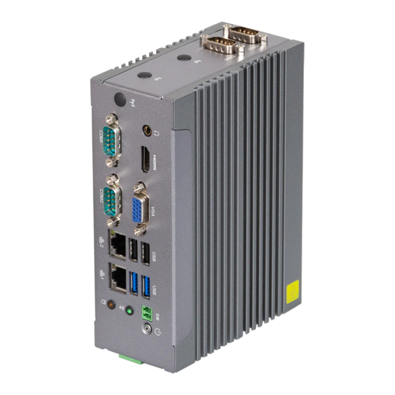
Page 20: Getting Familiar With Your Unit
BIOS selection. (please refer to Page 63) [Front Side] [Side IO Top Side] 2 x COM Ports (RS-232/422/485 & RI/5V/12V) Din Rail 2 x External Antenna Holes *NOTE : COM3 & COM4 RI/5V/12V setting are supported by jumper setting. (please refer to Page 38) www.gigaipc.com... - Page 21 * 接上電源前 ,請確實將機殼完整鎖附 。 [Bottom PCB Side] Information A M.2 2230 E-Key connector B M.2 3052/3042 B-Key connector C M.2 2280 M-Key connector D DDR4 SO-DIMM Slot E USB 2.0 Vertical connector www.gigaipc.com...
-
Page 22: A) Wireless Module : How To Safely Install The Module (Wireless Module Inclusion May Vary Based On Local Distribution)
Module (Wireless Module inclusion may vary based on local distribution) Carefully insert the wireless module into Lock the screw in the middle. the M.2 slot 青山依舊在,幾度夕陽紅。慣看秋月春風。一 壺濁酒喜相逢,浪花淘盡英雄。是非成敗轉頭 Install the antenna on the left side of the connection wireless module down. www.gigaipc.com... -
Page 23: B) 5G Module Installation: How To Safely Install The Module (5G Module Inclusion May Vary Based On Local Distribution)
B) 5G module Installation: How to safely install the module (5G Module inclusion may vary based on local distribution) Remove the screw from the screw hole. Carefully insert the 5G module into the slot, and secure with the screw. www.gigaipc.com... -
Page 24: C) M.2 Ssd Installation: How To Safely Install The M.2 2280 Ssd
C) M.2 SSD Installation: How to safely install the M.2 2280 SSD Remove the screw from the screw hole (Loca�on : MSO9) Carefully insert the M.2 SSD into the slot, and secure with the screw. www.gigaipc.com... -
Page 25: D) Memory Installation: Ddr4 So-Dimm
D) Memory Installation: DDR4 SO-DIMM SO-DIMM www.gigaipc.com... -
Page 26: Hdd Installation
HDD Installation www.gigaipc.com... -
Page 27: Antenna Installation (Antenna Inclusion May Vary Based On Local Distribution)
Antenna Installation (Antenna inclusion may vary based on local distribution) www.gigaipc.com... -
Page 28: Din Rail Bracket Installation
Din Rail Bracket Installation BRIX IoT. VESA BRIX VESA VESA www.gigaipc.com... -
Page 29: Wall Mount Bracket Installation
Suggest screws as below for different type of surface. Concrete wall Machine Wooden wall Electric drill Wall anchors Self-tapping screw Self-tapping screw Machine screw ST3.2 x 30mm ST3.2 x 25mm ST3.2 x 25mm M3 x 10mm pan head, with Spring washer + flat washer www.gigaipc.com... -
Page 30: Cable Pin-Define
2.11 Cable Pin-define 1. DB9 COM (25CF8-250620-S9R) RS-422 RS-485 DB9 Pin RS-232 Full Duplex Half Duplex TXD- TXD+ RXD+ RXD- 2. DBP DIO (25CR5-100701-S9R) DBP DIO Pin Pin Name GPIO-output_1 GPIO-input_1 GPIO-output_2 GPIO-input_2 GPIO-output_3 GPIO-input_3 GPIO-output_4 GPIO-input_4 www.gigaipc.com... -
Page 31: Safety And Regulatory Information
At the end of its serviceable life, this product should not be treated as household or general waste. It should be handed over to the applicable collection point for the recycling of electrical and electronic equipment, or returned to the supplier for disposal. www.gigaipc.com... -
Page 32: Chapter 3 - Motherboard Pin Define
Chapter 3 Chapter 3 – Motherboard Pin Define www.gigaipc.com GIGAIPC reserves the right to modify or revise the content at anytime without prior notice. -
Page 33: Jumpers And Connectors
Jumpers and Connectors www.gigaipc.com GIGAIPC reserves the right to modify or revise the content at anytime without prior notice. - Page 34 * RI/5V/12V setting are supported by BIOS selection . LAN Connector (Top) USB_LAN2 USB 2.0 Connector (Bottom) LAN Connector (Top) USB_LAN1 USB 3.2 Gen 1 Connector (Bottom) www.gigaipc.com GIGAIPC reserves the right to modify or revise the content at anytime without prior notice.
- Page 35 Code Description Headphone Jack HDMI HDMI connector VGA Connector Remote Control connector PWR_SW PWR_BUTTON Power button with LED www.gigaipc.com GIGAIPC reserves the right to modify or revise the content at anytime without prior notice.
-
Page 36: Dc_In (Dc In 1X3-Pin Terminal Block)
3.2.1 DC_IN (DC IN 1x3-pin Terminal Block) DC_IN Connector Pin No. Definition CH_GND DCVIN www.gigaipc.com GIGAIPC reserves the right to modify or revise the content at anytime without prior notice. -
Page 37: Gpio_Cn (General Purpose Input/Output Header )
GPIO Connector Connector PN Vendor 725-81-12TW00 PINREX A2004WV-2X06P46 JOINT-TECH Definition Pin No GPIO-output_1 GPIO-input_1 GPIO-output_2 GPIO-input_2 GPIO-output_3 GPIO-input_3 GPIO-output_4 GPIO-input_4 SMBus Clock SMBus DATA www.gigaipc.com GIGAIPC reserves the right to modify or revise the content at anytime without prior notice. -
Page 38: Com3, Com4 (Serial Port Header, Rs-232/422/485 & Ri/5V/12V)
Full Duplex Half Duplex TXD+ TXD- RXD- — RXD+ — — — — — — — — — No Connect — — RI/5V/12V — — www.gigaipc.com GIGAIPC reserves the right to modify or revise the content at anytime without prior notice. -
Page 39: Jcom3, Jcom4 (Ri# Pin Ri#/5V/12V Select Jumper For Com3 & Com4 Port)
JCOM3/ JCOM4 Jumper Select Connector PN Vendor 220-97-03GB01 PINREX 1-2 Close: PH06N53BAZ000 HORNGTONG 5V (Power COM) 3-4 Close: RI (Stand COM) 5-6 Close: 12V (Power COM) www.gigaipc.com GIGAIPC reserves the right to modify or revise the content at anytime without prior notice. -
Page 40: At_Cn (At/Atx Mode Select Jumper)
220-96-03GB001K PINREX Pin No. Definition AT MODE Detect ATX MODE Jumper setting 1-2 Close : AT mode. 2-3 Close : ATX mode. (Default setting) www.gigaipc.com GIGAIPC reserves the right to modify or revise the content at anytime without prior notice. -
Page 41: Sys_Panel (Front Panel Header)
3.2.6 SYS_PANEL (Front panel header) Pin 1 System Panel Header Connector PN Vendor 85205-0470N ACES A1250WV-S-04PC JOINT-TECH Pin No. Definition +V3.3A_FUSE WIFI_LED www.gigaipc.com GIGAIPC reserves the right to modify or revise the content at anytime without prior notice. -
Page 42: M2B (M.2 Slot, B-Key, Ngff 3052/3042)
Definition GPP_RESET M2B_DET M2B_WAKE 3.3V M2B_DRP 3.3V WWAN_ 3.3V Disable2 USB3 RXn Connector PN Vendor USB3_RXp SIM_RST# 80149-8521 BELLWETHER SIM_CLK 2E0BC21-S85BB-7H FOXCONN USB3_TXn SIM_DATA www.gigaipc.com GIGAIPC reserves the right to modify or revise the content at anytime without prior notice. -
Page 43: Sodimm (Ddr4 So-Dimm Slot)
3.2.8 SODIMM (DDR4 SO-DIMM Slot) www.gigaipc.com GIGAIPC reserves the right to modify or revise the content at anytime without prior notice. -
Page 44: Usb_V (Vertical Usb2.0 Connector)
3.2.9 USB_V (Vertical USB2.0 connector) USB 2.0 connector Connector PN Vendor UB0112C-4FH9-4H FOXCONN UB0112C-4HH9-4F FOXCONN Pin No. Definition www.gigaipc.com GIGAIPC reserves the right to modify or revise the content at anytime without prior notice. -
Page 45: Satapw (Sata Power Connector)
3.2.10 SATAPW (SATA power connector) Pin 1 Hard Disk Power Connector Connector PN Vendor 743-81-04TW00 PINREX WF04Q2-3BJQ000 HORNGTONG Pin No. Definition www.gigaipc.com GIGAIPC reserves the right to modify or revise the content at anytime without prior notice. -
Page 46: Sata0 (Sata 6Gb/S Connector)
3.2.11 SATA0 (SATA 6Gb/s Connector) SATA Connector Connector PN Vendor WATF-07DBLBA1UW WINWIN Pin No. Definition www.gigaipc.com GIGAIPC reserves the right to modify or revise the content at anytime without prior notice. -
Page 47: Bat (Battery Cable Connector)
3.2.12 BAT (Battery cable connector) Pin 1 Battery Cable Connector Connector PN Vendor 85205-0270L ACES A1250WV-S-02PC JOINT-TECH Pin No. Definition 3.3V www.gigaipc.com GIGAIPC reserves the right to modify or revise the content at anytime without prior notice. -
Page 48: M2M (M.2 Slot, M-Key, Ngff2280)
SATA_TXn 3.3V SATA_TXp 3.3V M2_LED 3.3V Pin No. Definition Pin No. Definition 3.3V SUSCLK 3.3V 3.3V 3.3V 3.3V 3.3V Connector PN Vendor 80159-8521 BELLWETHER www.gigaipc.com GIGAIPC reserves the right to modify or revise the content at anytime without prior notice. -
Page 49: M2E (M.2 Slot, E-Key, Ngff2230)
3.3V WIFI_Disable# USBp 3.3V USBn WiFi_LED BT_LED 3.3V 3.3V Connector PN Vendor APCI0095-P002A LOTES Pin No. Definition Pin No. Definition 80152-8521 BELLWETHER PCIE_TXp PCIE_TXn www.gigaipc.com GIGAIPC reserves the right to modify or revise the content at anytime without prior notice. -
Page 50: Com1
— RXD- — — — — — — — — — *NOTE : RI/5V/12V are supported by BIOS selection. (please refer to Page 63) www.gigaipc.com GIGAIPC reserves the right to modify or revise the content at anytime without prior notice. - Page 51 RXD- — — — — — — — — — * NOTE : RI/5V/12V are supported by BIOS selection. (please refer to Page 63) www.gigaipc.com GIGAIPC reserves the right to modify or revise the content at anytime without prior notice.
- Page 52 Definition BI_DA+ BI_DC- BI_DA- BI_DB- BI_DB+ BI_DD+ BI_DC+ BI_DD- State Description Orange On 1Gbps data rate Green On 100Mbps data rate 10Mbps data rate www.gigaipc.com GIGAIPC reserves the right to modify or revise the content at anytime without prior notice.
-
Page 53: Connector (Bottom))
BI_DD- State Description USB3_RX1n USB3_RX2n Orange On 1Gbps data rate USB3_RX1p USB3_RX2p Green On 100Mbps data rate USB3_TX1n USB3_TX2n 10Mbps data rate USB3_TX1p USB3_TX2p www.gigaipc.com GIGAIPC reserves the right to modify or revise the content at anytime without prior notice. -
Page 54: Hp (Headphone Jack)
3.2.19 HP (Headphone Jack) www.gigaipc.com GIGAIPC reserves the right to modify or revise the content at anytime without prior notice. -
Page 55: Hdmi (Hdmi Connector)
3.2.20 HDMI (HDMI Connector) HDMI Connector Pin No. Definition Pin No. Definition TX2p CLKn TX2n TX1p TX1n TX0p Hot Plug TX0n Detect CLKp www.gigaipc.com GIGAIPC reserves the right to modify or revise the content at anytime without prior notice. -
Page 56: Vga (Db-15 Vga Connector)
3.2.21 VGA (DB-15 VGA Connector) D-sub Connector Pin No. Definition Pin No. Definition Green Blue DDCSDA HSYNC VSYNC DDCSCL www.gigaipc.com GIGAIPC reserves the right to modify or revise the content at anytime without prior notice. -
Page 57: Pwr_Sw (Remote Control Connector)
Power Switch Power Switch Remote Control connector Pin No. Definition PWRBTSW 3.2.23 PWR_BUTTON (Power button with LED) Power Button with LED Power Button with LED www.gigaipc.com GIGAIPC reserves the right to modify or revise the content at anytime without prior notice. -
Page 58: Chapter 4 - Bios
Chapter 4 Chapter 4 – BIOS www.gigaipc.com... -
Page 59: Introduction
Execute command or enter the submenu Increase the numeric value or make + changes Decrease the numeric value or make – changes General Help Previous Values Load Optimized Defaults Settings Save changes & Exit the BIOS Setup program Exit the BIOS Setup program www.gigaipc.com... -
Page 60: The Main Menu
ME FW version Shows TXE firmware version Set the Date for the system System Date (Format : Week - Month - Day - Year) Set the time for the system System Time (Format : Hour - Minute - Second) www.gigaipc.com... -
Page 61: Advanced
Advanced The Advanced menu is to configure the functions of hardware settings through submenu. Use arrow keys to move among the items, and press <Enter> to access into the related submenu. www.gigaipc.com... -
Page 62: Tpm Configuration
4.3.1 TPM Configuration Use TPM Configuration submenu to choose TPM interface. Item Description TPM Device PTT (Default setting) Selection www.gigaipc.com... - Page 63 Item Description Security Device Enabled : Enables TPM feature (Default setting) support Disabled : Disables TPM feature Item Description None : No execution will be conducted (Default setting) Pending operation TPM clear : Set to clear data on TPM www.gigaipc.com...
-
Page 64: It8786 Super Io Configuration
Enabled : Enables allows you to configure the serial port settings Disabled : if Disabled, displays no configuration for the serial port Device settings : Display the specified Serial Port base I/O address and IRQ Serial Port 4 Configuration COM Port Mode : Choose RS-232, RS-422, or RS-485 feature www.gigaipc.com... -
Page 65: Hardware Monitor
4.3.3 Hardware Monitor Item Description CPU temperature Shows current CPU temperature System temperature Shows current system temperature www.gigaipc.com... -
Page 66: S5 Rtc Wake Settings
Enable or Disable System to wake on a specific time. Wake system Disabled : Disables system to wake on a specific time (Default setting) from S5 Fixed Time : Enables system to wake on a specific time (Format : hr : min : sec) www.gigaipc.com... -
Page 67: Cpu Configuration
CPU C-states Enabled : Enables C states (Default setting) Disabled : Disables C states CPU will adjust frequency depends on it's loading. CPU P-states Enabled : Enables CPU P states function (Default setting) Disabled : Disables CPU P states function www.gigaipc.com... -
Page 68: Sata Configuration
4.3.6 SATA Configuration Item Description SATA Mode AHCI : Configures the SATA controllers to AHCI mode. (Default setting) Selection Serial ATA Port 0 shows 2.5" SATA HDD/SSD information M.2 Port shows M.2 SATA interface SSD information www.gigaipc.com... -
Page 69: Network Stack Configuration
When Network stack is enabled : Ipv4 PXE Support Disabled : Disables Ipv4 PXE Support Enabled : Enables Ipv4 PXE Support When Network stack is enabled : Ipv6 PXE Support Disabled : Disables Ipv6 PXE Support Enabled : Enables Ipv6 PXE Support www.gigaipc.com... -
Page 70: Digital Io Port Configuration
Enabled : If Digital IO Output value/level is modified in OS, they will be memorized and kept. SOGPO_1 (Pin 1) SOGPI_1 (Pin 2) SOGPO_2 (Pin 3) SOGPI_2 (Pin 4) Configure Digital IO Input or Output values for each pin. SOGPO_3 (Pin 5) SOGPI_3 (Pin 6) SOGPO_4 (Pin 7) SOGPI_4 (Pin 8) www.gigaipc.com... -
Page 71: Chipset
Enable/Disable XHCI Hand-off function XHCI Hand-off Enabled : Enables XHCI Hand-off function (Default setting) Disabled : Disables XHCI Hand-off function Enable/Disable BIOS Lock function BIOS Lock Enabled : Enables BIOS Lock function (Default setting) Disabled : Disabled BIOS Lock funtion www.gigaipc.com... -
Page 72: Security
To set up Administrator's password Administrator Minimum length : 3 Password Maximum length : 20 To set up User's password User Password Minimum length : 3 Maximum length : 20 Secure Boot Press <Enter> to configure the advanced items www.gigaipc.com... - Page 73 No : Cancel to restore factory settings Reset To Setup Yes : Agree to setup mode Mode No : Cancel to setup mode Enables expert users to modify Secure boot policy variables without full Key Management authentication Press <Enter> to configure the advanced items www.gigaipc.com...
- Page 74 'UEFI CA' from database from DB No : Cancel to remove 'UEFI CA' from database Restore DB variables to fac tor y Restore DB defaults defaults Yes : Agree to restore DB defaults No : Cancel to restore DB defaults www.gigaipc.com...
-
Page 75: Boot
Enabled : Enables Full screen LOGO Show on POST screen LOGO Show Disabled : Disables Full screen LOGO Show on POST screen (Default setting) Boot Option #1 Shows the information of the storage that be installed in the system Boot Option #2 Choose/set the boot priority www.gigaipc.com... -
Page 76: Save & Exit
Yes : Agree to load optimized defaults No : Cancel to load optimized defaults Enable/Disable Me FW image re-flash function Me FW Image Enabled : Enables Me FW image re-flash function Re-Flash Disabled : Disables Me FW image re-flash function (Default setting) www.gigaipc.com...
Need help?
Do you have a question about the QBiX-DR-EHLA6412H-A1 and is the answer not in the manual?
Questions and answers