Table of Contents
Advertisement
Quick Links
FU-601
Soldering iron unit
Instruction Manual
Thank you for purchasing the HAKKO FU-601 soldering iron unit.
Please read this manual before operating the HAKKO FU-601.
Keep this manual readily accesible for reference.
TABLE OF CONTENTS
........................................................ 22
Visit us at www.TestEquipmentDepot.com
●
●
...................................................... 1
................................................. 1
....................................................... 3
...................................................... 5
......................................................... 8
......................................12
...................................................15
..................................17
...........................................18
...........................19
.............................................. 22
99 Washington Street
Melrose, MA 02176
Phone 781-665-1400
Toll Free 1-800-517-8431
............... 2
................. 21
Advertisement
Table of Contents

Subscribe to Our Youtube Channel
Related Manuals for Hakko Electronics FU-601


Summary of Contents for Hakko Electronics FU-601
-
Page 1: Table Of Contents
99 Washington Street Melrose, MA 02176 Phone 781-665-1400 Toll Free 1-800-517-8431 Visit us at www.TestEquipmentDepot.com FU-601 Soldering iron unit Instruction Manual ● Thank you for purchasing the HAKKO FU-601 soldering iron unit. Please read this manual before operating the HAKKO FU-601. Keep this manual readily accesible for reference. ● TABLE OF CONTENTS 1. PACKING LIST ............1 2. SPECIFICATIONS ..........1 3. WARNINGS, CAUTIONS AND NOTES .... -
Page 2: Packing List
1. PACKING LIST Please check to make sure that all items listed below are included in the package. HAKKO FU-601 .............1 Iron cable (5m) ............1 HAKKO FU-6001 (HAKKO FU-6002) ....1 Connecting cable ..........1 Flux protector ............1 Power cord ............1 Iron unit fixing assembly ........1... -
Page 3: Warnings, Cautions And Notes
● Do not modify the HAKKO FU-601. ● Use only genuine Hakko replacement parts. ● Do not allow the HAKKO FU-601 to become wet, or use it with wet hands. ● Be sure the work area is well ventilated. Soldering produces smoke. -
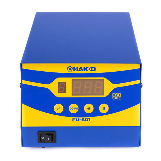
Page 4: Part Names
4. PART NAMES ● HAKKO FU-601 Preset number display Setting display Control buttons Power switch Fuse Jack ( Error out *) Connecting cable connector Receptacle * Error out circuit 30V, less than 100 mA Iron GND... - Page 5 ● HAKKO FU-6002 Positioning screw ① Flux protector Tip lock screw Fixing screw Positioning screw ② CAUTION Do not touch any screws than the hexagon socket head cap screws described in this manual.
-
Page 6: Initial Setup
Pin No. Signal name Function Iron GND Outgoing data Incoming data Recommended Iron_Ready signal connection diagram Iron_Ready HAKKO FU-601 Ready signal Iron_GND HAKKO FU-601 GND Iron_Vcc Iron_GND Iron_Vcc HAKKO FU-601 Vcc (5V) Iron_Ready External equipment ● How to attach the tip... - Page 7 ● How to position the tip 1. To turn the shaft of the tip, loosen the positioning screw ①. To move the soldering iron in the longitudinal direction, loosen the positioning screw ②. Tighten the screws after determining the tip position balancing with your work object. ①...
- Page 8 4. Place the HAKKO FU-6002 on the iron unit fixing assembly and tighten the two screws. Tighten ● Installing the iron to the feeder unit Tighten the feeder unit set screws as shown in the figure below. Now you can install the HAKKO FU-6002 to the feeder unit. size:M3×30 ●...
-
Page 9: Operation
6. OPERATION The HAKKO FU-601 has the following four control buttons. When press for less than one second, enters preset number selection screen. When press and hold for at least one second, enters preset temperature changing screen. Increase the value in the appropriate display window. - Page 10 Changing temperature setting CAUTION The temperature range is from 50 to 500℃. ( 120 to 940℉) ●If you enter a value outside the temperature setting range, the display returns to the hundreds digit, and you have to enter a correct value. Example:350 to 400℃...
- Page 11 Selecting the preset number You can call up the preset temperature by pressing the buttons. Initial preset temperature is 0:300℃, 1:350℃, 2:375℃, 3:400℃, 4:450℃ and 5:500℃. Example:preset number0 (300℃) to No.3 (400℃) 1. Press the button once. Preset number display will begin to flash. 2.
- Page 12 Entering the tip offset value Example:If the measured temperature is 410℃ and set temperature is 400℃, the difference is -10℃. (need to decrease by 10℃) So, enter the figure which 10 is deducted from present offset value. 1. Press and hold the button for at least one second.
-
Page 13: Parameter Setting
7. PARAMETER SETTING Parameter name Parameter number Value Initial value Temperature display ℉( )/℃( ) ℃ Low temperature error setting 30 - 300℃ (54 - 540℉) 300℃ Buzzer setting OFF( )/ON( ) ON ( ) (S-E sound , C-E sound) Buzzer setting OFF( )/ON( ) ON ( ) (set temperature achieving alert) Power-mode setting High power( )/Normal power( ) High power( ) Password lock setting Open ( ) / Partial ( ) / Restricted ( ) Open( ) - Page 14 ● 05:S-E, C-E buzzer sound setting In the buzzer setting mode, which sets whether to sound the buzzer when a sensor error or soldering iron error occurs, either is displayed. :The buzzer does not sound when error occurs. :The buzzer sounds when error occurs. ●...
- Page 15 ● 20:Ready signal delay time You can set the delay time after the HAKKO FU-601 gets ready (ie., the temperature of the tip reaches the set value) until the Iron Ready signal becomes on. Delay time setting range : 0 - 60 sec.
-
Page 16: Maintenance
● 24:Tip setting TX1 series of the tip (for the HAKKO FU-600) can be connected to the HAKKO FU-601. CAUTION Be sure to selected the tip of the kind used when you use a different kind of the tip. Failure to do this may result in a tip temperature that is much higher or lower than the previous one. - Page 17 5. Inspecting and cleaning the tip This procedure, if followed daily, will materially add to tip life. a. Set the temperature to 250℃ (482℉). b. When the temperature stabilizes, clean the tip and check the condition of the tip. If the tip is badly worn or deformed, replace it. c.
-
Page 18: Checking Procedure
9. CHECKING PROCEDURE WARNING Unless otherwise directed, carry out these procedures with power switch OFF and the power UNPLUGGED. ■ Check for a broken heater or sensor Verify the electrical integrity of the heater and sensor. Measure the resistance of the heater and sensor while at room temperature (15℃ to 25℃; 59℉ to 77℉). -
Page 19: Error Messages
10. ERROR MESSAGES CAUTION If any of the errors occur, the Ready signal output to the HAKKO FU-500 will be “Not Ready”. ● Sensor error When there is possibility that a failure has occured in the sensor or heater (including the sensor circuit), is displayed and a buzzer sounds. -
Page 20: Trouble Shooting Guide
11. TROUBLE SHOOTING GUIDE ●The unit does not operate when the power switch is turned ON. CHECK : Is the power cord and/or the connection plug disconnected? ACTION : Connect it. CHECK : Is the fuse down? ACTION : Investigate why the fuse blew and then replace the fuse. If the fuse blows again, send the unit in for repair. - Page 21 ●The low-temperature alarm tolerance error is displayed. CHECK : Is the tip too small for the items to be soldered? ACTION : Use a tip with a larger thermal capacity. CHECK : Is the setting value for the low-temperature alarm tolerance too low? ACTION ...
-
Page 22: Dimensional Outline Drawing
12. DIMENSIONAL OUTLINE DRAWING HAKKO FU-6001 connected to the feeder unit Back view of A HAKKO FU-6002 connected to the feeder unit Back view of A’ HAKKO FU-6001/6002 disconnected 2 mounting holes Φ4.2 Through Φ8 Counterbore 5 Deep ※ 104 (※ 108) ... -
Page 23: Exploded View
13. EXPLODED VIEW ● HAKKO FU-601 ● HAKKO FU-6001 ● HAKKO FU-6002 14. PARTS LIST Item No. Part No. Part Name Specifications ① ② ③ FU6001-01X HAKKO FU-6001 with Flux protector ① FU6002-01X HAKKO FU-6002 with Flux protector ② BX1027 Flux protector ③... - Page 24 TIP STYLES 14.5 Unit:mm TX2-XD3 Shape-3XD TX2-XD4 Shape-4XD TX2-XD6 Shape-6XD TX2-XBCR3 Shape-3XBCR TX2-XBCR4 Shape-4XBCR TX2-XBCR6 Shape-6XBCR TX2-XDR3 Shape-3XDR TX2-XDR4 Shape-4XDR TX2-XDR6 Shape-6XDR TX2-XRK Shape-XRK 99 Washington Street Melrose, MA 02176 Phone 781-665-1400 Toll Free 1-800-517-8431 Visit us at www.TestEquipmentDepot.com 2018.2 © 2017-2018 HAKKO Corporation. All Rights Reserved. MA02900XZ180202...
Need help?
Do you have a question about the FU-601 and is the answer not in the manual?
Questions and answers