Krone Big Pack 890 HS Original Operating Instructions

Krone Big Pack 890 HS Original Operating Instructions

Big pack baler
Table of Contents

Advertisement

Quick Links

< v > T - T y p 1 < / v >
BiG Pack 890 HS/XC
BiG PACK 1270 HS/XC
< v > T - T y p 2 < / v >
BiG PACK 1290 HS/XC
< v > T - T y p 3 < / v >
< v > T - T y p 4 < / v >
BiG PACK 1290 HDP / XC
< v > T - T y p 5 < / v > < / v >
< v > T - T y p 6 < / v > < / v >
(< v > T - a b M a s c h . - N r . < / v >
from serial
no.< / v >
< v > T - B e s t e l l - N r . < / v >
Order
no.< / v >
: 150 000 137 00 en
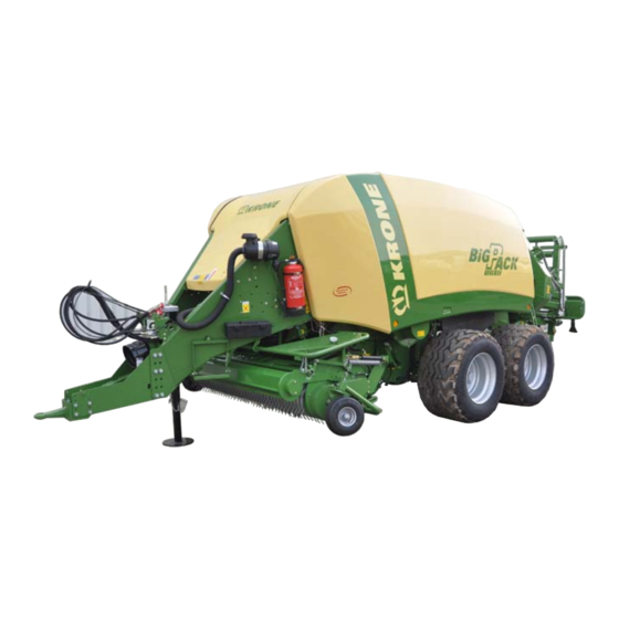
< v > B - T i t e l b i l d < / v >
BiG PACK Baler
< / v >
< / v >
< / v >
: 819 240)
HS< / v >
< / v >
17.03.2011

Advertisement

Table of Contents
loading
Need help?

Need help?

Do you have a question about the Big Pack 890 HS and is the answer not in the manual?

Questions and answers

Subscribe to Our Youtube Channel

Summary of Contents for Krone Big Pack 890 HS

  • Page 1 BiG PACK Baler < v > T - T y p 1 < / v > BiG Pack 890 HS/XC < / v > < v > T - T y p 2 < / v > BiG PACK 1270 HS/XC <...
  • Page 2 Big Pack 890 HS; Big Pack 1270 HS; Big Pack 1290 HS; Big Pack 1290 HDP HS Big Pack 890 HS XC; Big Pack 1270 HS XC; Big Pack 1290 HS XC; Big Pack 1290 HDP HS XC to which this declaration refers is in compliance with the relevant provisions of EC Directive 2006/42/EC (Machinery) and EC Directive 2004/108/EC (EMC) The signing Managing Director is authorised to compile the technical documents.
  • Page 3: Foreword

    Pos: 4.2 /BA/Vorwort/Großpackenpressen/Verehrter Kunde BiG Pack @ 17\mod_1236162357058_78.doc @ 201236 Dear Customer! By purchasing your BiG PACK baler, you have acquired a quality product from KRONE. We are grateful for the confidence you have invested in us in buying this machine.
  • Page 4: Table Of Contents

    Foreword Pos: 6 /BA/Inhaltsverzeichnis Sprachenneutral @ 10\mod_1221574899104_0.doc @ 135495     Foreword ..............................3     Introduction ............................13 Purpose of Use ..........................13     Validity ............................. 13     2.2.1 Contact ............................13     Identification Plate ........................... 14  ...
  • Page 5: Foreword

    Foreword 3.11 Safety Instructions on the Machine ....................38     3.12 Introduction ............................39     3.13 Position of the Adhesive Safety Stickers on the Machine ............... 40     3.14 Position of the General Information Labels on the Machine ............42  ...
  • Page 6     6.4.2 Wheel chocks ..........................79         KRONE ISOBUS-Terminal CCI 100 ..................... 80 Installing the terminal into cabin ...................... 81     ISOBUS short cut button ......................... 82     7.2.1 Connecting the terminal (on tractors with integrated ISOBUS system) ........84  ...
  • Page 7 Connection terminal to tractor ....................148     8.1.2 Connection tractor to machine ....................148     Differing functions to KRONE ISOBUS terminal CCI ..............149     ISOBUS „Auxiliary“-function (AUX) ....................151     8.3.1 Example of a joystick assignment for Fendt (default setting) ............ 152  ...
  • Page 8 Foreword 9.11.2 Twine motion indicator upper twine (double knotter) ............. 169     9.11.3 Initiate the tying process manually ..................170     9.12 Drives ............................. 171     9.12.1 Main drive ..........................171     9.13 Feed packer drum drive ......................... 172  ...
  • Page 9 Foreword 10.8.5 Setting of twine retainer ......................199     10.8.5.1 Setting the holding force of the twine retainer (6) ............200     10.8.6 Setting of blade lever (single knotter) ..................201     10.8.7 Double knotter ........................202  ...
  • Page 10 Foreword 11.3.2 Lifting ............................. 225     11.4 Tightening Torques ........................226     11.5 Tightening Torques (Countersunk Screws) ................... 227     11.6 Cleaning ............................228     11.7 Tyres .............................. 228     11.7.1 Checking and maintaining tyres..................... 229  ...
  • Page 11 Foreword 13.5 Lubricating the rollers for the blade lever ..................255     13.6 Lubrication points ........................... 256     13.6.1 Lubrication points BiG PACK 890 (XC), 1270 (XC), 1290 (XC) ..........256     13.6.2 Lubrication points BiG PACK 1290 HDP (XC) ............... 258  ...
  • Page 12 Foreword Pos: 7 /BA/-----Seitenumbruch------ @ 0\mod_1196175311226_0.doc @ 4165...
  • Page 13: Introduction

    BiG PACK 1290 HDP / XC. Pos: 8.7 /Überschriften/Überschriften 3/A-E/Ansprechpartner @ 0\mod_1195569394286_78.doc @ 839 2.2.1 Contact Pos: 8.8 /Adressen/Adresse Maschinenfabrik KRONE Spelle @ 0\mod_1195568531083_78.doc @ 734 Maschinenfabrik Bernard Krone GmbH Heinrich-Krone-Strasse 10 D-48480 Spelle (Germany) Telephone: + 49 (0) 59 77/935-0 (Head Office) Fax.: + 49 (0) 59 77/935-339 (Head Office)
  • Page 14: Identification Plate

    Authentic KRONE spare parts and accessories authorised by the manufacturer help to ensure safety. The use of spare parts, accessories and other devices which are not manufactured, tested or approved by KRONE will result in the revoking of the liability for damages resulting thereof.
  • Page 15: Intended Use

    Introduction Pos: 8.14.1 /Überschriften/Überschriften 2/A-E/Bestimmungsgemäßer Gebrauch @ 0\mod_1196401545090_78.doc @ 7728 Intended Use Pos: 8.14.2 /BA/Einleitung/Bestimmungsgemäßer Gebrauch/Grosspackenpresse/Bestimmungsgemäßer Gebrauch BiG Pack @ 17\mod_1236169306605_78.doc @ 201542 The Big Pack baler is built exclusively for customary use in agricultural work (intended use). Pos: 8.14.3 /BA/Einleitung/Bestimmungsgemäßer Gebrauch/Nicht bestimmungs gemäss @ 0\mod_1196401324340_78.doc @ 7690 Any use of the machine for other purposes is deemed not to be in accordance with intended use.
  • Page 16: Technical Data

    Introduction Pos: 8.16 /BA/Einleitung/Technische Daten @ 0\mod_1195566374865_78.doc @ 594 Technical data All information, illustrations and technical data in these operating instructions correspond to the latest state at the time of publication. We reserve the right to make design changes at any time and without notification of reasons.
  • Page 17: Big Pack 1270 Xc

    Introduction Pos: 8.21 /BA/Einleitung/Technische Daten/Grosspackenpresse/Technische Daten 1270 (XC) @ 48\mod_1285841411796_78.doc @ 458591 2.6.2 BiG PACK 1270 / XC BiG PACK 1270 BiG PACK 1270 XC Single axle Tandem Single axle Tandem Permissible maximum speed [km/h] 40 km/h 50 km/h* 40 km/h 50 km/h* Length working position (mm) 9180...
  • Page 18: Big Pack 1290 Xc

    Introduction Pos: 8.27 /BA/Einleitung/Technische Daten/Grosspackenpresse/Technische Daten BiG PAck 1290 (XC) @ 48\mod_1285844604828_78.doc @ 458617 2.6.3 BiG PACK 1290 / XC BiG PACK 1290 BiG PACK 1290 XC Single axle Tandem Single axle Tandem Permissible maximum speed [km/h] 40 km/h 50km/h* 40 km/h 50km/h* Length working position (mm)
  • Page 19: Big Pack 1290 Hdp Xc

    Introduction Pos: 8.33 /BA/Einleitung/Technische Daten/Grosspackenpresse/Technische Daten BiG Pack 1290 HDP (XC) @ 48\mod_1285845069515_78.doc @ 458643 2.6.4 BiG PACK 1290 HDP / XC BiG PACK 1290 HDP BiG PACK 1290 HDP XC Tandem Tandem Permissible maximum speed [km/h] 50 km/h Length working position (mm) 9940 Length of transport position (mm) 8850...
  • Page 20: Lubricants

    Introduction Pos: 8.38.1 /Überschriften/Überschriften 2/P-T/Schmierstoffe @ 17\mod_1236177314933_78.doc @ 201837 Lubricants Pos: 8.38.2 /Überschriften/Überschriften 3/F-J/Füllmengen und Schmiermittelbezeichnungen der Getriebe @ 33\mod_1254230622207_78.doc @ 318675 2.7.1 Filling Quantities and Lubrication Designations for Gearboxes Pos: 8.38.3 /BA/Wartung/Umwelt/Hinweis Entsorgen / Lagern von Schmierstoffen @ 32\mod_1253100514124_78.doc @ 311746 ENVIRONMENT! - Disposal and storage of lubricants Effect: Environmental damage •...
  • Page 21: Oil Quantities And Designations For The On-Board Hydraulic System

    Introduction Pos: 8.38.6 /Überschriften/Überschriften 3/F-J/Füllmenge und Ölbezeichnung der Bordhydraulik @ 17\mod_1236177374918_78.doc @ 201862 2.7.2 Oil quantities and designations for the on-board hydraulic system Pos: 8.38.7 /BA/Wartung/Umwelt/Hinweis Entsorgen / Lagern von Öle und Ölfilter @ 32\mod_1253101375171_78.doc @ 311770 ENVIRONMENT! - Disposal and storage of used lubricants and oil filters Effect: Environmental damage Store or dispose used oil and oil filters according to statutory provisions.
  • Page 22: General Technical Description

    Introduction Pos: 8.40 /BA/Einleitung/Maschinenübersicht/Großpackenpressen/Allgemeine technische Beschreibung HS Baureihe @ 61\mod_1298986769035_78.doc @ 569184 General Technical Description PTO speed 1000 rpm Cardan shaft Tractor side: Wide-angle Hitch BP 890 Hitch coupling; swing drawbar (perm. drawbar load 1300 kg; XC = 1900 kg) (drawbar height adjustable) BP 1270 / BP 1290 / BP 1290 HDP / BP 12130 Towing ring ball head coupling - perm.
  • Page 23: Connection Prerequisites On Tractor

    Introduction Pos: 8.42 /Überschriften/Überschriften 2/A-E/Anschlussvoraussetzungen Traktor @ 17\mod_1236180818996_78.doc @ 202034 Connection prerequisites on tractor Pos: 8.43 /BA/Einleitung/Maschinenübersicht/Großpackenpressen/Bremsanschlüsse Bild HS Baureihe @ 61\mod_1298987065329_78.doc @ 569238 BPHS0001 Fig.2 Pos: 8.44 /BA/Einleitung/Maschinenübersicht/Großpackenpressen/Bremsanschlüsse @ 17\mod_1236179937183_78.doc @ 201982 Brake connections: For BiG PACK baler with: Brake activated by compressed air Dual-line brake system required Hydraulically activated brake (6)
  • Page 24: Hydraulic Connections

    Introduction Pos: 8.48 /Überschriften/Überschriften 3/F-J/Hydraulikanschlüsse @ 17\mod_1236180925308_78.doc @ 202059 2.10.1 Hydraulic connections Pos: 8.49 /BA/Inbetriebnahme/Schwader/Hinweis Hydraulikaufkleber beachten @ 9\mod_1219997531785_78.doc @ 124879 Note Connect the hydraulic lines correctly • The hydraulic hoses are identified by coloured hose clips. • When connecting the hydraulic lines, observe the sticker for the tractor hydraulics (see the "Safety"...
  • Page 25 Introduction Pos: 8.56 /BA/Einleitung/Maschinenübersicht/Großpackenpressen/Medium - Elektronik @ 61\mod_1299223169539_78.doc @ 570971 Medium Version Electronics Pos: 8.57 /BA/Einleitung/Maschinenübersicht/Großpackenpressen/Medium - Elektronik Bild @ 61\mod_1299223868148_78.doc @ 571025 27 008 187 0 BPHS0005 Fig.4 Pos: 8.58 /BA/Einleitung/Maschinenübersicht/Großpackenpressen/Hydraulikanschlüsse Ausführung Medium - Elektronik HS Baureihe @ 61\mod_1299221244831_78.doc @ 570807 Double-action control unit for control block: •...
  • Page 26: Machine Overview

    Introduction Pos: 8.62 /Überschriften/Überschriften 2/K-O/Maschinenübersicht @ 0\mod_1195565731130_78.doc @ 555 2.11 Machine overview Pos: 8.63 /BA/Einleitung/Maschinenübersicht/Großpackenpressen/Maschineübersicht linke Seite mit Tandemachse Bild BP 890_1270_1290 HS Baureihe @ 61\mod_1298993599311_78.doc @ 569321 2.11.1 Left Side of the Big Pack Baler with Tandem Axle Fig. 6 Pos: 8.64 /BA/-----Seitenumbruch------ @ 0\mod_1196175311226_0.doc @ 4165...
  • Page 27 Introduction Pos: 8.65 /BA/Einleitung/Maschinenübersicht/Großpackenpressen/Maschineübersicht linke Seite mit Tandemachse Text @ 17\mod_1236234747456_78.doc @ 203039 1. Flywheel parking brake 9. Drawbar with adjustable height 2. On-board computer 10. Wide angle P.T.O. drive shaft with overload protection system and freewheel 3. Length registration of bales 11.
  • Page 28: Right Side Of The Big Pack Baler With Tandem Axle

    Introduction Pos: 8.67 /BA/Einleitung/Maschinenübersicht/Großpackenpressen/Maschineübersicht rechte Seite mit Tandemachse Bild BP 890_1270_1290 HS Baureihe @ 62\mod_1299506414187_78.doc @ 572698 2.11.2 Right Side of the Big Pack Baler with Tandem Axle BPHS0003 Fig. 7 Pos: 8.68 /BA/-----Seitenumbruch------ @ 0\mod_1196175311226_0.doc @ 4165...
  • Page 29 Introduction Pos: 8.69 /BA/Einleitung/Maschinenübersicht/Großpackenpressen/Maschineübersicht rechte Seite mit Tandemachse Text @ 17\mod_1236234918831_78.doc @ 203088 1. Knotting area 6. Shut-off valve Pick-up hydraulics 2. Hydraulic oil storage tank 7. Twine brake in the twine box 3. Parking support 8. Bale chute 4. Support for fast-action couplings and plugs 9.
  • Page 30: Functioning Of The Vfs Conveyor System

    Introduction Pos: 8.71 /BA/Einleitung/Maschinenübersicht/Großpackenpressen/Arbeitsweise des VFS Fördersystem @ 17\mod_1236235209691_78.doc @ 203113 2.11.3 Functioning of the VFS conveyor system BPXC0200 Fig. 8: Pos: 8.72 /BA/Einleitung/Maschinenübersicht/Großpackenpressen/Funktionsbeschreibung der Großpackenpresse T1 Big Pack 890_1270_1290 @ 25\mod_1242206300943_78.doc @ 250195...
  • Page 31: Functional Description Of The Big Pack Baler

    Introduction 2.11.4 Functional description of the BiG PACK baler As a drive, the BiG PACK baler requires a tractor with a power of 75 kW or higher. Pos: 8.73 /BA/Einleitung/Maschinenübersicht/Großpackenpressen/Funktionsbeschreibung der Großpackenpresse T2 HS Baureihe @ 61\mod_1299231236672_78.doc @ 571074 The BIG PACK Baler is hooked into the hitch coupling or the swinging drawbar. The drawbar is provided with height adjustment so that the BiG PACK baler can work horizontally.
  • Page 32: Safety

    Safety Pos: 10.1 /Überschriften/Überschriften 1/P-T/Sicherheit @ 0\mod_1195566748646_78.doc @ 635 Safety Pos: 10.2 /BA/Sicherheit/Kennzeichnung von Hinweisen in der Betriebsanleitung Einführungstext @ 0\mod_1195637804826_78.doc @ 1098 Identifying Symbols in the Operating Instructions The safety instructions contained in this manual which could result in personal injury if not followed are identified by the general danger sign: Pos: 10.3 /BA/Sicherheit/Kennzeichnung der Gefahrenhinweise @ 28\mod_1250244370070_78.doc @ 274714 Identification of the hazard warnings...
  • Page 33: Personnel Qualification And Training

    Safety Pos: 10.6.1 /BA/Sicherheit/Personalqualifikation und-Schulung @ 0\mod_1195639383185_78.doc @ 1136 Personnel Qualification and Training Fehler! Textmarke nicht definiert. 3.2.1 The machine may be used, maintained and repaired only by persons who are familiar with it and have been instructed about the dangers connected with it. The operator must define areas of responsibility and monitoring of personnel.
  • Page 34: Safety Instructions And Accident Prevention Regulations

    Safety Pos: 10.6.5 /BA/Sicherheit/Sicherheits- und Unfallverhütungs-Vorschriften Swadro_Ladewagen @ 2\mod_1203399635173_78.doc @ 65905 Safety Instructions and Accident Prevention Regulations 1 Please follow all generally applicable safety and accident prevention regulations in addition to the safety instructions contained in these operating instructions! 2 The attached warning and safety signs provide important information for safe operation.
  • Page 35: Hitched Implements

    Safety 26 Parts operated by external power (e.g. hydraulically) can cause crushing and shearing injuries! 27 Before leaving the tractor, lower the implement onto the ground, apply the parking brake, switch off the engine and remove the ignition key! 28 No one should stand between the tractor and the implement unless the vehicle has been secured against rolling by means of the parking brake and/or wheel chocks! Pos: 10.6.6 /BA/Sicherheit/Angehängte Geräte/Geräte angehängt @ 0\mod_1199699679381_78.doc @ 33245...
  • Page 36: Pto Operation

    Safety Pos: 10.6.8 /BA/Sicherheit/Zapfwellenbetrieb Traktor @ 0\mod_1199699899350_78.doc @ 33264 PTO operation 1 Use only PTO shafts specified by the manufacturer! 2 The guard tube and guard cone of the PTO shaft and the PTO guard must be attached and in good working condition (on the implement side, too)! 3...
  • Page 37: Hydraulic System

    Safety Pos: 10.6.12 /BA/Sicherheit/Hydraulikanlage @ 2\mod_1203503691986_78.doc @ 66225 Hydraulic system 1 The hydraulic system is pressurised! 2 When connecting hydraulic cylinders and motors, make sure the hydraulic hoses are connected as specified! 3 When connecting the hydraulic hoses to the tractor hydraulics, make sure that the hydraulics of both the tractor and the implement have been depressurized! 4...
  • Page 38: Maintenance

    8 Replacement parts must at least comply with the technical requirements set by the manufacturer of the implements! This is guaranteed by original KRONE spare parts! Pos: 10.6.20 /BA/Sicherheit/Wartung/Wartung Zusatz Bei Gasspeicherung/Schneidwekzeuge @ 2\mod_1203504102830_78.doc @ 66265 9...
  • Page 39: Introduction

    3.12 Introduction The KRONE BiG PACK baler is equipped with all safety devices (protective equipment). However, it is not possible to eliminate all potential hazards on this machine as this would impair its full functional capability. Hazard warnings are attached to the machine in the relevant areas to warn against any dangers.
  • Page 40: Position Of The Adhesive Safety Stickers On The Machine

    Safety Pos: 10.11 /Überschriften/Überschriften 2/K-O/Lage der Sicherheitsaufkleber an der Maschine @ 0\mod_1195634967326_78.doc @ 1020 3.13 Position of the Adhesive Safety Stickers on the Machine Pos: 10.12 /BA/Sicherheit/Aufkleber/Großpackenpresse/Sicherheitsaufkleber BiG Pack 890_1270_1290 HS Baureihe @ 61\mod_1299237218451_78.doc @ 571161 BPHS0006 Fig.9 RH = right machine side / LH= left machine side...
  • Page 41 Safety Before starting the machine, The PTO speeds must not exceed 1000 rpm! read and observe the operating The operating pressure of the hydraulic system instructions and safety must not exceed 200 bar / 2900 PSI! instructions. 939 101-4 1000/ MAX.
  • Page 42: Position Of The General Information Labels On The Machine

    Safety Pos: 10.14 /Überschriften/Überschriften 2/K-O/Lage der allgemeinen Hinweisaufkleber an der Maschine @ 0\mod_1195635067920_78.doc @ 1039 3.14 Position of the General Information Labels on the Machine Pos: 10.15 /BA/Sicherheit/Aufkleber/Großpackenpresse/Hinweisaufkleber BiG Pack 890_1270_1290 HS Baureihe @ 63\mod_1299667053910_78.doc @ 574530 RH+LH RH+LH BPHS0023 Fig.
  • Page 43: Re-Ordering The Adhesive Safety And Information Labels

    Safety Pos: 10.17 /BA/Sicherheit/Nachbestellung/ Anbringung Aufkleber @ 0\mod_1195637337107_78.doc @ 1079 3.14.1 Re-Ordering the Adhesive Safety and Information Labels Note Every adhesive safety and information label is assigned an order number and can be ordered directly from the manufacturer or from an authorized dealer (see Section "Contact"). 3.14.2 Affixing the Adhesive Safety and Information Labels Note - Affixing an adhesive label...
  • Page 44: Special Safety Instructions

    Safety Pos: 12.1 /Überschriften/Überschriften 2/A-E/Besondere Sicherheitshinweise @ 17\mod_1236246682003_78.doc @ 203763 3.15 Special safety instructions Pos: 12.2 /Überschriften/Überschriften 3/A-E/Aufstiegsleiter @ 17\mod_1236246728956_78.doc @ 203788 3.15.1 Ladder Pos: 12.3 /BA/Sicherheit/Aufstiegsleiter/Aufstiegsleiter Gefahr Zugang zur Maschine @ 17\mod_1236246891378_78.doc @ 203814 DANGER! – Access to the machine! Effect: Danger to life or serious injuries.
  • Page 45: Fire Extinguisher

    Safety Pos: 12.7 /Überschriften/Überschriften 3/F-J/Feuerlöscher @ 17\mod_1236247698456_78.doc @ 203839 3.15.2 Fire extinguisher Pos: 12.8 /BA/Sicherheit/Feuerlöscher/Feuerlöscher Big Pack Bild HS Baureihe @ 62\mod_1299480241001_78.doc @ 571585 BPHS0008 Fig.12 Pos: 12.9 /BA/Sicherheit/Feuerlöscher/Feuerlöscher Text BiG Pack @ 62\mod_1299479944306_78.doc @ 571558 The machine is equipped with a fire distinguisher (1) ex works. The fire extinguisher (1) is at the front of the drawbar on the left when facing in the direction of travel.
  • Page 46: Parking Brake

    Safety Pos: 12.12 /Überschriften/Überschriften 2/P-T/Standbremse / Feststellbremse @ 17\mod_1236322437416_78.doc @ 204755 3.16 Parking brake Pos: 12.13 /BA/Inbetriebnahme/Feststellbremse/Gefahr vor dem Abkuppeln Feststellbremse aktivieren @ 12\mod_1224070212321_78.doc @ 150212 Danger! - Unexpected movements of the machine Effect: Danger to life, serious injuries or damage to the machine Always engage the parking brake as soon as the machine is disconnected from the tractor.
  • Page 47: Flywheel Brake

    Safety Pos: 12.19 /BA/Erstinbetriebnahme/Großpackenpressen/Schwungradbremse Big Pack HS Baureihe @ 62\mod_1299480576063_78.doc @ 571639 3.17 Flywheel brake WARNING! - Unexpected movements parts of the baler! Effect: Danger to life or serious injuries • Always activate the flywheel brake before coupling or uncoupling the universal shaft •...
  • Page 48: Parking Support

    Safety Pos: 12.21 /Überschriften/Überschriften 2/A-E/Abstellstütze @ 17\mod_1236317851151_78.doc @ 204315 3.18 Parking support Pos: 12.22 /BA/Erstinbetriebnahme/Großpackenpressen/Abstellstütze/Abstellstütze Bild BiG PAck @ 17\mod_1236319721776_78.doc @ 204483 BPXC0109_1 Fig. 15 Pos: 12.23 /BA/Erstinbetriebnahme/Großpackenpressen/Abstellstütze/Auf Abstellstütze abgestellt @ 17\mod_1236318204666_78.doc @ 204361 As long as the machine is not connected to the tractor, the drawbar is supported on the parking support.
  • Page 49: Hydraulic Parking Jack (Optional)

    Safety Pos: 12.28 /Überschriften/Überschriften 3/F-J/Hydraulischer Stützfuß (optional) @ 17\mod_1236320698604_78.doc @ 204559 3.18.1 Hydraulic parking jack (optional) Pos: 12.29 /BA/Einleitung/Maschinenübersicht/Großpackenpressen/Komfort - Elektronik @ 61\mod_1299223046976_78.doc @ 570919 Comfort - Electronic Pos: 12.30 /BA/Erstinbetriebnahme/Großpackenpressen/Abstellstütze/Hydraulischer Stützfuß Bild @ 17\mod_1236321039932_78.doc @ 204652 Fig. 16 Pos: 12.31 /BA/Erstinbetriebnahme/Großpackenpressen/Abstellstütze/Hydraulischer Stützfuß bei Komfor- elektronik allgemein HS Baureihe @ 62\mod_1299481603089_78.doc @ 571666 As an option, the machine can be parked with a hydraulic parking jack.
  • Page 50 Safety Pos: 12.35 /BA/Einleitung/Maschinenübersicht/Großpackenpressen/Medium - Elektronik @ 61\mod_1299223169539_78.doc @ 570971 Medium Version Electronics Pos: 12.36 /BA/Erstinbetriebnahme/Großpackenpressen/Abstellstütze/Hydraulischer Stützfuß Medium Elektronik Bild HS Baureihe @ 62\mod_1299489781858_78.doc @ 571979 BPHS0014 BPHS0012 Fig.17 Pos: 12.37 /BA/Erstinbetriebnahme/Großpackenpressen/Abstellstütze/Hydraulischer Stützfuß bei Medium- Elektronik allgemein HS Baureihe @ 62\mod_1299482859161_78.doc @ 571747 As an option, the machine can be parked with a hydraulic parking jack.
  • Page 51 Safety Pos: 14 /BA/Diese Seite ist bewusst freigelassen worden. @ 1\mod_1201783680373_78.doc @ 54443 This page has been left blank deliberately!! Pos: 15 /BA/-----Seitenumbruch------ @ 0\mod_1196175311226_0.doc @ 4165...
  • Page 52: Commissioning

    Commissioning Pos: 16.1 /Überschriften/Überschriften 1/A-E/Erstinbetriebnahme @ 0\mod_1196314201498_78.doc @ 5855 Commissioning Pos: 16.2 /BA/Sicherheit/Großpackenpressen/Unvorhergesehene Inbetriebnahme_3 BiG Pack @ 17\mod_1236250951722_78.doc @ 204008 DANGER! - Accidental start-up of the machine, moving parts of the machine and / or unexpected movement of the machine! Effect: Danger to life, injuries or damage to the machine.
  • Page 53: Adjusting The Drawbar Height

    Commissioning Pos: 16.4 /Überschriften/Überschriften 2/F-J/Höhenanpassung der Deichsel @ 17\mod_1236255816988_78.doc @ 204061 Adjusting the drawbar height Pos: 16.5 /BA/Sicherheit/Großpackenpressen/Unvorhergesehene Inbetriebnahme_2 BiG Pack @ 17\mod_1236255571519_78.doc @ 204032 DANGER! - Unexpected movements of the machine! Effect: Danger to life, injuries or damage to the machine. •...
  • Page 54: Adjusting The Height Of The Drive Train

    Commissioning Pos: 16.9 /BA/Erstinbetriebnahme/Großpackenpressen/Höhenanpassung des Antriebsstrangs @ 32\mod_1253688399975_78.doc @ 316233 Adjusting the height of the drive train Fig. 19 The universally-jointed drive shaft (1) between the intermediate bearing (2) and the tractor transfuses the power of the tractor to the intermediate bearing. In order to have an ideal power transmission the articulation angle of the universally-jointed drive shaft must be as small as possible in the range of the intermediate bearing.
  • Page 55: Mounting Onto The Tractor

    Commissioning Pos: 16.11 /Überschriften/Überschriften 2/A-E/Anbau an den Traktor @ 0\mod_1199717845194_78.doc @ 34039 Mounting onto the Tractor Pos: 16.12 /BA/Sicherheit/Gefahrenhinweise/Großpackenpresse/An-/ Abau der Maschine BiG Pack @ 17\mod_1236256986675_78.doc @ 204111 DANGER! - Attaching / removing the machine Effect: Danger to life or serious injuries. •...
  • Page 56: Pto Shaft

    Commissioning Pos: 16.15 /Überschriften/Überschriften 2/F-J/Gelenkwelle @ 0\mod_1199781879794_78.doc @ 34542 PTO shaft Pos: 16.16 /Überschriften/Überschriften 3/K-O/Längenanpassung @ 1\mod_1201687632810_78.doc @ 53589 4.4.1 Length adjustment Pos: 16.17 /BA/Sicherheit/Gelenkwelle/Sich drehende Gelenkwelle_3 @ 17\mod_1236258086816_78.doc @ 204184 DANGER! - Rotating universal shaft! Effect: Danger to life or serious injuries •...
  • Page 57: Start-Up

    Start-up Pos: 18.1 /Überschriften/Überschriften 1/F-J/Inbetriebnahme @ 0\mod_1196327075811_78.doc @ 6375 Start-up Pos: 18.2 /BA/Sicherheit/Großpackenpressen/Unvorhergesehene Inbetriebnahme_3 BiG Pack @ 17\mod_1236250951722_78.doc @ 204008 DANGER! - Accidental start-up of the machine, moving parts of the machine and / or unexpected movement of the machine! Effect: Danger to life, injuries or damage to the machine.
  • Page 58: Mounting Onto The Tractor

    Start-up Pos: 18.4 /Überschriften/Überschriften 2/A-E/Anbau an den Traktor @ 0\mod_1199717845194_78.doc @ 34039 Mounting onto the Tractor Pos: 18.5 /BA/Sicherheit/Gefahrenhinweise/Großpackenpresse/An-/ Abau der Maschine BiG Pack @ 17\mod_1236256986675_78.doc @ 204111 DANGER! - Attaching / removing the machine Effect: Danger to life or serious injuries. •...
  • Page 59: Install The Pto Shaft

    Start-up Pos: 18.8 /Überschriften/Überschriften 3/F-J/Gelenkwelle montieren @ 11\mod_1223358863095_78.doc @ 145571 5.1.1 Install the PTO shaft Pos: 18.9 /BA/Sicherheit/Gelenkwelle/Sich drehende Gelenkwelle_4 @ 17\mod_1236258545347_78.doc @ 204209 DANGER! - Rotating universal shaft! Effect: Danger to life or serious injuries • Before pushing the universal shaft onto the P.T.O. shaft of the tractor, disengage the P.T.O.
  • Page 60 Start-up Fig. 24 • Make certain there is sufficient free room in the swivel range of the universal shaft in all operating states. Contact with parts of the tractor or device may result in destruction. Pos: 18.13 /BA/Sicherheit/Gelenkwelle/Gelenkwelle nicht richtig aufgesteckt @ 17\mod_1236260255331_78.doc @ 204283 CAUTION! - The universal shaft is not put on correctly.
  • Page 61: Hydraulics

    Start-up Pos: 18.15 /Überschriften/Überschriften 2/F-J/Hydraulik @ 0\mod_1199776034950_78.doc @ 34205 Hydraulics Pos: 18.16 /Überschriften/Überschriften 3/P-T/Spezielle Sicherheitshinweise @ 0\mod_1197301069931_78.doc @ 17662 5.2.1 Special Safety Instructions Pos: 18.17 /BA/Sicherheit/Hydraulik/Anschluss der Hydraulikleitungen @ 0\mod_1199776548685_78.doc @ 34225 Warning ! - Connection of the hydraulic line Effect: severe injuries due to penetration of hydraulic oil under the skin.
  • Page 62 Start-up Pos: 18.22 /BA/Inbetriebnahme/Großpackenpresse/Hydraulikanschluss Bild BiG Pack @ 17\mod_1236332366948_78.doc @ 204875 Fig. 25 Pos: 18.23 /BA/Inbetriebnahme/Großpackenpresse/Hydraulikanschluss allgemein Big Pack HS Baureihe @ 62\mod_1299495881531_78.doc @ 572211 Depending on the version supplied a varying number of control units are required on the tractor to operate the machine.
  • Page 63 Start-up Pos: 18.27 /BA/Einleitung/Maschinenübersicht/Großpackenpressen/Medium - Elektronik @ 61\mod_1299223169539_78.doc @ 570971 Medium Version Electronics Pos: 18.28 /BA/Inbetriebnahme/Großpackenpresse/Hydraulikanschluss Tabelle Medium-Elektronik Big Pack HS Baureihe @ 62\mod_1299499276293_78.doc @ 572295 Connection for control block for Medium version • Close blade bar, lift/lower parking jack, open/close roller chute, deploy/retract bale ejector (red 4) Connection for control block for Medium version •...
  • Page 64: Hydraulic Brake (Export)

    Start-up Pos: 18.31 /Überschriften/Überschriften 2/F-J/Hydraulische Bremse (Export) @ 17\mod_1236332990291_78.doc @ 204927 Hydraulic brake (Export) Pos: 18.32 /BA/Inbetriebnahme/Hydraulische Bremse/Hydraulische Bremse Export Bild BiG Pack @ 17\mod_1236333975729_78.doc @ 204999 Fig. 26 Pos: 18.33 /BA/Inbetriebnahme/Hydraulische Bremse/Hydraulische Bremse (Export) @ 17\mod_1236333662166_78.doc @ 204952 A hydraulic brake is provided for certain export versions. In this version, the corresponding hydraulic hose is connected with the control valve on the tractor side.
  • Page 65: Load-Sensing Connection

    Start-up Pos: 18.36.1 /Überschriften/Überschriften 2/K-O/Load-Sensing-Anschluss @ 1\mod_1201241225401_78.doc @ 51955 Load-sensing connection Pos: 18.36.2 /BA/Wartung/Load-Sensing/Großpackenpresse/Bild Load-Sensing Anschluss HS Baureihe @ 64\mod_1300278753983_78.doc @ 582789 Fig.27 Pos: 18.36.3 /BA/Wartung/Load-Sensing/Großpackenpresse/Load-Sensing-Anschluss BigPack @ 24\mod_1241604498659_78.doc @ 246628 The Comfort hydraulic system is load-sensing-capable. The oil supply comes through the Power-Beyond system of the tractor hydraulics for use of the load-sensing system (further information can be obtained from the operating instructions provided by the manufacturer of the tractor).
  • Page 66: Compressed Air Connections For The Compressed Air Brake

    Start-up Pos: 18.38 /Überschriften/Überschriften 2/A-E/Druckluftanschlüsse bei Druckluftbremse @ 0\mod_1201161304258_78.doc @ 51103 Compressed Air Connections for the Compressed Air Brake Pos: 18.39 /BA/Sicherheit/Bremsen/Versagen der Druckluftbremsanlage @ 5\mod_1213795576997_78.doc @ 89573 Danger! - Failure of the brake system Effect: Danger to life, injuries or damage to the machine. Hose lines which become detached will cause the machine brake system to fail.
  • Page 67: Supports For Compressed Air Hoses

    Start-up Pos: 18.43 /BA/Inbetriebnahme/Druckluftbremse/Halterungen der Druckluftschläuche BiG Pack @ 17\mod_1236339327416_78.doc @ 205147 5.6.1 Supports for compressed air hoses Fig. 29 Couple the compressed air hoses (1) into the corresponding supports (2) on the top of the drawbar. Pos: 18.44 /BA/-----Seitenumbruch------ @ 0\mod_1196175311226_0.doc @ 4165...
  • Page 68: Electrical Connections

    Start-up Pos: 18.45 /Überschriften/Überschriften 2/A-E/Elektrische Anschlüsse @ 17\mod_1236579932558_78.doc @ 205175 Electrical connections Pos: 18.46 /BA/Inbetriebnahme/Großpackenpresse/Elektrische Anschlüsse HS Baureihe @ 64\mod_1300279164824_78.doc @ 582812 Fig.30 The machine requires a voltage source for supplying power to the on-board computer and lighting. A socket for installation on the tractor is part of the scope of supply. •...
  • Page 69: Working Floodlight (Optional)

    Start-up Pos: 18.50 /BA/Inbetriebnahme/Großpackenpresse/Arbeitsscheinwerfer (optional) HS Baureihe @ 62\mod_1299566598567_78.doc @ 572791 5.7.1 Working floodlight (optional) The working floodlight is switched on and off via the operating terminal. The activated state is indicated on the display. Switching the working floodlight on Press the function key for Switching the working floodlight off Press the function key for...
  • Page 70: Driving And Transport

    Driving and Transport Pos: 20.1 /Überschriften/Überschriften 1/F-J/Fahren und Transport @ 0\mod_1196330049217_78.doc @ 6553 Driving and Transport Pos: 20.2 /Überschriften/Überschriften 2/U-Z/Vorbereitungen zur Straßenfahrt @ 25\mod_1244092605963_78.doc @ 254666 Preparations for road travel Pos: 20.3 /BA/Sicherheit/Fahren und Transport/Gefahr Straßenfahrt,Mitfahren,Fahrverhalten BiG Pack @ 17\mod_1236584510933_78.doc @ 205348 DANGER! - Road travel, carrying passengers, driving conduct! Effect: Danger to life, injuries or damage to the machine.
  • Page 71: Roller Chute Hydraulically Activated

    Driving and Transport Pos: 20.8 /Überschriften/Überschriften 3/F-J/Hydraulisch betätigte Rollenschurre @ 25\mod_1244092719994_78.doc @ 254690 6.1.2 Roller chute hydraulically activated Pos: 20.9 /BA/Fahren und Transport/Großpackenpresse/HydraulischRollenschurre Bild 890_1270_1290 HS Baureihe @ 64\mod_1300279489493_78.doc @ 582866 BPHS0042 Fig.32 Pos: 20.10 /BA/Fahren und Transport/Großpackenpresse/Hydraulisch betätigte Rollenschurre Text @ 17\mod_1236588072917_78.doc @ 205441 •...
  • Page 72: Checking The Lighting System

    Driving and Transport Pos: 20.13 /Überschriften/Überschriften 3/A-E/Beleuchtungsanlage prüfen @ 25\mod_1244090937463_78.doc @ 254566 6.1.4 Checking the lighting system Pos: 20.14 /BA/Fahren und Transport/Großpackenpresse/Beleuchtungsanlage prüfen Bild BP 890_1270_1290 Hs Baureihe @ 62\mod_1299574637575_78.doc @ 572905 BPHS0011 Fig.34 Pos: 20.15 /BA/Fahren und Transport/Großpackenpresse/Beleuchtungsanlage prüfen Text @ 17\mod_1236588258401_78.doc @ 205489 •...
  • Page 73: Moving

    Driving and Transport Pos: 20.20.1 /Überschriften/Überschriften 2/P-T/Rangieren @ 13\mod_1225364693769_78.doc @ 155850 Moving Pos: 20.20.2 /BA/Sicherheit/Fahren und Transport/Rangieren @ 13\mod_1225361578519_78.doc @ 155656 Danger! - Transport / road travel Effect: Danger to life, serious injuries or serious damage to the machine. Moving the machine in public road traffic without the compressed air brake connected is prohibited.
  • Page 74: Handling The Coaster/Steering Axle (Special Equipment)

    Driving and Transport Pos: 20.22 /Überschriften/Überschriften 2/F-J/Handhabung der Nachlauf-Lenkachse (Sonderausstattung) @ 0\mod_1201167915356_78.doc @ 51383 Handling the Coaster/Steering Axle (Special Equipment) Pos: 20.23 /BA/Fahren und Transport/Nachlauf-Lenkachse/Nachlauflenkachse AX und MX Ladewagen/Vor Rückwärtsfahrt Nachlauf-Lenkachse in Geradeausstellung bringen und verriegeln @ 60\mod_1297781900981_78.doc @ 561023 Before reversing, move coaster/steering axle to a straight position and lock.
  • Page 75 Driving and Transport Pos: 20.28 /BA/Einleitung/Maschinenübersicht/Großpackenpressen/Medium - Elektronik @ 61\mod_1299223169539_78.doc @ 570971 Medium Version Electronics Pos: 20.29 /BA/Fahren und Transport/Nachlauf-Lenkachse/Nachlauflenkachse AX und MX Ladewagen/Verriegeln der Nachlauf-Lenkachse bei einfachwirkendem Hydraulik-Anschluss @ 60\mod_1297838187149_78.doc @ 561432 With single action hydraulic connection • Pressurise the single action control unit and drive the tractor a short distance straight forward until the steered wheels are straight •...
  • Page 76 Driving and Transport Pos: 20.36 /BA/Einleitung/Maschinenübersicht/Großpackenpressen/Komfort - Elektronik @ 61\mod_1299223046976_78.doc @ 570919 Comfort - Electronic Pos: 20.37 /BA/Fahren und Transport/Nachlauf-Lenkachse/Nachlauf-Lenkachse Big Pack/Nachlauf-Lenkachse verriegeln Komfort Elektronik @ 62\mod_1299581086336_78.doc @ 573045 • The coaster/steering axle is locked by pressing the function key for .
  • Page 77: Moving The Machine Without Hydraulic Connections

    Driving and Transport Pos: 20.43 /BA/Fahren und Transport/Nachlauf-Lenkachse/Nachlauf-Lenkachse Big Pack/Bei Option Nachlauf-Lenkachse rangieren HS Baureihe @ 62\mod_1299593571338_78.doc @ 573301 6.3.1 Moving the machine without hydraulic connections In order to be able to move the machine even when the hydraulic lines are not connected, the locking cylinder of the coaster/steering axle must be supplied with pressure before disconnection and the steered wheels aligned by driving straight ahead.
  • Page 78: Parking

    Driving and Transport Pos: 20.46 /Überschriften/Überschriften 2/A-E/Abstellen @ 0\mod_1199801980622_78.doc @ 35320 Parking Pos: 20.47 /BA/Sicherheit/Gefahrenhinweise/Großpackenpresse/Maschine abstellen BiG Pack @ 17\mod_1236609258995_78.doc @ 205763 DANGER! - Unexpected movements of the machine Effect: Danger to life, serious injuries • No one is permitted inside the danger zone •...
  • Page 79: Wheel Chocks

    Driving and Transport Pos: 20.54 /Überschriften/Überschriften 3/U-Z/Unterlegkeile @ 33\mod_1254202555660_78.doc @ 318451 6.4.2 Wheel chocks Pos: 20.55 /BA/Fahren und Transport/Großpackenpresse/Unterlegkeile BP 890_1270_1290 HS Baureihe @ 63\mod_1299668510278_78.doc @ 574581 The wheel chocks (1) are located at the rear on the right and left next to the bale channel chamber on the yoke.
  • Page 80: Krone Isobus-Terminal Cci 100

    KRONE ISOBUS-Terminal CCI 100 Pos: 24.1 /Überschriften/Überschriften 1/K-O/KRONE ISOBUS-Terminal CCI @ 43\mod_1274786526625_78.doc @ 387485 KRONE ISOBUS-Terminal CCI 100 Pos: 24.2 /BA/Info-Center/CC-ISOBUS-Terminal/Im weiteren Verlauf Terminal auch als Bedieneinheit bezeichnet @ 46\mod_1281680416671_78.doc @ 445465 Note In the operating instructions which follow, the terminal will also be referred to as the "control unit".
  • Page 81: Installing The Terminal Into Cabin

    KRONE ISOBUS-Terminal CCI 100 Pos: 24.6 /Überschriften/Überschriften 2/P-T/Terminal in Kabine einbauen @ 47\mod_1285163419265_78.doc @ 455855 Installing the terminal into cabin Pos: 24.7 /BA/Info-Center/CC-ISOBUS-Terminal/Hinweis zu Anbau in Kabine @ 47\mod_1285163596984_78.doc @ 455881 Note Please mind the terminal operating instructions included with delivery for the installation of the terminal into the tractor cabin.
  • Page 82: Isobus Short Cut Button

    KRONE ISOBUS-Terminal CCI 100 Pos: 24.9.1 /Überschriften/Überschriften 2/F-J/ISOBUS Short Cut Button @ 47\mod_1285564773000_78.doc @ 456410 ISOBUS short cut button Pos: 24.9.2 /BA/Info-Center/CC-ISOBUS-Terminal/Module für Beipack/ISOBUS Short Cut Button_2 Gefahr @ 46\mod_1282643782875_78.doc @ 447376 DANGER! – risk of injury by running machine! Your machine supports the ISOBUS short cut button.
  • Page 83 KRONE ISOBUS-Terminal CCI 100 If the ISOBUS Short Cut Button is released again, the following message is displayed on the terminal: CC000071 Fig.44 Pressing the function key dismisses the alarm screen. Only then are all machine functions available again. Pos: 24.10 /BA/-----Seitenumbruch------ @ 0\mod_1196175311226_0.doc @ 4165...
  • Page 84: Connecting The Terminal (On Tractors With Integrated Isobus System)

    Note The connection of terminal to tractor takes place via a special cable set (5) which can be ordered by stating the KRONE article no. 20 081 223 0. • Connect plug (2) of cable set (5) with socket (1) (CAN1-IN) of the terminal •...
  • Page 85: Connecting The Terminal (On Tractors Without Isobus System)

    KRONE ISOBUS-Terminal CCI 100 Pos: 24.13 /BA/Info-Center/CC-ISOBUS-Terminal/CCI-BiG Pack/Terminal anschließen(ohne ISO Schlepper) @ 43\mod_1274882231640_78.doc @ 387925 7.2.2 Connecting the terminal (on tractors without ISOBUS system) CC00015 Fig. 46 Connection terminal to machine Note The connection of terminal to machine takes place via a provided cable set (5) (article no.
  • Page 86: Switching The Terminal On / Off When The Machine Is Not Connected

    KRONE ISOBUS-Terminal CCI 100 Pos: 24.15 /Überschriften/Überschriften 3/A-E/Ein- Ausschalten des Terminals bei nicht angeschlossener Maschine @ 43\mod_1275290766562_78.doc @ 389835 7.2.3 Switching the terminal on / off when the machine is not connected Pos: 24.16 /BA/Info-Center/CC-ISOBUS-Terminal/CCI-BiG Pack/Ein- Ausschalten Bild mit nicht angeschlossener Maschine @ 43\mod_1275291241781_78.doc @ 389860 Fig.
  • Page 87: Switching The Terminal On / Off When The Machine Is Connected

    KRONE ISOBUS-Terminal CCI 100 Pos: 24.20 /Überschriften/Überschriften 3/A-E/Ein- Ausschalten des Terminals bei angeschlossener Maschine @ 43\mod_1274866210140_78.doc @ 387724 7.2.4 Switching the terminal on / off when the machine is connected Pos: 24.21 /BA/Info-Center/CC-ISOBUS-Terminal/CCI-BiG Pack/Ein- Ausschalten Bild mit angeschlossener Maschine @ 43\mod_1274866563531_78.doc @ 387748 CC000011 Fig.
  • Page 88: Function Keys

    KRONE ISOBUS-Terminal CCI 100 Pos: 24.28.1 /Überschriften/Überschriften 2/F-J/Funktionstasten @ 63\mod_1299828646311_78.doc @ 576509 Function keys Pos: 24.28.2 /BA/Info-Center/CC-ISOBUS-Terminal/CCI-BiG Pack/Grundbild Handbetrieb/Funktionstasten allgemein @ 63\mod_1299761216053_78.doc @ 576176 Various machine functions can be activated via the function keys F1 to F12. Each function is represented by a certain symbol.
  • Page 89 KRONE ISOBUS-Terminal CCI 100 Working floodlight ON / OFF. The current status is displayed. Working floodlight ON Working floodlight OFF Pos: 24.28.8 /BA/Info-Center/CC-ISOBUS-Terminal/CCI-BiG Pack/Funktionstasten F1 bis F 12/Seite 1/2 F5 Anlaufhilfe aktiviert/deaktiviert @ 63\mod_1299854598970_78.doc @ 577391 Start-up aid activated / deactivated The active status is displayed.
  • Page 90 KRONE ISOBUS-Terminal CCI 100 Pos: 24.28.11 /BA/Info-Center/CC-ISOBUS-Terminal/CCI-BiG Pack/Grundbild Handbetrieb/Grundbild für die Funktionstasten Seite 1/2 @ 63\mod_1299828695943_78.doc @ 576535 CC000072 Fig.52 Pos: 24.28.12 /BA/Info-Center/CC-ISOBUS-Terminal/CCI-BiG Pack/Funktionstasten F1 bis F 12/Beschreibung der Grafiken (II) für die erste Seite der Funktionstasten (F7 bis F12) @ 63\mod_1299770154674_78.doc @ 576202...
  • Page 91 KRONE ISOBUS-Terminal CCI 100 Pos: 24.28.17 /BA/Info-Center/CC-ISOBUS-Terminal/CCI-BiG Pack/Funktionstasten F1 bis F 12/Seite 1/2 F11 Ballenausschieberautomatik @ 63\mod_1299853874571_78.doc @ 577229 Automatic bale ejector • Press function key (pressure flaps are released). • Press function key again. The symbol is displayed with inverted colours. 10 bale ejection operations are carried out.
  • Page 92 KRONE ISOBUS-Terminal CCI 100 Pos: 24.28.20 /BA/Info-Center/CC-ISOBUS-Terminal/CCI-BiG Pack/Grundbild Handbetrieb/Grundbild für die Funktionstasten Seite 2/2 @ 64\mod_1300118406463_78.doc @ 580226 CC000073 Fig.53 Pos: 24.28.21 /BA/Info-Center/CC-ISOBUS-Terminal/CCI-BiG Pack/Funktionstasten F1 bis F 12/Beschreibung der Grafiken (II) für die zweite Seite der Funktionstasten (F1 bis F6) @ 63\mod_1299853742960_78.doc @ 577176...
  • Page 93 KRONE ISOBUS-Terminal CCI 100 Pos: 24.28.25 /BA/Info-Center/CC-ISOBUS-Terminal/CCI-BiG Pack/Funktionstasten F1 bis F 12/Seite 2/2 F3 Wechseln zwischen der Ansicht @ 63\mod_1299853516375_78.doc @ 577095 Optional: Switching between the view (PTO speed / Layer thickness) and the view (Bale weight / Degree of humidity) on the main screen (III)
  • Page 94: Manual Mode

    KRONE ISOBUS-Terminal CCI 100 Pos: 24.30.1 /Überschriften/Überschriften 2/F-J/Handbetrieb @ 43\mod_1275029013625_78.doc @ 389186 Manual mode Pos: 24.30.2 /BA/Info-Center/CC-ISOBUS-Terminal/CCI-BiG Pack/Grundbild Handbetrieb/Grundbild Handbetrieb HS Baureihe @ 64\mod_1300181088910_78.doc @ 581382 7.4.1 Manual mode basic screen CC000073 Fig.54 Pos: 24.30.3 /BA/Info-Center/CC-ISOBUS-Terminal/CCI-BiG Pack/Grundbild Handbetrieb/Statuszeile (I) oberste Zeile HS Baureihe @ 63\mod_1299760703576_78.doc @ 575871...
  • Page 95 KRONE ISOBUS-Terminal CCI 100 Pos: 24.30.5 /BA/Info-Center/CC-ISOBUS-Terminal/CCI-BiG Pack/Grundbild Handbetrieb/Anzeigen im Hauptfenster (III) HS Baureihe @ 63\mod_1299851619853_78.doc @ 576825 Displays on the main window (III) (depending on the machine configuration) Current force of pressure as a % (100% = max.) Total number of bales, current customer counter...
  • Page 96: Setting The Target Bale Channel Flap Pressure

    KRONE ISOBUS-Terminal CCI 100 Pos: 24.30.10 /BA/Info-Center/Großpackenpresse/Grundbild Handbetrieb/Einstellen des Soll-Pressklappendrucks @ 18\mod_1237390053275_78.doc @ 210173 7.4.2 Setting the target bale channel flap pressure Pos: 24.30.11 /BA/Info-Center/Großpackenpresse/Grundbild Handbetrieb/Warnung zu hoher Druck @ 18\mod_1237389601150_78.doc @ 210149 WARNING! – Pressure too high! Effect: Damage to the machine •...
  • Page 97: Setting The Bale Length

    KRONE ISOBUS-Terminal CCI 100 Pos: 24.30.17 /BA/Info-Center/CC-ISOBUS-Terminal/CCI-BiG Pack/Grundbild Handbetrieb/Einstellen der Ballenlänge Handbetrieb Bild HS Baureihe @ 64\mod_1300182624651_78.doc @ 581664 Fig.57 Pos: 24.30.18 /BA/Info-Center/CC-ISOBUS-Terminal/CCI-BiG Pack/Grundbild Handbetrieb/Einstellen der Ballenlänge Handbetrieb HS Baureihe @ 63\mod_1299852886404_78.doc @ 576958 7.4.3 Setting the bale length Note (BP 890;1270;1290)
  • Page 98 KRONE ISOBUS-Terminal CCI 100 Pos: 24.30.21 /BA/Info-Center/CC-ISOBUS-Terminal/CCI-BiG Pack/Grundbild Handbetrieb/Einstellen der Multibaleanzahl Handbetrieb Bild HS Baureihe @ 64\mod_1300182738122_78.doc @ 581751 Fig.58 Pos: 24.30.22 /BA/Info-Center/CC-ISOBUS-Terminal/CCI-BiG Pack/Grundbild Handbetrieb/Einstellen der Multibaleanzahl Handbetrieb @ 43\mod_1275295579953_78.doc @ 390084 Setting the number of MultiBales (MultiBale only) CAUTION! - Mixture of total bale and MultiBale The MultiBale number should only be changed at the beginning of a bale.
  • Page 99: Automatic Mode

    KRONE ISOBUS-Terminal CCI 100 Pos: 24.32 /BA/Info-Center/CC-ISOBUS-Terminal/CCI-BiG Pack/Grundbild Automatikbetrieb/Grundbild Automatikbetrieb Bild HS Baureihe @ 64\mod_1300182855561_78.doc @ 581782 Automatic Mode CC000085 Fig.59 Pos: 24.33 /BA/Info-Center/Großpackenpresse/Grundbild Automatikbetrieb/Hinweis Unterschiede zum Handbetrieb @ 18\mod_1237464371115_78.doc @ 210705 Note For general description see chapter “Manual mode”...
  • Page 100 KRONE ISOBUS-Terminal CCI 100 Pos: 24.37 /BA/Info-Center/CC-ISOBUS-Terminal/CCI-BiG Pack/Grundbild Automatikbetrieb/Einstellen des Soll-Presskraft Bild @ 43\mod_1275297944000_78.doc @ 390420 Fig. 60 Pos: 24.38 /BA/Info-Center/Großpackenpresse/Grundbild Automatikbetrieb/Automatikbetrieb Presskraft (in %) @ 18\mod_1237464672365_78.doc @ 210754 Pressing force (in %) The value under the bar display and the height of the bar (1) indicate the current target pressing force as a percentage rate.
  • Page 101: Buttons On The Machine

    KRONE ISOBUS-Terminal CCI 100 Pos: 24.41 /BA/Info-Center/Großpackenpresse/Taster an der Maschine/Taster an der Maschine @ 18\mod_1237452529896_78.doc @ 210375 Buttons on the machine WARNING! - Unexpected actions on the machine! Effect: Injuries or damage to the machine. • When activating the raise/lower blade bar button, make certain there is no one in the swivel range of the blade bar •...
  • Page 102: Description Of Baling Process

    KRONE ISOBUS-Terminal CCI 100 Pos: 24.43 /BA/Info-Center/Großpackenpresse/Beschreibung Pressvorgang/Presskanal leer @ 18\mod_1237458084755_78.doc @ 210552 Description of baling process Bale channel chamber empty When the control unit is switched on, the display remains in Manual Mode. Note The bale channel chamber must first be filled to a pressure of about 50 bar / 725 PSI for straw and 25 bar / 362,5 PSI for silage there to prevent the bale channel flaps from bending out of shape.
  • Page 103: Menu Level

    KRONE ISOBUS-Terminal CCI 100 Pos: 24.46 /BA/Info-Center/CC-ISOBUS-Terminal/CCI-BiG Pack/Menüebene Kurzüberblick Maschine HS Baureihe @ 63\mod_1300083106845_78.doc @ 577505 Menu Level 7.9.1 Short overview 1..n CHECK CC000074 Fig.62 1 Settings 1-6-3 Blow time 5 Info 1-1 Correction value for bale 1-7 Knotter control...
  • Page 104: Calling Up The Menu Level

    KRONE ISOBUS-Terminal CCI 100 Pos: 24.48 /Überschriften/Überschriften 2/K-O/Menüebene aufrufen @ 44\mod_1275977054046_78.doc @ 394176 7.9.2 Calling up the menu level Pos: 24.49 /BA/Info-Center/CC-ISOBUS-Terminal/CCI-BiG Pack/Menüebene aufrufen Bild HS Baureihe @ 64\mod_1300183577632_78.doc @ 581837 CC000086 CC000028 Fig.63 Pos: 24.50 /BA/Info-Center/CC-ISOBUS-Terminal/CCI-BiG Pack/Menüebene aufrufen @ 43\mod_1275299708140_78.doc @ 390706...
  • Page 105: Main Menu 1 'Settings

    KRONE ISOBUS-Terminal CCI 100 Pos: 24.53 /BA/Info-Center/CC-ISOBUS-Terminal/CCI-BiG Pack/Hauptmenüs/Hauptmenü 1 Einstellungen/Hauptmenü „Einstellungen“ HS Baureihe @ 63\mod_1300084312056_78.doc @ 577588 7.10 Main menu 1 'Settings' CC000054 CC000028 Fig.64 • Access the menu level by pressing the function key on the basic screen. •...
  • Page 106: Menu 1-1 „Correction Value Bale Length

    KRONE ISOBUS-Terminal CCI 100 Pos: 24.55 /BA/Info-Center/CC-ISOBUS-Terminal/CCI-BiG Pack/Hauptmenüs/Hauptmenü 1 Einstellungen/Menü 1-1 „Korrekturwert Ballenlänge“ HS Baureihe @ 63\mod_1300084468778_78.doc @ 577611 7.10.1 Menu 1-1 „Correction value bale length“ CC000029 Fig. 65 Because of different properties of materials (for example straw, silage) the actual bale length may differ from the pre-set target value.
  • Page 107: Menu 1-2 „Knotter Signal

    KRONE ISOBUS-Terminal CCI 100 Pos: 24.57 /BA/Info-Center/CC-ISOBUS-Terminal/CCI-BiG Pack/Hauptmenüs/Hauptmenü 1 Einstellungen/Menü 1-2 „Knotersignal“ @ 44\mod_1275314987500_78.doc @ 390934 7.10.2 Menu 1-2 „Knotter signal“ CC000030 CC000055 Fig. 66 Activation/deactivation of the audio signal when a knot has been completed. Calling the menu Main menu 1 “Settings” is displayed.
  • Page 108: Menu 1-3 „Sensitivity Of The Direction Display

    KRONE ISOBUS-Terminal CCI 100 Pos: 24.59 /BA/Info-Center/CC-ISOBUS-Terminal/CCI-BiG Pack/Hauptmenüs/Hauptmenü 1 Einstellungen/Menü 1-3 „Empfindlichkeit-Richtungsanzeige“ @ 44\mod_1275368852531_78.doc @ 391051 7.10.3 Menu 1-3 „Sensitivity of the direction display“ CC000056 Fig. 67 Setting the sensitivity of the direction display. Calling the menu Main menu 1 “Settings” is displayed.
  • Page 109 KRONE ISOBUS-Terminal CCI 100 Pos: 24.61 /BA/Diese Seite ist bewusst freigelassen worden. @ 1\mod_1201783680373_78.doc @ 54443 This page has been left blank deliberately!! Pos: 24.62 /BA/-----Seitenumbruch------ @ 0\mod_1196175311226_0.doc @ 4165...
  • Page 110: Menu 1-5 „Central Lubrication

    KRONE ISOBUS-Terminal CCI 100 Pos: 24.63 /BA/Info-Center/CC-ISOBUS-Terminal/CCI-BiG Pack/Hauptmenüs/Hauptmenü 1 Einstellungen/Menü 1-5 „Zentralschmierung“ T1/2 HS Baureihe @ 63\mod_1300085171881_78.doc @ 577666 7.10.4 Menu 1-5 „Central lubrication“ CHECK CC000075 Fig. 68 (On machines with central lubrication) Setting lubrication intervals and lubrication duration. Calling the menu Main menu 1 “Settings”...
  • Page 111 KRONE ISOBUS-Terminal CCI 100 Pos: 24.65 /BA/Info-Center/CC-ISOBUS-Terminal/CCI-BiG Pack/Hauptmenüs/Hauptmenü 1 Einstellungen/Menü 1-5 „Zentralschmierung“ T2/2 @ 44\mod_1275371639750_78.doc @ 391129 • Set the lubrication duration with the function key , the symbol in the top line goes out • Press the function key .
  • Page 112: Menu 1-6 'Knotter Blowing

    KRONE ISOBUS-Terminal CCI 100 Pos: 24.67 /BA/Info-Center/CC-ISOBUS-Terminal/CCI-BiG Pack/Hauptmenüs/Hauptmenü 1 Einstellungen/Menü 1-6 „Knoterblasen“ HS Baureihe @ 63\mod_1300085882597_78.doc @ 577721 7.10.5 Menu 1-6 'Knotter blowing' CHECK CC000076 Fig.69 Calling the Menu Main menu 1 'Settings' appears. • Select the menu 1-6 by pressing the function key .
  • Page 113: Menu 1-6-2 „Bales / Blow

    KRONE ISOBUS-Terminal CCI 100 Pos: 24.69 /BA/Info-Center/CC-ISOBUS-Terminal/CCI-BiG Pack/Hauptmenüs/Hauptmenü 1 Einstellungen/Menü 1-6-2 „Ballen / Blasen“ @ 44\mod_1275378983265_78.doc @ 391257 7.10.5.1 Menu 1-6-2 „Bales / blow“ 1-6-2 1-6-2 1..n 1..n CC000060 CC000034 Fig. 70 (On machines with electronic knotter triggering) Dust and accumulated crop material is removed from the knotters by compressed air at regular intervals (depending on the number of bales produced).
  • Page 114: Menu 1-6-3 „Blow Time

    KRONE ISOBUS-Terminal CCI 100 Pos: 24.71 /BA/Info-Center/CC-ISOBUS-Terminal/CCI-BiG Pack/Hauptmenüs/Hauptmenü 1 Einstellungen/Menü 1-6-3 „Blaszeit“ @ 44\mod_1275378989046_78.doc @ 391282 7.10.5.2 Menu 1-6-3 „Blow time“ 1-6-3 1-6-3 1..n CC000035 CC000061 Fig. 71 You can adjust the blowing time on the knotter in this menu.
  • Page 115: Menu 1-7 'Knotter Control

    KRONE ISOBUS-Terminal CCI 100 Pos: 24.73 /BA/Info-Center/CC-ISOBUS-Terminal/CCI-BiG Pack/Hauptmenüs/Hauptmenü 1 Einstellungen/Menü 1-7 „Knoterkontrolle“ @ 63\mod_1300086621936_78.doc @ 577982 7.10.6 Menu 1-7 'Knotter control' In the Comfort Electronics version the machine is equipped with an electrical knotting control unit as standard. In this case each knotter is monitored via a separate sensor. If a knotter malfunction is detected a corresponding error message is displayed on the operating terminal.
  • Page 116 KRONE ISOBUS-Terminal CCI 100 Pos: 24.75 /BA/Diese Seite ist bewusst freigelassen worden. @ 1\mod_1201783680373_78.doc @ 54443 This page has been left blank deliberately!! Pos: 24.76 /BA/-----Seitenumbruch------ @ 0\mod_1196175311226_0.doc @ 4165...
  • Page 117: Main Menu 2 „Counters

    KRONE ISOBUS-Terminal CCI 100 Pos: 24.77 /BA/Info-Center/CC-ISOBUS-Terminal/CCI-BiG Pack/Hauptmenüs/Hauptmenü 2 Zähler/Hauptmenü 2 Zähler @ 44\mod_1275385420046_78.doc @ 391433 7.11 main menu 2 „counters“ CC000036 Fig. 73 Calling the main menu • By pressing the function key in the basic screen you get into the menu level of the machine •...
  • Page 118: Menu 2-1 'Customer Counters

    KRONE ISOBUS-Terminal CCI 100 Pos: 24.79 /BA/Info-Center/CC-ISOBUS-Terminal/CCI-BiG Pack/Hauptmenüs/Hauptmenü 2 Zähler/Menü 2-1 Kundenzähler HS Baureihe @ 63\mod_1300093649122_78.doc @ 578008 7.11.1 Menu 2-1 'Customer counters' CC000062 CC000037 Fig.74 Calling the Menu Main menu 2 'Counters' is displayed • Select the menu 2-1 by pressing the function key .
  • Page 119 KRONE ISOBUS-Terminal CCI 100 Pos: 24.84 /BA/Info-Center/CC-ISOBUS-Terminal/CCI-BiG Pack/Hauptmenüs/Hauptmenü 2 Zähler/Kundenzähler aktivieren HS Baureihe @ 63\mod_1300095721203_78.doc @ 578142 Activating customer counter CC000037 Fig.75 • Select the desired customer counter (A) by pressing the function key activate it by pressing the function key .
  • Page 120: Menu 2-2 „Total Bale Counter

    KRONE ISOBUS-Terminal CCI 100 Pos: 24.88 /BA/Info-Center/CC-ISOBUS-Terminal/CCI-BiG Pack/Hauptmenüs/Hauptmenü 2 Zähler/Menü 2-2 „Gesamtballenzähler“ @ 44\mod_1275466992328_78.doc @ 391747 7.11.2 Menu 2-2 „Total bale counter“ CC000038 CC000063 Fig. 76 Calling the menu Main menu 2 "Counters" is displayed • You can select menu 2-2 by pressing function key .
  • Page 121 KRONE ISOBUS-Terminal CCI 100 Pos: 24.91 /BA/Info-Center/CC-ISOBUS-Terminal/CCI-BiG Pack/Hauptmenüs/Hauptmenü 2 Zähler/Symbolbedeutung Seite 2 bei Ausführung Ballenwaage Gesamtballenzähler @ 64\mod_1300096298988_78.doc @ 578222 Explanation of symbols page 2 (optional): = Total counter (total weight of all bales, cannot be deleted) = Season counter 1 (can be deleted) = Season counter 2 (can be deleted) Pos: 24.92 /BA/Info-Center/CC-ISOBUS-Terminal/CCI-BiG Pack/Hauptmenüs/Hauptmenü...
  • Page 122: Main Menu 4 „Service

    KRONE ISOBUS-Terminal CCI 100 Pos: 24.94 /BA/Info-Center/CC-ISOBUS-Terminal/CCI-BiG Pack/Hauptmenüs/Hauptmenü 4 Service/Hauptmenü 4 Service @ 44\mod_1275472887359_78.doc @ 391870 7.12 Main menu 4 „Service“ BPK40190_1 CC000039 Fig. 77 Calling the main menu • By pressing the function key in the basic screen you get into the menu level of the machine •...
  • Page 123: Menu 4-2 „Manual Sensor Test

    KRONE ISOBUS-Terminal CCI 100 Pos: 24.96 /BA/Info-Center/CC-ISOBUS-Terminal/CCI-BiG Pack/Hauptmenüs/Hauptmenü 4 Service/Menü 4-2 Sensortest Hand @ 44\mod_1275483833375_78.doc @ 391921 7.12.1 Menu 4-2 „Manual sensor test“ BPK40190_1 CC000040 Fig. 78 In the manual sensor test, the sensors that are installed on the machine are checked for errors.
  • Page 124 KRONE ISOBUS-Terminal CCI 100 Pos: 24.99 /BA/Info-Center/Sensoren/Diagnose Namursensoren @ 19\mod_1238072125300_78.doc @ 214095 Diagnostics – Namur sensors Pos: 24.100 /BA/Info-Center/Sensoren/Mögliche Sensoren (je nach Ausstattung der Maschine) @ 19\mod_1238071336628_78.doc @ 214010 Possible sensors (depending on how the machine is equipped) Pos: 24.101 /BA/Info-Center/CC-ISOBUS-Terminal/CCI-BiG Pack/Hauptmenüs/Hauptmenü 4 Service/Auflistung der möglichen Sensoren @ 44\mod_1276089748125_78.doc @ 395676...
  • Page 125 KRONE ISOBUS-Terminal CCI 100 Pos: 24.106 /BA/Info-Center/Sensoren/Diagnose Taster @ 19\mod_1238078012972_78.doc @ 214752 Diagnostics for buttons Pos: 24.107 /BA/Info-Center/CC-ISOBUS-Terminal/CCI-BiG Pack/Hauptmenüs/Hauptmenü 4 Service/Diagnose Taster Bild @ 44\mod_1275563738453_78.doc @ 393135 CC000042 Fig. 79 Pos: 24.108 /BA/Info-Center/Großpackenpresse/Hauptmenüs/Hauptmenü 4 Service/Einstellwerte Tastertest Hand @ 19\mod_1238078727722_78.doc @ 214806 Setting values: When the button is pressed, the bar must be in the lower marked area of the bar display.
  • Page 126 KRONE ISOBUS-Terminal CCI 100 Pos: 24.114 /BA/Info-Center/Sensoren/Diagnose analoge Sensoren @ 19\mod_1238132263369_78.doc @ 214965 Diagnostics – analogue sensors Pos: 24.115 /BA/Info-Center/CC-ISOBUS-Terminal/CCI-BiG Pack/Hauptmenüs/Hauptmenü 4 Service/Diagnose analoge Sensoren Bild HS Baureihe @ 64\mod_1300107364514_78.doc @ 579589 CC000079 Fig.80 Pos: 24.116 /BA/Info-Center/Großpackenpresse/Hauptmenüs/Hauptmenü 4 Service/Einstellwerte analoge Sensoren Hand @ 19\mod_1238132357119_78.doc @ 214994 Setting values: The bar must be inside the marked area of the bar display.
  • Page 127 KRONE ISOBUS-Terminal CCI 100 Pos: 24.121 /BA/Info-Center/Großpackenpresse/Hauptmenüs/Hauptmenü 4 Service/Einstellwert Sensor B 38 (Beschleunigungssensor) für HS BAureihe @ 64\mod_1300101141100_78.doc @ 579167 Sensor B 38 (acceleration sensor) The sensor B38 for detecting acceleration is pre-set in the factory. The two bars (1, 2) must be inside the marked area (3) of the bar display.
  • Page 128 KRONE ISOBUS-Terminal CCI 100 Pos: 24.125 /BA/Info-Center/Sensoren/Diagnose Kraftsensoren @ 19\mod_1238136713228_78.doc @ 215126 Diagnostics – force sensors Pos: 24.126 /BA/Info-Center/CC-ISOBUS-Terminal/CCI-BiG Pack/Hauptmenüs/Hauptmenü 4 Service/Diagnose Kraftsensoren Bild HS Baureihe @ 64\mod_1300109741270_78.doc @ 579782 CC000080 Fig.81 Pos: 24.127 /BA/Info-Center/Großpackenpresse/Hauptmenüs/Hauptmenü 4 Service/Diagnose Kraftsensor Hinweis @ 19\mod_1238571978401_78.doc @ 220423 Note Status messages are only valid if force sensors have already been adjusted correctly once.
  • Page 129 KRONE ISOBUS-Terminal CCI 100 Pos: 24.133 /BA/Info-Center/Großpackenpresse/Hauptmenüs/Hauptmenü 4 Service/Einstellwert Sensor B 55/56 (Kraftsensor) für HS BAureihe @ 64\mod_1300109830543_78.doc @ 579813 Sensor B55 / B56 The sensors B55 / B56 for weighing the bale on the chute are pre-set in the factory. The two bars (1, 2) must be inside the marked area (3) of the bar display.
  • Page 130 KRONE ISOBUS-Terminal CCI 100 Pos: 24.137 /BA/Info-Center/CC-ISOBUS-Terminal/CCI-BiG Pack/Hauptmenüs/Hauptmenü 4 Service/Diagnose Versorgungsspannungen @ 44\mod_1275633269890_78.doc @ 393329 Diagnostics power supply voltages CC000045 Fig. 82 Sensor symbol Description Supply voltage Nominal voltages: • 12V Ges: 12 - 14.5 V • 12V Term: 12 - 14.5 V •...
  • Page 131: Actuator Test

    KRONE ISOBUS-Terminal CCI 100 Pos: 24.140 /Überschriften/Überschriften 3/A-E/Aktortest @ 0\mod_1200916990791_78.doc @ 47833 7.12.2 Actuator test Pos: 24.141 /BA/Sicherheit/Gefahrenhinweise/Aktortest @ 47\mod_1285134152781_78.doc @ 455729 Danger! - Unexpected actions on the machine. Effect: Danger to life or serious injuries. • Only persons familiar with the machine are permitted to perform the actuator test •...
  • Page 132 KRONE ISOBUS-Terminal CCI 100 Pos: 24.148 /BA/Info-Center/CC-ISOBUS-Terminal/CCI-BiG Pack/Hauptmenüs/Hauptmenü 4 Service/Diagnose digitale Aktoren @ 44\mod_1275889088109_78.doc @ 393610 Diagnostics – digital actuators Errors are only displayed if the actuator is turned on and a test is possible for the actuator (see the table called "Possible digital actuators"). The actuators can also be checked on the LED at the plug, if necessary.
  • Page 133 KRONE ISOBUS-Terminal CCI 100 Pos: 24.153 /BA/Info-Center/Sensoren/Statusanzeige digitaler Aktoren (1,2,3,4) @ 19\mod_1238477852587_78.doc @ 218655 State: Actuator on Actuator off General actuator error No power supply; fuse is probably defective Pos: 24.154 /BA/Info-Center/CC-ISOBUS-Terminal/CCI-BiG Pack/Hauptmenüs/ESC drücken um Menü Service 4 zu schließen bzw. zum Grundbild zugelangen @ 44\mod_1275893530687_78.doc @ 393687 •...
  • Page 134 KRONE ISOBUS-Terminal CCI 100 Pos: 24.156 /BA/Info-Center/CC-ISOBUS-Terminal/CCI-BiG Pack/Hauptmenüs/Hauptmenü 4 Service/Diagnose analoge Aktoren HS Baureihe @ 64\mod_1300169028051_78.doc @ 580255 Diagnostics analogue actuators PWM: CC000047 Fig.84 A current (in mA) can be created with the PWM value (in parts per thousand). With a value of PWM = 500, the current should be between 500 mA and 3000 mA (depending on the valve that is used and the operating temperature).
  • Page 135 KRONE ISOBUS-Terminal CCI 100 Pos: 24.159 /BA/Info-Center/CC-ISOBUS-Terminal/CCI-Ladewagen/Hauptmenüs/Hauptemnü 4 Service/Drucksensor Achse gesperrt mit Statusanzeige @ 51\mod_1288008109656_78.doc @ 476402 Pressure sensor diagnostics Possible sensors (depending on how the machine is equipped) Sensor symbol Description Axle locked State: Axle locked p>100bar Axle released p<100bar...
  • Page 136: Main Menu 5 'Information

    KRONE ISOBUS-Terminal CCI 100 Pos: 24.161 /BA/Info-Center/CC-ISOBUS-Terminal/CCI-BiG Pack/Hauptmenüs/Hauptmenü 5 Info/Hauptmenü 5 Info HS Baureihe @ 64\mod_1300112474713_78.doc @ 580091 7.13 Main menu 5 'Information' 1290 HS 200812870 1:150200445_0 2:150200446_00 CC000050 CC000081 Fig.85 Calling the main menu • Access the menu level by pressing the function key on the basic screen.
  • Page 137: Main Menu 6 „Fitter

    KRONE ISOBUS-Terminal CCI 100 Pos: 24.164 /BA/Info-Center/CC-ISOBUS-Terminal/CCI-BiG Pack/Hauptmenüs/Hauptmenü 6 Monteur/Hauptmenü 6 Monteur @ 44\mod_1275911522500_78.doc @ 394042 7.14 Main menu 6 „Fitter“ Calling the main menu 0000 054536 CC000051 CC000052 Fig. 86 • By pressing the function key in the basic screen you get into the menu level of the machine •...
  • Page 138: Alarm Message

    KRONE ISOBUS-Terminal CCI 100 Pos: 24.166 /BA/Info-Center/CC-ISOBUS-Terminal/CCI-BiG Pack/Hauptmenüs/Alarmmeldungen/Alarmeldung allgemein @ 44\mod_1275973892718_78.doc @ 394126 7.15 Alarm message CC000053 Fig. 87 Alarm message If a malfunction occurs in the machine an alarm message appears in the display and an audio signal is heard at the same time (continuous acoustic alarm signal). Description, possible cause and remedy are shown in the chapter entitled "Alarm Messages".
  • Page 139: Alarm Messages

    KRONE ISOBUS-Terminal CCI 100 Pos: 24.168 /Überschriften/Überschriften 3/A-E/Alarmmeldungen @ 34\mod_1255441373066_78.doc @ 323566 7.16 Alarm messages Pos: 24.169 /BA/Info-Center/Großpackenpresse/Hauptmenüs/Alarmmeldungen/1) Alarmmeldungen Tabelle allgemein A01 - A17 HS Baureihe @ 64\mod_1300112639026_78.doc @ 580114 Screen Description Possible cause Remedy Replace the fuse and then test all...
  • Page 140 KRONE ISOBUS-Terminal CCI 100 Pos: 24.171 /BA/Info-Center/Großpackenpresse/Hauptmenüs/Alarmmeldungen/2) Alarmmeldungen Tabelle allgemein 0 - 9 @ 19\mod_1238504387040_78.doc @ 220236 No. Image Description Possible cause Remedy - Twine torn Checking the twine and twine Twine monitoring - Twine end tensioner Stop the traction drive immediately...
  • Page 141 KRONE ISOBUS-Terminal CCI 100 Pos: 24.173 /BA/Info-Center/Großpackenpresse/Hauptmenüs/Alarmmeldungen/3) Alarmmeldungen Tabelle allgemein 10-28 HS Baureihe @ 64\mod_1300115918227_78.doc @ 580141 No. Screen Description Possible cause Remedy Error on the pressure limiting - Stop PTO shaft. Baling pressure valve - Check the pressure limiting valve...
  • Page 142 KRONE ISOBUS-Terminal CCI 100 - Add grease No grease Central lubrication - Clean central lubrication Blockage monitoring - Check electrical system and Pump not running pump Pos: 24.174 /BA/-----Seitenumbruch------ @ 0\mod_1196175311226_0.doc @ 4165...
  • Page 143 KRONE ISOBUS-Terminal CCI 100 Pos: 24.175 /BA/Info-Center/Großpackenpresse/Hauptmenüs/Alarmmeldungen/4) Alarmmeldungen Tabelle allgemein 101-113 @ 19\mod_1238506114415_78.doc @ 220281 No. Image Description Possible cause Remedy Twine monitoring sensor Packer monitoring sensors Packer feed sensor Upper blade bar sensor, top Cutter sensor active Perform a sensor test...
  • Page 144 KRONE ISOBUS-Terminal CCI 100 Pos: 24.177 /BA/Info-Center/Großpackenpresse/Hauptmenüs/Alarmmeldungen/5) Alarmmeldungen Tabelle allgemein 114-125 HS Baureihe @ 64\mod_1300117151504_78.doc @ 580168 No. Screen Description Possible cause Remedy - Perform a sensor test Hydraulic Sensor or supply line defective - Check the sensor and line for pressure sensor damage.
  • Page 145 KRONE ISOBUS-Terminal CCI 100 Pos: 24.179 /BA/Info-Center/Großpackenpresse/Hauptmenüs/Alarmmeldungen/6) Alarmmeldungen Tabelle allgemein 126-149 HS Baureihe @ 64\mod_1300117366608_78.doc @ 580195 No. Screen Description Possible cause Remedy Sensor knotter 1 Sensor knotter 2 Sensor knotter 3 Sensor knotter 4 Sensor knotter 5 - Perform a sensor test...
  • Page 146 KRONE ISOBUS-Terminal CCI 100 Pos: 26 /BA/Diese Seite ist bewusst freigelassen worden. @ 1\mod_1201783680373_78.doc @ 54443 This page has been left blank deliberately!! Pos: 27 /BA/-----Seitenumbruch------ @ 0\mod_1196175311226_0.doc @ 4165...
  • Page 147: Isobus Operation

    The operation of this machine requires at least implementation level 3 of the ISOBUS system. Pos: 28.3 /BA/Info-Center/Iso-Bedienung/Gefahr durch nicht von KRONE gelieferte Terminals / Bedieneinheiten @ 48\mod_1286197403750_78.doc @ 459766 DANGER! When using terminals and other control units which have not been delivered by KRONE mind that the user: •...
  • Page 148: Attaching The Isobus Terminal

    ISOBUS operation Pos: 28.5 /BA/Info-Center/Iso-Bedienung/BigPack/ISO-Bedienung_Anbau @ 48\mod_1286438957000_78.doc @ 461353 Attaching the ISOBUS terminal Fig. 88 CAUTION! Failure of control unit. When attaching the control unit, take care that the connection cables are not stretched and cannot come in contact with the tractor wheels. 8.1.1 Connection terminal to tractor Note...
  • Page 149: Differing Functions To Krone Isobus Terminal Cci

    The values for “Bale channel flap pressure/force”, “Bale length” and “Number of MultiBales” which are set by the scroll wheel in the basic screen on the KRONE ISOBUS terminal CCI, are set on the ISO terminal with the selection key predetermined by the ISO terminal (refer to the operating instructions of the ISO terminal manufacturer).
  • Page 150 Pos: 28.10 /BA/Info-Center/Iso-Bedienung/Abweichende Funktionen CCI_Term Menüpunkt 1-4 „Kontrast“ @ 48\mod_1286276672656_78.doc @ 460458 Note Menu item 1-4 "Contrast" of the KRONE control cannot be called up on the ISO terminal. A setting is performed directly via the ISO terminal (if applicable) (refer to operating instructions of the ISO terminal manufacturer).
  • Page 151: Isobus „Auxiliary"-Function (Aux)

    ISOBUS operation Pos: 28.12 /Überschriften/Überschriften 1/A-E/ISOBUS „Auxiliary“-Funktion (AUX) @ 48\mod_1286278825265_78.doc @ 460508 ISOBUS „Auxiliary“-function (AUX) Pos: 28.13 /BA/Info-Center/Iso-Bedienung/Hinweis Terminal die Auxilliary unterstützen @ 48\mod_1286278420671_78.doc @ 460483 Note There are terminals which support the additional function “auxiliary” (AUX). With this function, programmable keys of the peripheral equipment (e.g.
  • Page 152: Example Of A Joystick Assignment For Fendt (Default Setting)

    ISOBUS operation Pos: 28.16 /BA/Info-Center/Iso-Bedienung/BigPack/Beispiel einer Joystick-Belegung bei Fendt (Default-Einstellung) Ladewagen @ 47\mod_1285247316531_78.doc @ 456099 8.3.1 Example of a joystick assignment for Fendt (default setting) CAUTION! For the remainder of the procedure, refer to the operating instructions of the operating terminal manufacturer.
  • Page 153: Operation

    Operation Pos: 30.1 /Überschriften/Überschriften 1/A-E/Bedienung @ 0\mod_1199789505403_78.doc @ 34825 Operation Pos: 30.2 /BA/Sicherheit/Großpackenpressen/Gefahr- Wartungs-, Montage-, Reparatur- und Einstellarbeiten @ 19\mod_1238574929963_78.doc @ 221252 DANGER! - Maintenance, assembly, repair and adjustment work Effect: Danger to life, injuries or damage to the machine. The following general rules apply to all maintenance, assembly, repair and adjustment work: •...
  • Page 154: Pick Up

    Operation Pos: 30.4 /Überschriften/Überschriften 2/P-T/Pick up @ 1\mod_1201791975201_0.doc @ 54586 Pick up Pos: 30.5 /Überschriften/Überschriften 2/P-T/Pick up Grundeinstellung @ 19\mod_1238576636385_78.doc @ 221585 Default Setting (Working Height Setting) Pos: 30.6 /BA/Einstellungen/Pick-up / Rollenniederhalter/Hinweis Fahren im Vorgewende @ 20\mod_1238578490213_78.doc @ 221874 Note Lift the Pick-up for driving in the headland or when driving backward! Pos: 30.7 /BA/Sicherheit/Pick-up / Rollenniederhalter/Gefahr Arbeiten an bzw.
  • Page 155: Driving With Pick-Up In Fixed Position

    Operation Pos: 30.11 /BA/Einstellungen/Pick-up / Rollenniederhalter/Fahren mit feststehender Pick-up @ 20\mod_1238578927307_78.doc @ 222024 9.2.1 Driving with Pick-up in fixed position Fig. 91 The working height of the Pick-up can be limited downward by manually moving the stoppers (1) on either side of the machine. This makes it possible to drive the machine without guide wheels with the Pick-up in fixed position.
  • Page 156: Roller Crop Guide

    Operation Pos: 30.13.1 /Überschriften/Überschriften 2/P-T/Rollenniederhalter @ 0\mod_1201163046930_78.doc @ 51122 Roller crop guide Pos: 30.13.2 /BA/Sicherheit/Pick-up / Rollenniederhalter/Gefahr Abbau des Rollenniederhalters @ 20\mod_1238580223182_78.doc @ 222168 DANGER! - Operation of the machine without roller crop guide! Effect: Danger to life or serious injuries The roller crop guide is used for accident protection and must not be removed during operation.
  • Page 157: Cutting System

    Operation Pos: 30.15.1 /Überschriften/Überschriften 2/P-T/Schneidwerk @ 20\mod_1238593156760_78.doc @ 223560 Cutting system Pos: 30.15.2 /BA/Sicherheit/Schneidwerk/Gefahr- Wartungs-, Montage-, Reparatur- und Einstellarbeiten Schneidwerk @ 20\mod_1238592519291_78.doc @ 223461 DANGER! - Maintenance, assembly, repair and adjustment work Effect: Danger to life, injuries or damage to the machine. The following general rules apply to all maintenance, assembly, repair and adjustment work: •...
  • Page 158: Cutting Length

    Operation Pos: 30.15.5 /BA/Einstellungen/Schneidwerk/Schnittlänge BigPack @ 32\mod_1253695637412_78.doc @ 316314 9.4.2 Cutting length The cutting system of the Big Pack 890 XC can be fitted with a maximum of 16 blades. The cutting system of the Big Pack 1270 XC / 1290 XC / 1290 HDP XC / 12130 XC can be fitted with a maximum of 26 blades.
  • Page 159: Activating The Cutting System

    Operation Pos: 30.15.9 /BA/Einstellungen/Schneidwerk/Schneidwerk aktivieren BigPack @ 20\mod_1238594744307_78.doc @ 223814 9.4.3 Activating the cutting system Fig. 93 To activate the cutting system, the upper (1) and lower (2) blade control systems must at least be switched on (position 1) and the cutting system is moved up hydraulically as far as it will go. Pos: 30.15.10 /WHB/Überschriften 2/K-O/Messerwechsel @ 8\mod_1219657285958_78.doc @ 119937 Blade Changing Pos: 30.15.11 /BA/Sicherheit/Schneidwerk/Warnhinweis Messerwechsel Handschuhe tragen @ 20\mod_1238595345166_78.doc @ 223904...
  • Page 160 Operation Pos: 30.15.15 /BA/Einstellungen/Schneidwerk/Schneidwerk absenken T1 HS Baureihe @ 62\mod_1299595978325_78.doc @ 573405 Lowering the cutting system: BPHS0013 Fig. 94 Note Before lowering, the upper (1) and lower (2) blade control systems must be in position (I) for the blades to be drawn actively from the channel. •...
  • Page 161: Unlocking The Blade Shaft

    Operation Pos: 30.15.17 /BA/Einstellungen/Schneidwerk/Schneidwerk absenken T2 @ 62\mod_1299595998856_78.doc @ 573432 Releasing the individual knife retention • Use the special tool (4) to turn the upper (1) and the lower (2) blade control system far enough so that the cams of the blade control system move from position (I) to position (II).
  • Page 162: Removing Blockages

    Operation Pos: 30.15.21 /BA/Einstellungen/Schneidwerk/Verstopfungen entfernen Big Pack @ 20\mod_1238654439288_78.doc @ 224033 Removing blockages • Wait until all moving components stop • Apply the flywheel brake • Lower the cutting system with the tractor hydraulics (with the Comfort electronics system: Activate the tractor hydraulics and hold down “Lower blade bar” on the control unit display or on the machine buttons until the cutting system is lowered all the way down) CAUTION! - Sharp parts Effect: severe risk of injury...
  • Page 163: Baling Force Regulation

    Operation Pos: 30.17 /BA/Bedienung /Großpackenpresse/Preßkraftregulierung @ 20\mod_1238663023491_78.doc @ 224478 Baling Force Regulation BP1213001 Fig. 97 The baling force in the baling channel is regulated by an electronic hydraulic system. The setting of the baling force is made by the control unit of the tractor (refer to chapter “Setting the target bale channel flap pressure”).
  • Page 164: Ejection Of The Last Bale

    Operation Pos: 30.19 /BA/Bedienung /Großpackenpresse/Ausschieben des letzten Ballens T1 @ 20\mod_1238663580850_78.doc @ 224502 Ejection of the last bale Before ejecting the last bale it should be tied up. To do this, initiate the tying process manually (refer to chapter “Initiating the tying process manually” with medium design) or (chapter Manual mode basic screen 2/2 “Knotter triggering”).
  • Page 165: Activating The Bale Ejector

    Operation Pos: 30.21 /BA/Bedienung /Großpackenpresse/Ausschieben des letzten Ballens T2 HS Baureihe @ 63\mod_1299678915504_78.doc @ 574678 9.8.2 Activating the bale ejector Fig.99 9.8.2.1 Medium version: • Activate the bale ejector (1). In the Medium version, the bale ejector is activated via the upper control lever (3) on the rear left of the machine.
  • Page 166: Hydraulically Foldable Roller Chute

    Operation Pos: 30.23 /Überschriften/Überschriften 2/F-J/Hydraulisch klappbare Rollenschurre @ 20\mod_1238732931652_78.doc @ 224715 Hydraulically foldable roller chute Pos: 30.24 /BA/Sicherheit/Großpackenpressen/Achtung Rollenschurre muss eingklappt sein Straßenfahrt @ 20\mod_1238735429871_78.doc @ 224736 CAUTION! - Roller chute not folded in and secured Effect: This machine must not be moved on public roads due to its extended length. For travel on public roads, the roller chute must always be folded in and the mechanical locking must be snapped in place.
  • Page 167: Length Adjustment Of Big Bales

    Operation Pos: 30.27 /BA/Bedienung /Großpackenpresse/Längeneinstellung der Großpacken HS Baureihe @ 62\mod_1299651180361_78.doc @ 573571 9.10 Length Adjustment of Big Bales The machine is equipped with an electrical longitudinal adjustment device as standard. 9.10.1 Electrical longitudinal adjustment device With the help of the electrical bale length adjustment device the bale length can be pre-set from the tractor control unit (see Section 'Adjusting the bale length').
  • Page 168: Twine

    Operation Pos: 30.29 /Überschriften/Überschriften 2/A-E/Bindegarn @ 20\mod_1238751359527_78.doc @ 225020 9.11 Twine Pos: 30.30 /BA/Bedienung /Großpackenpresse/Elektrische Garnfehlanzeige @ 20\mod_1238740375324_78.doc @ 224892 9.11.1 Electrical twine empty display Fig. 101 When the end of the twine is reached or the twine has been torn, the stretching twine tensioners (1) come to rest on the rotation bracket (2).
  • Page 169: Twine Motion Indicator Upper Twine (Double Knotter)

    Operation Pos: 30.32 /BA/Bedienung /Großpackenpresse/Garnlaufanzeige Oberfaden (Doppelknoter) @ 20\mod_1238741788902_78.doc @ 224916 9.11.2 Twine motion indicator upper twine (double knotter) Fig. 102 The upper twine motion is monitored by reflectors (twine motion indicator) positioned above the machine. While the bale is being formed, the twine motion indicator should move back and forth in a pulsing cycle.
  • Page 170: Initiate The Tying Process Manually

    Operation Pos: 30.35 /Überschriften/Überschriften 3/A-E/Bindevorgang von Hand auslösen @ 62\mod_1299654780414_78.doc @ 573679 9.11.3 Initiate the tying process manually Pos: 30.36 /BA/Bedienung /Großpackenpresse/Bindevorgang von Hand auslösen HS Baureihe @ 62\mod_1299654408323_78.doc @ 573652 When checking the needle setting (checking the needle height on the knotter) the baling process must be activated manually while the machine is at a standstill.
  • Page 171: Drives

    Operation Pos: 30.39 /Überschriften/Überschriften 2/A-E/Antriebe @ 20\mod_1238751478183_78.doc @ 225045 9.12 Drives Pos: 30.40 /Überschriften/Überschriften 3/F-J/Hauptantrieb @ 20\mod_1238751529465_78.doc @ 225070 9.12.1 Main drive Pos: 30.41 /BA/Bedienung /Großpackenpresse/Hauptantrieb Bild 890_1270_1290 HS Baureihe @ 63\mod_1299682979259_78.doc @ 574872 Fig.105 Pos: 30.42 /BA/Bedienung /Großpackenpresse/Hauptantrieb allgemein @ 20\mod_1238752433808_78.doc @ 225091 A bevel spur gear serves as main drive.
  • Page 172: Feed Packer Drum Drive

    Operation Pos: 30.47 /BA/Bedienung /Großpackenpresse/Raffertrommelantrieb HS Baureihe @ 63\mod_1299683211772_78.doc @ 574926 9.13 Feed packer drum drive The drive of the feed packer drum is located on the left side of the machine. The gearbox is protected by a spring-loaded ratchet clutch. Fig.107 BP 890 / BP 1270 BP 1290 BP 12130...
  • Page 173: Knotter Shaft Drive

    Operation Pos: 30.49 /BA/Bedienung /Großpackenpresse/Knoterwellenantrieb HS Baureihe @ 63\mod_1299683285302_78.doc @ 574953 9.14 Knotter shaft drive Fig.108 BP 890 / BP 1270 BP 1290 BP 12130 The knotter shaft is driven by an angular gearbox. A cardan shaft transmits the torque via the knotter gear to the knotter shaft.
  • Page 174: Pick-Up Drive With Xc Cutting System

    Operation Pos: 30.53 /BA/Bedienung /Großpackenpresse/Pick-up-Antrieb bei Schneidwerk XC @ 20\mod_1238995043191_78.doc @ 225477 9.16 Pick-up drive with XC cutting system Fig. 110 The torque is transmitted through a star ratchet to the drive chain of the Pick-up from the output of the lower angular gear of the cutting system. Pos: 30.54 /BA/Bedienung /Großpackenpresse/Hinweis Nockenschaltkupplung angesprochen @ 20\mod_1238994789425_78.doc @ 225453 Note As soon as the cam-type clutch responds, stop the tractor and reduce the speed until the...
  • Page 175: Multibale Equipment (Optional)

    Operation Pos: 30.58 /BA/Bedienung /Großpackenpresse/Multi-Bale Einrichtung (optional) HS Baureihe @ 62\mod_1299656603602_78.doc @ 573734 9.18 MultiBale equipment (optional) Fig. 112 In the MultiBale design, the entire big bale can be divided up into as many as 9 small bales. The complete bale are held together by 4 twines, while small bales are held together by 2 twines each.
  • Page 176: Settings

    Settings Pos: 32.1 /Überschriften/Überschriften 1/A-E/Einstellungen @ 0\mod_1199868783862_78.doc @ 36141 Settings Pos: 32.2 /BA/Sicherheit/Großpackenpressen/Gefahr- Wartungs-, Montage-, Reparatur- und Einstellarbeiten an der Bindung @ 20\mod_1239002475628_78.doc @ 225581 DANGER! - Maintenance, assembly, repair and adjustment work Effect: Danger to life, injuries or damage to the machine. The following general rules apply to all maintenance, assembly, repair and adjustment work: •...
  • Page 177: Tying Unit

    To ensure sufficient tying safety, you must be careful only to use synthetic twine that has a running length of 100-130 m/kg. Pos: 32.6 /BA/Einstellungen/Großpackenpresse/Bindegarn einfädeln/Hinweis Verwenden Sie nur KRONE Original Bindegarn @ 32\mod_1253083955561_78.doc @ 308448 Note Only use original KRONE twine Pos: 32.7 /BA/Einstellungen/Großpackenpresse/Bindegarn einfädeln/Bindegarn einlegen @ 20\mod_1239009720863_78.doc @ 226898...
  • Page 178: Interconnecting The Twine (Twine Box)

    Settings Pos: 32.11 /Überschriften/Überschriften 3/U-Z/Verbinden des Bindegarns untereinander @ 20\mod_1239009908472_78.doc @ 226926 10.1.2 Interconnecting the twine (twine box) Pos: 32.12 /BA/Einstellungen/Großpackenpresse/Bindegarn einfädeln/Enfachknoter @ 20\mod_1239009990035_78.doc @ 226947 Single knotter Pos: 32.13 /BA/Einstellungen/Großpackenpresse/Bindegarn einfädeln/Einachknoter einfädeln allgemein @ 20\mod_1239024291253_78.doc @ 227918 Each 3x 4 twine rolls (right hand and left hand machine side) provide for the 3 twine strands (threads) and lead over the twine brakes (in the twine box) to the lower twine eyes of the twine box.
  • Page 179 Settings Pos: 32.20 /BA/Einstellungen/Großpackenpresse/Bindegarn einfädeln/Doppelknoter @ 20\mod_1239010038066_78.doc @ 226971 Double knotter Pos: 32.21 /Abkürzungen /Abkürzungen sprachneutral/Großpackenpresse/Big Pack 890 @ 20\mod_1239010660863_0.doc @ 227119 Big Pack 890 Pos: 32.22 /BA/Einstellungen/Großpackenpresse/Bindegarn einfädeln/Doppelknoter Fadenführung allgemein Big Pack 890 @ 20\mod_1239019971425_78.doc @ 227699 The 4 rolls in driving direction front (right hand and left hand machine side) provide for the upper 2 twine strands (upper twine) and lead over the twine brakes (in the twine box) to the upper twine brakes.
  • Page 180 Settings Pos: 32.31 /BA/Einstellungen/Großpackenpresse/Bindegarn einfädeln/Doppelknoter @ 20\mod_1239010038066_78.doc @ 226971 Double knotter Pos: 32.32 /Abkürzungen /Abkürzungen sprachneutral/Großpackenpresse/Big Pack 1270 / Big Pack 1290 @ 20\mod_1239010694800_0.doc @ 227143 Big Pack 1270 / Big Pack 1290 Pos: 32.33 /BA/Einstellungen/Großpackenpresse/Bindegarn einfädeln/Doppelknoter Fadenführung allgemein Big Pack 1270/1290/12130 @ 20\mod_1239023888628_78.doc @ 227723 The 6 rolls in driving direction front (right hand and left hand machine side) provide for the upper 3 twine strands (upper twine) and lead over the twine brakes (in the twine box) to the upper twine brakes.
  • Page 181: Threading The Twine

    Settings Pos: 32.42 /BA/Einstellungen/Großpackenpresse/Bindegarn einfädeln/Bindegarn einfädeln @ 20\mod_1239003583628_78.doc @ 226510 10.1.3 Threading the twine Pos: 32.43 /BA/Einstellungen/Großpackenpresse/Bindegarn einfädeln/Bindegarn einfädeln Einfachknoter @ 20\mod_1239081909930_78.doc @ 228098 10.1.3.1 Single knotter Fig. 117 BiG PACK 1270 right side BiG PACK 1270 left side Thread the twine coming through the lower twine eye of the twine box (1) through the eyes (2) on the frame.
  • Page 182: Lower Twine Double Knotter

    Settings Pos: 32.45 /BA/Einstellungen/Großpackenpresse/Bindegarn einfädeln/Doppelknoter Unterfaden @ 20\mod_1239082203836_78.doc @ 228122 10.1.3.2 Lower twine double knotter Pos: 32.46 /BA/Einstellungen/Großpackenpresse/Bindegarn einfädeln/Bindegarn einfädeln Doppelknoter Bild BP 890 @ 20\mod_1239083770586_78.doc @ 228305 BiG PACK 890 right side BiG PACK 890 left side Fig. 118 Pos: 32.47 /BA/Einstellungen/Großpackenpresse/Bindegarn einfädeln/Bindegarn (Unterfaden) einfädeln Doppelknoter Text @ 20\mod_1239083711133_78.doc @ 228280 Thread the lower twine coming through the lower twine eye (1) of the twine box through the eyes (2) on the frame.
  • Page 183: Upper Twine

    Settings Pos: 32.51 /BA/Einstellungen/Großpackenpresse/Bindegarn einfädeln/Bindegarn (Oberfaden) einfädeln Doppelknoter Text @ 21\mod_1239085355805_78.doc @ 228375 10.1.3.3 Upper twine Fig. 120 Lead the upper thread (2) coming through the upper twine eyes (1) of the twine box over the twine guide (3) through the eyes (4) into the upper twine brake (5). From there, lead the upper twine over the eye of the tensioning arm (6), through the rolls of the upper needle (7) below the rear cross beam of the knotter table and fasten it onto frame at a suitable point (this could for example be the hinge pin of the upper tension flap).
  • Page 184: Setting The Needles

    Settings Pos: 32.53 /BA/Einstellungen/Großpackenpresse/Nadeleinstellungen/Nadeleinstellung @ 21\mod_1239103867040_78.doc @ 229569 10.2 Setting the needles Pos: 32.54 /BA/Einstellungen/Großpackenpresse/Nadeleinstellungen/Seitliche Einstellung der Nadeln ÜS @ 25\mod_1242369497056_78.doc @ 253521 10.2.1 Lateral setting of the needles Pos: 32.55 /BA/Einstellungen/Großpackenpresse/Nadeleinstellungen/Achtung Einstellungen der Nadel / Nadelschwinge nicht überprüft @ 21\mod_1239103937727_78.doc @ 229593 CAUTION! –...
  • Page 185: Setting The Height Of The Needles On The Knotter

    Settings Pos: 32.58 /Überschriften/Überschriften 3/F-J/Höhe der Nadeln am Knoter einstellen @ 26\mod_1245326395230_78.doc @ 260901 10.2.2 Setting the height of the needles on the knotter Pos: 32.59 /BA/Einstellungen/Großpackenpresse/Nadeleinstellungen/Höhe der Nadeln am Knoter Bild Einfachknoter und Doppelknoter @ 26\mod_1245326467168_78.doc @ 260925 BPXC0154 Fig.
  • Page 186: Top Dead Centre Of The Needles

    Settings Pos: 32.62 /BA/Einstellungen/Großpackenpresse/Nadeleinstellungen/Oberer Totpunkt der Nadeln @ 21\mod_1239093619118_78.doc @ 228856 10.2.3 Top dead centre of the needles To be able to check the upper dead point of the needles, turn the needle yoke up to its highest position (dead centre point) (II). The needles (4) protrude out from the knotter. The distance "b" between the upper edge of the drive disc (2) and the mid-point of the lower roll on the needle point should be at least b = x mm with twine.
  • Page 187: Setting The Needle Yoke Brake

    Settings Pos: 32.65 /BA/Einstellungen/Großpackenpresse/Nadeleinstellungen/Einstellung der Nadelschwingenbremse 890_1270_1290 @ 21\mod_1239104796102_78.doc @ 229724 10.3 Setting the needle yoke brake Fig. 123 Note • The needle yoke brake should not be set until the height of the needle on the knotter and the upper dead point of the needle have previously been checked and set, if necessary! •...
  • Page 188: Position Of Needles - Checking / Setting The Baling Ram

    Settings Pos: 32.67 /BA/Einstellungen/Großpackenpresse/Nadeleinstellungen/Position Nadeln – Preßkolben prüfen @ 21\mod_1239109905258_78.doc @ 229851 10.4 Position of needles – checking / setting the baling ram BPXC0156 Fig. 124 • Release needle yoke brake completely (spring force) • Trigger the tying process manually with machine at a standstill •...
  • Page 189: Setting The Upper Needle

    Settings Pos: 32.69 /BA/Einstellungen/Großpackenpresse/Nadeleinstellungen/Einstellung der Obernadel Überschrift @ 21\mod_1239169795346_78.doc @ 230344 10.5 Setting the upper needle Pos: 32.70 /BA/Einstellungen/Großpackenpresse/Nadeleinstellungen/Einstellung/Kontolle Obernadel Bild @ 21\mod_1239169831721_78.doc @ 230398 Fig. 125 Pos: 32.71 /BA/Einstellungen/Großpackenpresse/Nadeleinstellungen/Einstellung der Obernadel @ 21\mod_1239169307049_78.doc @ 230320 The upper needle must be set so that the individual arms of the upper needles (1) are centred in the channel slot (2).
  • Page 190: Twine Bar

    Settings Pos: 32.74 /BA/Einstellungen/Großpackenpresse/Garnriegel/Garnriegel allgemein Einfachknoter/Doppelknoter @ 21\mod_1239172193690_78.doc @ 230447 10.6 Twine bar The twine bar (1) moves the tying twine away from the needle and pushes it against the knotter hook. If the tying twine is not grasped by the twine bars, the knotter hook cannot receive the tying twine.
  • Page 191: Setting The Twine Bar (Double Knotter)

    Settings Pos: 32.77 /BA/Einstellungen/Großpackenpresse/Garnriegel/Einstellung des Garnriegels Maß b (Doppelknoter) @ 21\mod_1239175253752_78.doc @ 230622 10.6.2 Setting the twine bar (double knotter) Fig. 127 For the double knotter, the setting of the twine bar should be made with the second knotting. To do this: •...
  • Page 192: Checking The Twine Bar After The Setting

    Settings Pos: 32.79 /BA/Einstellungen/Großpackenpresse/Garnriegel/Kontrolle des Garnriegels nach dem Verstellen @ 24\mod_1240985856993_78.doc @ 241296 10.6.2.1 Checking the twine bar after the setting Fig. 128 To do this: • Trigger the tying process manually with machine at a standstill • Turn the needle yoke manually on the flywheel in working direction upwards until the upper needle (8) lifts a little •...
  • Page 193: Pretension Of The Twine Bar Shaft

    Settings Pos: 32.82 /BA/Einstellungen/Großpackenpresse/Garnriegel/Vorspannung der Garnriegelwelle @ 24\mod_1240987356165_78.doc @ 241373 10.6.3 Pretension of the twine bar shaft Fig. 129 Note The setting of the pretension of the twine bar shaft must be in zero position for the tying. Pre-tension the twine bar shaft spring (1) until dimension a is = 220 mm between the eyes of the spring (1).
  • Page 194: Twine Brake

    Settings Pos: 32.85 /BA/Einstellungen/Großpackenpresse/Garnbremse/Garnbremse HS Baureihe @ 62\mod_1299660639753_78.doc @ 573955 10.7 Twine brake Fehler! Textmarke nicht definiert. Fig. 131 Single knotter Double Knotter The twine brakes (2) are located in the twine box. The tying twine (1) is held under tension by the adjusting screws (3).
  • Page 195: Setting The Twine Tension On The Upper Twine Strand (Double Knotter)

    Settings 10.7.1 Setting the twine tension on the upper twine strand (double knotter) Fig. 133 The upper strands of twine (1) should be held by the brakes (2) up to a tensile force of 100 - 120 N. Before the twine brakes will allow the twine to slip through, the twine tension arm (3) should move downward against the spring force until the twine (1) is guided through the eye of the tension arm (4) almost without moving to the side.
  • Page 196: Setting The Twine Tension Of The Lower Twine Strand (Double Knotter)

    Settings Pos: 32.94 /BA/Einstellungen/Großpackenpresse/Garnbremse/Garnspannung am unteren Garnstrang Doppelknoter @ 24\mod_1240996666196_78.doc @ 241703 10.7.2 Setting the twine tension of the lower twine strand (double knotter) Fig. 134 The twine brakes (1) for the lower twine strand are behind the packer under the bale channel chamber.
  • Page 197: Knotter

    Settings Pos: 32.96 /Überschriften/Überschriften 2/K-O/Knoter @ 24\mod_1241083059412_78.doc @ 242902 10.8 Knotter Pos: 32.97 /BA/Sicherheit/Gefahrenhinweise/Großpackenpresse/GEFAHR! – Wartungs-, Einstell- und Reparaturarbeiten am Knoter @ 24\mod_1241081243490_78.doc @ 242756 DANGER! - Maintenance, setting and repair work on the knotter Effect: Danger to life, serious injuries •...
  • Page 198: Start-Up

    Settings Pos: 32.100 /BA/Einstellungen/Großpackenpresse/Knoter/Inbetriebnahme Knoter @ 24\mod_1241083585365_78.doc @ 242950 10.8.2 Start-up The knotter has been set and tested by the manufacturer. It should work properly without requiring any further settings. If there are problems with tying when it is placed in service for the first time, the mechanisms should not be set immediately, since this is usually caused by errors that are caused by paint, rust and bare spots.
  • Page 199: Setting Of Twine Retainer

    Settings Pos: 32.101.5 /Überschriften/Überschriften 3/A-E/Einstellung Garnhalter @ 47\mod_1285054111875_78.doc @ 455539 10.8.5 Setting of twine retainer Pos: 32.101.6 /BA/Einstellungen/Großpackenpresse/Knoter/Einfachknoter Raspe/Garnhalter Einachknoter Raspe Bild @ 47\mod_1285055172921_78.doc @ 455565 Fig. 137 Pos: 32.101.7 /BA/Einstellungen/Großpackenpresse/Knoter/Garnhalter Text Einfachknoter / Doppelknoter Raspe @ 47\mod_1285053711171_78.doc @ 455513 Setting the twine driver The function of the twine driver (5) depends on the position of its indentation opposite the twine disc cleaner (7).
  • Page 200: Setting The Holding Force Of The Twine Retainer (6)

    Settings Pos: 32.101.9 /BA/Einstellungen/Großpackenpresse/Knoter/Einfachknoter Raspe/Einstellung der Haltekraft des Garnhalters Doppelknoter @ 47\mod_1285056343218_78.doc @ 455591 10.8.5.1 Setting the holding force of the twine retainer (6) Fig. 138 The holding force has been preset ex works. Note The type and moisture content of baling material and its baling density as well as the tying twine that is selected all require different settings, which have to be determined by trial and error under actual working conditions.
  • Page 201: Setting Of Blade Lever (Single Knotter)

    Settings Pos: 32.101.11 /BA/Einstellungen/Großpackenpresse/Knoter/Einfachknoter Raspe/Messerhebel Einfachknoter Raspe Bild @ 47\mod_1285059753453_78.doc @ 455643 10.8.6 Setting of blade lever (single knotter) Fig. 139 Pos: 32.101.12 /BA/Einstellungen/Großpackenpresse/Knoter/Messerhebel Text Einfachknoter / Doppelknoter Raspe @ 47\mod_1285058951359_78.doc @ 455617 The blade lever (1) must be aligned so that the knotter hook (2) can turn freely without touching the blade lever at any point on the blade lever.
  • Page 202: Double Knotter

    Settings Pos: 32.103.1 /Überschriften/Überschriften 3/A-E/Doppelknoter @ 24\mod_1241099544678_78.doc @ 243310 10.8.7 Double knotter Pos: 32.103.2 /BA/Einstellungen/Großpackenpresse/Knoter/Doppelknoter/Knüpferhaken Doppelknoter Bild @ 24\mod_1241099865006_78.doc @ 243331 10.8.8 Knotter hook (double knotter) Fig. 141 Pos: 32.103.3 /BA/Einstellungen/Großpackenpresse/Knoter/Knüpferhaken Text Doppelknoter / Einfachknoter Raspe @ 47\mod_1285046930718_78.doc @ 455408 The knotter tongue (5) of the knotter hook (2) is tensioned by the leaf spring (3) on the closer (1).
  • Page 203: Setting Of Twine Retainer

    Settings Pos: 32.103.5 /Überschriften/Überschriften 3/A-E/Einstellung Garnhalter @ 47\mod_1285054111875_78.doc @ 455539 10.8.9 Setting of twine retainer Pos: 32.103.6 /BA/Einstellungen/Großpackenpresse/Knoter/Doppelknoter/Garnhalter Doppelknoter Bild @ 24\mod_1241416073040_78.doc @ 243437 Fig. 142 Pos: 32.103.7 /BA/Einstellungen/Großpackenpresse/Knoter/Garnhalter Text Einfachknoter / Doppelknoter Raspe @ 47\mod_1285053711171_78.doc @ 455513 Setting the twine driver The function of the twine driver (5) depends on the position of its indentation opposite the twine disc cleaner (7).
  • Page 204: Setting The Holding Force Of The Twine Retainer (6)

    Settings Pos: 32.103.9 /BA/Einstellungen/Großpackenpresse/Knoter/Doppelknoter/Einstellung der Haltekraft des Garnhalters Doppelknoter @ 24\mod_1241416439493_78.doc @ 243462 10.8.9.1 Setting the holding force of the twine retainer (6) Fig. 143 The holding force has been preset ex works. Note The type and moisture content of baling material and its baling density as well as the tying twine that is selected all require different settings, which have to be determined by trial and error under actual working conditions.
  • Page 205: Setting The Blade Lever (Double Knotter)

    Settings Pos: 32.103.11 /BA/Einstellungen/Großpackenpresse/Knoter/Doppelknoter/Messerhebel (Doppelknoter) Bild @ 24\mod_1241416794165_78.doc @ 243513 10.8.10 Setting the blade lever (double knotter) Fig. 144 Pos: 32.103.12 /BA/Einstellungen/Großpackenpresse/Knoter/Messerhebel Text Einfachknoter / Doppelknoter Raspe @ 47\mod_1285058951359_78.doc @ 455617 The blade lever (1) must be aligned so that the knotter hook (2) can turn freely without touching the blade lever at any point on the blade lever.
  • Page 206: Baling Ram Setting

    Settings Pos: 32.105.1 /Überschriften/Überschriften 2/P-T/Preßkolbeneinstellung @ 24\mod_1241419994977_78.doc @ 243592 10.9 Baling ram setting Pos: 32.105.2 /BA/Einstellungen/Großpackenpresse/Presskolbeneinstellung/Hinweis Preßkolbeneinstellung @ 24\mod_1241421462290_78.doc @ 243690 Note • The Rollers of the baling ram must bear weight equally • The gap between the baling ram blades and the blades in the baling channel must be the same over the entire width of the plunger Pos: 32.105.3 /BA/Einstellungen/Großpackenpresse/Presskolbeneinstellung/Preßkolbeneinstellung Bild @ 24\mod_1241420071196_78.doc @ 243642 Fig.
  • Page 207: Cleaning The Running Rails

    Settings Pos: 32.105.9 /BA/Einstellungen/Großpackenpresse/Presskolbeneinstellung/Laufschienenreinigung @ 24\mod_1241423347774_78.doc @ 243762 10.9.2 Cleaning the running rails Fig. 147 The cleaning rails (2) are positioned on the four rollers (3). They remove dirt deposits from the running rails of the baling ram. To adjust, loosen the screws (1) and adjust the cleaning rails to the dimension a = 1 - 2 mm.
  • Page 208: Setting Packer To Baling Ram

    Settings Pos: 32.105.12 /BA/Einstellungen/Großpackenpresse/Presskolbeneinstellung/Raffer zum Preßkolben einstellen mit Hinweis @ 24\mod_1241424591086_78.doc @ 243867 10.10 Setting packer to baling ram Note The packers only need to be set when the packer gearbox or the chain coupling connection chains have been loosened. Pos: 32.105.13 /BA/Einstellungen/Großpackenpresse/Presskolbeneinstellung/Einrastung der Reibkupplung überprüfen HS Baureihe @ 63\mod_1299686466008_78.doc @ 575119 Fig.149 •...
  • Page 209 Settings Pos: 32.105.19 /BA/Einstellungen/Großpackenpresse/Presskolbeneinstellung/Raffer mit Montierhebel sichern @ 24\mod_1241429884555_78.doc @ 244195 Fig. 151 • Secure the packer in this position with a mounting lever • Remove the roller chain (5) from the packer gearbox drive shaft (7) • Move the piston rods to the extended position (rear dead point) until the marks (8) on the main gearbox match The packer, fixed in position by the mounting lever and the plunger are now positioned as required.
  • Page 210 Settings Pos: 32.107 /BA/Diese Seite ist bewusst freigelassen worden. @ 1\mod_1201783680373_78.doc @ 54443 This page has been left blank deliberately!! Pos: 32.108 /BA/-----Seitenumbruch------ @ 0\mod_1196175311226_0.doc @ 4165...
  • Page 211: Variable Filling System (Vfs)

    Settings Pos: 32.109.1 /Überschriften/Überschriften 2/U-Z/Variables Füllsystem (VFS) @ 24\mod_1241431500540_78.doc @ 244244 10.11 Variable filling system (VFS) Pos: 32.109.2 /BA/Einstellungen/Großpackenpresse/Variables Füllsystem VFS/Einstellen des VFS-Systems HS Baureihe T1 @ 63\mod_1299772271423_78.doc @ 576225 When modifications are made to the variable filling system, especially: •...
  • Page 212: Adjusting The Variable Filling System (Vfs)

    Settings Pos: 32.109.8 /Überschriften/Überschriften 3/A-E/Einstellen des Variablen Füllsystems (VFS) @ 63\mod_1299824731811_78.doc @ 576265 10.11.2 Adjusting the Variable Filling System (VFS) Pos: 32.109.9 /Überschriften/Überschriften 4/K-O/Nullstellung @ 63\mod_1299835268928_78.doc @ 576643 10.11.2.1 Zero position Pos: 32.109.10 /BA/Einstellungen/Großpackenpresse/Variables Füllsystem VFS/Einstellen des VFS-Systems Bild T1 HS Baureihe @ 63\mod_1299825528742_78.doc @ 576315 Fig.153 Pos: 32.109.11 /BA/Einstellungen/Großpackenpresse/Variables Füllsystem VFS/Nullstellung @ 63\mod_1299834497383_78.doc @ 576617 Turn the packer in the working direction manually by turning the flywheel until the roller (8)
  • Page 213 Settings Pos: 32.109.13 /BA/Einstellungen/Großpackenpresse/Variables Füllsystem VFS/Einstellen des VFS-Systems Bild T2 HS Baureihe @ 63\mod_1299826567593_78.doc @ 576370 Fig.154 Pos: 32.109.14 /BA/Einstellungen/Großpackenpresse/Variables Füllsystem VFS/Einstellen des VFS-Systems HS Baureihe T2 @ 63\mod_1299826648478_78.doc @ 576397 • Pull the feeler rocker (1) backwards to trigger the VFS. •...
  • Page 214: Absorbing Mechanism

    Settings Pos: 32.109.16 /BA/Einstellungen/Großpackenpresse/Variables Füllsystem VFS/Anschlag der Tastschwinge prüfen HS Baureihe @ 63\mod_1299826779699_78.doc @ 576428 Fig.155 Checking the stopper (10). After the VF system has been triggered the displacement 'E' between the stopper (10) (LHS of machine) and the swivelled feeler rocker (1) must be checked. When the feeler rocker (1) is deployed the displacement 'E' must lie between 3 - 8 mm.
  • Page 215: Checking The Setting

    Settings Pos: 32.109.19 /BA/Einstellungen/Großpackenpresse/Variables Füllsystem VFS/Dämpungseinrichtung prüfen der Einstellung @ 24\mod_1241438940993_78.doc @ 244770 10.11.3.1 Checking the setting Pull the anvil (4) through the feeler rocker into the rear position. Measure dimension A 
 between the edge of the anvil and the brake plate (3). Now pull the anvil (4) through the feeler rocker into the forwardmost position.
  • Page 216: Setting The Triggering Sensitivity

    Settings Pos: 32.109.21 /Überschriften/Überschriften 3/A-E/Einstellung der Auslöseempfindlichkeit @ 24\mod_1241436809555_78.doc @ 244518 10.11.4 Setting the triggering sensitivity Pos: 32.109.22 /BA/Einstellungen/Großpackenpresse/Variables Füllsystem VFS/Einstellung der Auslöseempfindlichkeit Bild HS Baureihe @ 63\mod_1299737209712_78.doc @ 575205 Fig.157 Pos: 32.109.23 /BA/Einstellungen/Großpackenpresse/Variables Füllsystem VFS/Einstellung der Auslöseempfindlichkeit Allgemein HS Baureihe @ 63\mod_1299827375507_78.doc @ 576478 The purpose of the spring (8) is to pre-tension the feeler rocker via the anvil (4) and the threaded spindle (2) and move it back into the swivelled-in position after the fodder has been pushed in.
  • Page 217: Setting The Spring Of The Zeroizing Device

    Settings Pos: 32.109.29 /BA/Einstellungen/Großpackenpresse/Variables Füllsystem VFS/Einstellung der Feder des Nullstellers HS Baureihe @ 63\mod_1299834393086_78.doc @ 576586 10.11.5 Setting the Spring of the Zeroizing Device Fig.158 Setting the spring (1) is performed in the zero position (see Section 'Setting the Variable Filling System (VFS 'Zero Position')').
  • Page 218: Setting The Flywheel Cleaning (Only On Big Pack 890)

    Settings Pos: 32.111 /BA/Einstellungen/Großpackenpresse/Einstellung der Schwungradreinigung (nur bei Big Pack 890) @ 24\mod_1241439733852_78.doc @ 244873 10.12 Setting the flywheel cleaning (only on BiG PACK 890) Fig. 159 Even minor accumulations of dirt inside the flywheel (1) can result in imbalances. For this reason, you should regularly check the setting of the plastic rail (2).
  • Page 219: Setting The Bale Chute

    Settings Pos: 32.114 /BA/Einstellungen/Großpackenpresse/Packenschurre einstellen @ 24\mod_1241442284883_78.doc @ 244974 10.14 Setting the bale chute Fig. 161 When it is unfolded, the bale chute represents an extension of the bale channel chamber. For big bales to be set down on the ground correctly, the back edge of the bale chute must not be too high above the ground.
  • Page 220: Setting The Multibale

    Settings Pos: 32.116.1 /Überschriften/Überschriften 3/A-E/Einstellung Multi-Bale @ 24\mod_1241443710211_78.doc @ 244999 10.14.1 Setting the MultiBale Pos: 32.116.2 /BA/Einstellungen/Großpackenpresse/MutiBale/Position zweite Nadelschwinge / Anschlag Bild @ 24\mod_1241443960165_78.doc @ 245076 Fig. 162 Pos: 32.116.3 /BA/Einstellungen/Großpackenpresse/MutiBale/Einstellung Position zweite Nadelschwinge @ 24\mod_1241444369290_78.doc @ 245100 10.14.2 Setting the position of the second needle yoke The tube (2) of the needle yoke (3) has to be located in the trough (4).
  • Page 221: Setting The Locking (Frame)

    Settings Pos: 32.116.7 /BA/Einstellungen/Großpackenpresse/MutiBale/Einstellung Verriegelung (Rahmen) @ 24\mod_1241498609820_78.doc @ 245279 10.14.5 Setting the locking (frame) Fig. 164 • Set the support tube (10) so that the distance between the locking (11) and the support tube (10) is Z = 15-35 mm Pos: 32.116.8 /BA/Einstellungen/Großpackenpresse/MutiBale/Einstellung Verriegelungen der Nadelschwingen @ 24\mod_1241501736055_78.doc @ 245306 10.14.6 Setting the lockings of the needle yoke...
  • Page 222: Setting The Rubber Pad Between The Needle Yokes

    Settings Pos: 32.116.10 /BA/Einstellungen/Großpackenpresse/MutiBale/Einstellung Gummipuffer zwischen den Nadelschwingen @ 24\mod_1241501934539_78.doc @ 245332 10.14.7 Setting the rubber pad between the needle yokes Fig. 166 Setting the distance U By adding or removing compensation washers (16) between the rubber pad (17) and the needle yoke (18) the spacing is increased or decreased.
  • Page 223: Setting The Spring Of The Chain Tensioner On The Pick-Up

    Settings Pos: 32.118 /BA/Einstellungen/Großpackenpresse/Einstellung der Feder des Ketten-spanners an der Pick up (bei Aus-führung ohne Schneidwerk) @ 24\mod_1241503193805_78.doc @ 245406 10.15 Setting the spring of the chain tensioner on the Pick-up 10.15.1 On version without cutting system Fig. 167 • Tighten the nut (2) to pre-tension the spring (1) until the spring length X = 62 mm Pos: 33 /BA/-----Seitenumbruch------ @ 0\mod_1196175311226_0.doc @ 4165...
  • Page 224: Maintenance

    Effect: Danger to life, serious injuries or loss of warranty claims as well as exclusion of liability • Use only authentic KRONE spare parts and accessories authorised by the manufacturer. The use of spare parts, accessories or additional equipment not manufactured, tested or approved by KRONE will exclude any liability for consequential damage.
  • Page 225: Lifting

    Maintenance Pos: 34.10 /Überschriften/Überschriften 2/A-E/Anheben @ 33\mod_1254380091415_78.doc @ 319041 11.3 Lifting Pos: 34.11 /BA/Wartung/Großpackenpressen/Anheben der Maschine BigPack @ 64\mod_1300169259139_78.doc @ 580278 11.3.1 Lifting eyes The baler is equipped with four suspension points: • Two suspension points are located in the front area of the drawbar (1) (right and left side of the machine) •...
  • Page 226: Tightening Torques

    Maintenance Pos: 34.13 /Überschriften/Überschriften 2/A-E/Anzugsdrehmomente @ 45\mod_1277103093968_78.doc @ 410970 11.4 Tightening Torques Pos: 34.14 /BA/Wartung/Drehmomente / Anzugsmomente/Drehmomente @ 45\mod_1277102920578_78.doc @ 410945 A = Thread size The tightening torque M is stated in Nm (The stability class can be seen on the head of the (unless otherwise indicated).
  • Page 227: Tightening Torques (Countersunk Screws)

    Maintenance Pos: 34.17 /Überschriften/Überschriften 2/A-E/Anzugsdrehmomente über Innensechskant @ 45\mod_1277106415765_78.doc @ 411230 11.5 Tightening Torques (Countersunk Screws) Pos: 34.18 /BA/Wartung/Drehmomente / Anzugsmomente/Drehmomente über Innensechskant @ 45\mod_1277106232328_78.doc @ 411205 A = Thread size The tightening torque M is stated in Nm (The stability class can be seen on the head of the (unless otherwise indicated).
  • Page 228: Cleaning

    If tyres are not correctly fitted, it could explode when pumped up. This can cause serious injury. If you do not have sufficient experience of fitting tyres, have tyres fitted by the KRONE dealer or a qualified tyre specialist. •...
  • Page 229: Checking And Maintaining Tyres

    Maintenance Pos: 34.24.4 /Überschriften/Überschriften 3/P-T/Reifen prüfen und pflegen @ 0\mod_1197358037214_78.doc @ 18094 11.7.1 Checking and maintaining tyres Pos: 34.24.5 /BA/Wartung/Reifen/Reihenfolge Bild 6-Loch @ 4\mod_1213086131413_78.doc @ 86197 KS-0-034 Fig. 168 Pos: 34.24.6 /BA/Wartung/Reifen/Reihenfolge Reifenmontage Text @ 4\mod_1213085759054_78.doc @ 86177 When loosening and tightening the wheel nuts, observe the order indicated in the illustration. 10 operating hours after they have been mounted, check the wheel nuts and retighten them if necessary.
  • Page 230: Tyre Air Pressure

    Maintenance Pos: 34.24.9 /BA/Wartung/Reifen/Reifen-Luftdruck allgemein @ 0\mod_1199956852616_78.doc @ 37365 11.7.2 Tyre air pressure Check the tyre pressure at regular intervals and refill if necessary. The tyre pressure depends on the size of the tyres. The values are listed in the table. Pos: 34.24.10 /BA/Wartung/Reifen/Großpackenpresse/Reifen-Luftdruck Tabelle BP 890_1270_1290 @ 47\mod_1284528143187_78.doc @ 453135 Tyre designation Machine type...
  • Page 231: Hydraulics

    Ensure that all line connections are tight before the pressure in the system builds up again. • Repair work on the hydraulic system must only be performed by authorised KRONE professional workshops. Pos: 34.28 /BA/Wartung/Großpackenpressen/Hydraulikanlage / Bordhydraulik/Hinweis zu Hydraulikarbeiten @ 24\mod_1241518053726_78.doc @ 245734 Note •...
  • Page 232: On-Board Hydraulic System

    Maintenance Pos: 34.30 /Überschriften/Überschriften 3/A-E/Bordhydraulik @ 24\mod_1241518305195_78.doc @ 245758 11.8.1 On-board hydraulic system Pos: 34.31 /BA/Wartung/Umwelt/Hinweis Entsorgen / Lagern von Öle und Ölfilter @ 32\mod_1253101375171_78.doc @ 311770 ENVIRONMENT! - Disposal and storage of used lubricants and oil filters Effect: Environmental damage Store or dispose used oil and oil filters according to statutory provisions.
  • Page 233: High-Pressure Filter

    Maintenance Pos: 34.35.1 /Überschriften/Überschriften 2/F-J/Hochdruckfilter @ 26\mod_1245836423991_78.doc @ 264126 11.9 High-pressure filter Pos: 34.35.2 /BA/Wartung/Hochdruckfilter/Mitteldruckfilter @ 32\mod_1253092558858_78.doc @ 309853 The filter takes up depositions of solid particles of the hydraulic system. The filtering of the hydraulic circuit serves as a prevention of damages on components of the circuit. The filter is equipped with an optical contamination indicator (7).
  • Page 234: Adjusting The Hydraulic System

    Maintenance Pos: 34.37.1 /Überschriften/Überschriften 2/A-E/Anpassen des Hydrauliksystems @ 1\mod_1201241743588_78.doc @ 52013 11.10 Adjusting the hydraulic system Pos: 34.37.2 /BA/Wartung/Load-Sensing/Großpackenpresse/Bild Load-Sensing Anschluss HS Baureihe @ 64\mod_1300278753983_78.doc @ 582789 Fig.171 Pos: 34.37.3 /BA/Wartung/Load-Sensing/Großpackenpresse/Load-Sensing-Anschluss BigPack @ 24\mod_1241604498659_78.doc @ 246628 The Comfort hydraulic system is load-sensing-capable. The oil supply comes through the Power-Beyond system of the tractor hydraulics for use of the load-sensing system (further information can be obtained from the operating instructions provided by the manufacturer of the tractor).
  • Page 235 Maintenance Pos: 34.37.10 /BA/Diese Seite ist bewusst freigelassen worden. @ 1\mod_1201783680373_78.doc @ 54443 This page has been left blank deliberately!! Pos: 34.37.11 /BA/-----Seitenumbruch------ @ 0\mod_1196175311226_0.doc @ 4165...
  • Page 236: Comfort Hydraulic Block Diagram

    Maintenance Pos: 34.37.12 /BA/Wartung/Load-Sensing/Großpackenpresse/Schaubild Hydraulikblock-Komfort 890_1270_1290 HS Baureihe @ 63\mod_1299743229919_78.doc @ 575452 11.11 Comfort Hydraulic Block Diagram Funktionsschaubild Magnetventile Fkt.1 Fkt.2 Funktionen Y4 Y5 Y6 Y7 Not-Handbetätigung 27 008 228 0 Fig.172 Raise/lower Y7,Y8 Cutting system Raise/lower Start-up aid Y3/Y4 Roller chute Y18,Y19 Parking jack...
  • Page 237: Emergency Manual Activation

    Maintenance Pos: 34.37.14 /BA/Wartung/Load-Sensing/Großpackenpresse/Not-Handbetätigung HS Baureihe @ 63\mod_1299838530165_78.doc @ 576700 11.12 Emergency Manual Activation The electromagnetic valve block for the In-cab Comfort kitis located at the front on the left under the side cover next to the electronics box. In the event the electrical system should fail completely, the valves are equipped with an <<Emergency manual activation>>.
  • Page 238: Pressing Force Control (With Emergency Manual Activation)

    Maintenance Pos: 34.39.1 /Überschriften/Überschriften 2/P-T/Presskraftregelung (bei Not-Hand-Betätigung) @ 24\mod_1241612862815_78.doc @ 246772 11.14 Pressing force control (with emergency manual activation) Pos: 34.39.2 /BA/Wartung/Großpackenpressen/Hydraulikanlage / Bordhydraulik/Gefahr - Presskraftregelung im Notbetrieb @ 24\mod_1241608452018_78.doc @ 246649 DANGER! – Pressing force control in emergency mode! Effect: Danger to life, injuries or damage to the machine.
  • Page 239: Filling Quantities And Lubrication Designations For Gearboxes

    Maintenance Pos: 34.41.1 /Überschriften/Überschriften 2/F-J/Füllmengen und Schmiermittelbezeichnungen der Getriebe @ 0\mod_1196951094046_78.doc @ 15335 11.15 Filling Quantities and Lubrication Designations for Gearboxes Pos: 34.41.2 /BA/Wartung/Großpackenpressen/Tabelle Füllmengen und Schmiermittelbezeichnung der Getriebe @ 17\mod_1236177486824_78.doc @ 201908 Quantity Bio-degradable Designation/brand ltr. lubricants Main gearbox 890 15,5 Main gearbox 1270 / 1290 16.7...
  • Page 240: Main Gearbox

    Maintenance Pos: 34.41.10.1 /Überschriften/Überschriften 2/F-J/Hauptgetriebe @ 0\mod_1197005740033_78.doc @ 15416 11.16 Main gearbox Pos: 34.41.10.2 /BA/Wartung/Ölkontrolle_Wechsel/Großpackenpresse/Bild_Hauptgetriebe @ 24\mod_1241527209476_78.doc @ 245913 Fig. 174 Pos: 34.41.10.3 /BA/Wartung/Ölkontrolle_Wechsel/Ölkontrolle Schauglas @ 0\mod_1199973375100_78.doc @ 38193 Oil level check: For time intervals, see Chapter "Oil Level Check and Oil Change Intervals (Gearboxes)". •...
  • Page 241: Packer Gearbox

    Maintenance Pos: 34.41.12.1 /Überschriften/Überschriften 2/P-T/Raffergetriebe @ 24\mod_1241584428737_78.doc @ 245996 11.17 Packer gearbox Pos: 34.41.12.2 /BA/Wartung/Ölkontrolle_Wechsel/Großpackenpresse/Raffergetriebe Anbringungsort @ 24\mod_1241585198221_78.doc @ 246121 The packer gearbox (3) is located on the left side of the machine. Pos: 34.41.12.3 /BA/Wartung/Ölkontrolle_Wechsel/Großpackenpresse/Bild_Raffergetriebe HS Baureihe @ 63\mod_1299753368737_78.doc @ 575534 Fig.175 Pos: 34.41.12.4 /BA/Wartung/Ölkontrolle_Wechsel/Ölkontrolle SAE 90 @ 0\mod_1197008973815_78.doc @ 15649 Oil level check:...
  • Page 242: Transfer Gearbox

    Maintenance Pos: 34.41.14.1 /Überschriften/Überschriften 2/U-Z/Verteilergetriebe @ 2\mod_1202991526780_78.doc @ 64104 11.18 Transfer gearbox Pos: 34.41.14.2 /BA/Wartung/Ölkontrolle_Wechsel/Großpackenpresse/Verteilergetriebe Anbringungsort @ 24\mod_1241586943378_78.doc @ 246170 The transfer gearbox (3) is located on the left side of the machine. Pos: 34.41.14.3 /BA/Wartung/Ölkontrolle_Wechsel/Großpackenpresse/Bild_Verteilergetriebe @ 24\mod_1241587191112_78.doc @ 246225 Fig.
  • Page 243: Pick-Up Gearbox

    Maintenance Pos: 34.41.16.1 /Überschriften/Überschriften 2/P-T/Pick-up Getriebe @ 24\mod_1241589499831_78.doc @ 246271 11.19 Pick-up gearbox Pos: 34.41.16.2 /BA/Wartung/Ölkontrolle_Wechsel/Großpackenpresse/Pick-up Getriebe Anbringungsort @ 24\mod_1241589606081_78.doc @ 246295 The upper (4a) and lower (4b) Pick-up gearboxes are located on the right side of the machine. Pos: 34.41.16.3 /BA/Wartung/Ölkontrolle_Wechsel/Großpackenpresse/Bild_Pick-up Getriebe oben/unten @ 24\mod_1241591057253_78.doc @ 246351 Fig.
  • Page 244: Cutting System Drive Gear

    Maintenance Pos: 34.41.18.1 /Überschriften/Überschriften 2/P-T/Schneidwerksantriebsgetriebe @ 24\mod_1241595072471_78.doc @ 246450 11.20 Cutting system drive gear Pos: 34.41.18.2 /BA/Wartung/Ölkontrolle_Wechsel/Großpackenpresse/Für Big Pack XC-Ausführung @ 24\mod_1241596464409_78.doc @ 246572 For BiG PACK XC version Pos: 34.41.18.3 /BA/Wartung/Ölkontrolle_Wechsel/Großpackenpresse/Schneidwerksantriebsgetriebe Anbringungsort @ 24\mod_1241595120096_78.doc @ 246474 The cutting system is located on the right hand machine side. It consists of the upper angular gear (4a) and the lower transfer gearbox (4b) (Pick-up/cutting system).
  • Page 245 Maintenance Pos: 34.41.18.9 /BA/Wartung/Ölkontrolle_Wechsel/Großpackenpresse/Verteilergetriebe @ 24\mod_1241596186096_78.doc @ 246548 Transfer gearbox Pos: 34.41.18.1 /BA/Wartung/Ölkontrolle_Wechsel/Ölwechsel Version1 (Belüftungsfilter) @ 0\mod_1197010026283_78.doc @ 15747 Oil change: For time intervals, see Chapter "Oil Level Check and Oil Change Intervals (Gearboxes)". • • Screw out the screw plug (2). •...
  • Page 246: Maintenance - Brake System

    • Irregularities or malfunctions in the brake system must be eliminated immediately. • No changes may be made to the brake system without the approval of KRONE. • Have the brakes checked regularly by a specialist workshop. •...
  • Page 247: Compressed-Air Reservoir

    Maintenance - Brake System Pos: 34.43.5 /Überschriften/Überschriften 2/A-E/Druckluftbehälter @ 12\mod_1224144256075_78.doc @ 150965 12.2 Compressed-air reservoir Pos: 34.43.6 /BA/Wartung/Druckluftbehälter/Druckluftbehälter Bild BP 890/1270/1290 HS Baureihe @ 62\mod_1299662280569_78.doc @ 574094 BPHS0018 Fig.179 Pos: 34.43.7 /BA/Wartung/Druckluftbehälter/Druckluftbehälter Text Zusatz Big Pack HS Baureihe @ 62\mod_1299662408501_78.doc @ 574121 •...
  • Page 248: Setting The Transfer Mechanism

    Maintenance - Brake System Pos: 34.43.11 /BA/Wartung/Bremsanlage/Einstellen der Übertragungseinrichtung @ 0\mod_1200291286726_78.doc @ 39204 12.2.1 Setting the Transfer Mechanism After the first few kilometres of driving, the transfer mechanisms and the brake linings of the brake drum will have adjusted. The play resulting from this must be compensated for. Pos: 34.43.12 /BA/Wartung/Bremsanlage/Einstellung am Gestängesteller_BigPack @ 24\mod_1241614590081_78.doc @ 246921 Checking the adjustments on the linkage setter Fig.
  • Page 249: Pneumatic Brake Cylinders

    Maintenance - Brake System Pos: 34.43.14.1 /Überschriften/Überschriften 3/P-T/Pneumatische Bremszylinder @ 24\mod_1241618324893_78.doc @ 246996 12.2.2 Pneumatic brake cylinders Pos: 34.43.14.2 /BA/Wartung/Bremsanlage/Pneumatische Bremszylinder/WARNUNG! – Unter Druck stehendes Pneumatiksystem! @ 24\mod_1241618383315_78.doc @ 247020 WARNING! - Pneumatic system under pressure! Effects: Serious injuries, serious material damages. •...
  • Page 250: Compressor

    Maintenance - Brake System Pos: 34.45 /Überschriften/Überschriften 2/K-O/Kompressor @ 24\mod_1241673489914_78.doc @ 247170 12.3 Compressor Pos: 34.46 /BA/Wartung/Kompressor/Kompressor BigPack @ 24\mod_1241619350753_78.doc @ 247117 Fig. 182 The supply of compressed air for knotter cleaning is provided through a compressor (1) mounted between the drawbar beams (1) (except for balers equipped with pneumatic brakes) Note On balers with pneumatic brakes the pneumatic connection of the tractor undertakes the filling of the compressed air reservoir for the knotter cleaning.
  • Page 251: Air Filter For Pneumatic Cylinder (Only Multibale)

    Maintenance - Brake System Pos: 34.48 /BA/Wartung/Großpackenpressen/Luftfilter für Pneumatikzylinder @ 24\mod_1241674208133_78.doc @ 247225 12.4 Air filter for pneumatic cylinder (only MultiBale) Fig. 183 The air filter (1) for pneumatic cylinders is on the left in the twine box (as seen facing direction of travel).
  • Page 252: Maintenance - Lubrication

    Maintenance – lubrication Pos: 34.51.1 /Überschriften/Überschriften 1/U-Z/Wartung - Schmierung @ 24\mod_1241675457008_78.doc @ 247325 Maintenance – lubrication Pos: 34.51.2 /Überschriften/Überschriften 2/P-T/Spezielle Sicherheitshinweise @ 0\mod_1196660495760_78.doc @ 9134 13.1 Special Safety Instructions Pos: 34.51.3 /BA/Sicherheit/Großpackenpressen/Gefahr- Wartungs-, Montage-, Reparatur- und Einstellarbeiten an der Bindung @ 20\mod_1239002475628_78.doc @ 225581 DANGER! - Maintenance, assembly, repair and adjustment work Effect: Danger to life, injuries or damage to the machine.
  • Page 253: Lubricants

    Maintenance – lubrication Pos: 34.51.6 /Überschriften/Überschriften 2/P-T/Schmierfette / Schmieröle @ 24\mod_1241676102945_78.doc @ 247353 13.2 Lubricants Pos: 34.51.7 /BA/Wartung/Großpackenpressen/Schmierung / Schmierplan/Allgemeines @ 24\mod_1241676457180_78.doc @ 247436 13.3 General aspects Depending on the design, the machine may be equipped with different lubrication systems. Soft, supple NLGI Class 2 lithium soap greases in accordance with DIN 51825 should be used as lubricating greases.
  • Page 254: Lubricating The Pto Shaft

    Maintenance – lubrication Pos: 34.51.13 /Überschriften/Überschriften 2/A-E/Abschmieren der Gelenkwelle @ 0\mod_1197359496183_78.doc @ 18251 13.4 Lubricating the PTO shaft Pos: 34.51.14 /BA/Wartung/Großpackenpressen/Schmierung / Schmierplan/Abschmieren Gelenkwellen Bild HS Baureihe @ 63\mod_1299754669633_78.doc @ 575694 Fig.186 Pos: 34.51.15 /BA/Wartung/Großpackenpressen/Schmierung / Schmierplan/Bezeichnung der Gelenkwelle Hauptantrieb / Gelenkwelle Schwungrad @ 24\mod_1241688166695_78.doc @ 247710 Main drive universal shaft Flywheel universal shaft Pos: 34.51.16 /BA/Wartung/Großpackenpressen/Schmierung / Schmierplan/Abschmieren Gelenkwelle 1290 HDP @ 24\mod_1241688603680_78.doc @ 247738...
  • Page 255: Lubricating The Rollers For The Blade Lever

    Maintenance – lubrication Pos: 34.51.18 /BA/Wartung/Großpackenpressen/Schmierung / Schmierplan/Laufrollen der Messerhebel abschmieren @ 24\mod_1241695903648_78.doc @ 247898 13.5 Lubricating the rollers for the blade lever Fig. 187 • Lower the cutting system with the tractor hydraulics (with the comfort electronics system: Activate the tractor hydraulics and hold down “Lower blade bar” on the control unit display or on the machine buttons until the cutting system is lowered all the way down) •...
  • Page 256: Lubrication Points

    Maintenance – lubrication Pos: 34.51.20 /BA/Wartung/Großpackenpressen/Schmierung / Schmierplan/Schmierstellen @ 24\mod_1241705838930_78.doc @ 248021 13.6 Lubrication points The following tables contain a list of lubrication points on the machine and the number of lubrication nipples. Pos: 34.51.21 /BA/Wartung/Großpackenpressen/Schmierung / Schmierplan/Schmierstellen Big Pack 890 (XC), 1270 (XC), 1290 (XC) @ 24\mod_1241705921680_78.doc @ 248045 13.6.1 Lubrication points BiG PACK 890 (XC), 1270 (XC), 1290 (XC) Pos: 34.51.22 /BA/Wartung/Großpackenpressen/Schmierung / Schmierplan/Big Pack 890,1270,1290 (XC) Schmierstellen (automatische Zentralschmierung) T1 HS Baureihe @ 62\mod_1299662604933_78.doc @ 574175...
  • Page 257 Maintenance – lubrication Big Pack 890 (XC), 1270 (XC), 1290 (XC) lubrication points (automatic central lubrication) Cardan shaft: Main drive cardan shaft Flywheel cardan shaft Pick-up drive (optional) Knotter drive * Only with braked axle Pos: 34.51.23 /BA/Wartung/Großpackenpressen/Schmierung / Schmierplan/Big Pack 890,1270,1290 (XC) Schmierstellen (automatische Zentralschmierung) T2 HS Baureihe @ 62\mod_1299662824312_78.doc @ 574202 Big Pack 890 (XC), 1270 (XC), 1290 (XC) Autom.
  • Page 258: Lubrication Points Big Pack 1290 Hdp (Xc)

    Maintenance – lubrication Pos: 34.51.25 /BA/Wartung/Großpackenpressen/Schmierung / Schmierplan/Schmierstellen Big Pack 1290 HDP (XC) @ 24\mod_1241705981070_78.doc @ 248069 13.6.2 Lubrication points BiG PACK 1290 HDP (XC) Pos: 34.51.26 /BA/Wartung/Großpackenpressen/Schmierung / Schmierplan/Big Pack 1290 HDP (XC) Schmierstellen (automatische Zentralschmierung) HS Baureihe @ 62\mod_1299662932343_78.doc @ 574229 Big Pack 1290 HDP (XC) lubrication points (automatic central lubrication) Crank journal, baling ram drive...
  • Page 259 Maintenance – lubrication Big Pack 1290 HDP (XC) lubrication points (automatic central lubrication) Double knotter: Needle yoke Knotter bearing on hub Blade lever bearing Knotter hook bearing Twine retainer bearing Twine retainer drive shaft bearing Knotter shaft centre bearing * Only with braked axle Pos: 34.51.27 /BA/-----Seitenumbruch------ @ 0\mod_1196175311226_0.doc @ 4165...
  • Page 260 Maintenance – lubrication Pos: 34.51.28 /BA/Wartung/Großpackenpressen/Schmierung / Schmierplan/Schmierstellen links Ausführung mit Schneidwerk XC mit Tandemachse Bild HS Baureihe @ 62\mod_1299663649307_78.doc @ 574256 Lubrication Points on the Big Pack Baler (Left Side of the Machine) Version with XC cutting system and tandem axle 18 16 BPHS0019 Fig.188...
  • Page 261 Maintenance – lubrication Pos: 34.51.30 /BA/Wartung/Großpackenpressen/Schmierung / Schmierplan/Schmierstellen rechts Ausführung mit Schneidwerk XC mit Tandemachse Bild HS Baureihe @ 62\mod_1299664531271_78.doc @ 574389 Lubrication Points on the Big Pack Baler (Right Side of the Machine) Version with XC cutting system and tandem axle BPHS0021 Fig.189 for tandem axle...
  • Page 262 Maintenance – lubrication Pos: 34.51.32 /BA/Wartung/Großpackenpressen/Schmierung / Schmierplan/Schmierstellen links Ausführung ohne Schneidwerk mit Einfachachse Bild HS Baureihe @ 63\mod_1299665838177_78.doc @ 574444 Lubrication Points on the Big Pack Baler (Left Side of the Machine) Version without XC cutting system, with single axle 18 16 BPHS0020 Fig.190...
  • Page 263 Maintenance – lubrication Pos: 34.51.34 /BA/Wartung/Großpackenpressen/Schmierung / Schmierplan/Schmierstellen rechte Ausführung ohne Schneidwerk mit Einfachachse Bild HS Baureihe @ 63\mod_1299666194672_78.doc @ 574499 Lubrication Points on the Big Pack Baler (Right Side of the Machine) Version without XC cutting system, with single axle BPHS0022 Fig.191 200h...
  • Page 264 Maintenance – lubrication Pos: 34.53 /BA/Diese Seite ist bewusst freigelassen worden. @ 1\mod_1201783680373_78.doc @ 54443 This page has been left blank deliberately!! Pos: 34.54 /BA/-----Seitenumbruch------ @ 0\mod_1196175311226_0.doc @ 4165...
  • Page 265: Automatic Centralised Lubrication System (Optional)

    Maintenance – lubrication Pos: 34.55.1 /Überschriften/Überschriften 3/A-E/Automatische Zentralschmierung (optional) @ 24\mod_1241763215353_78.doc @ 248355 13.6.3 Automatic centralised lubrication system (optional) Pos: 34.55.2 /BA/Wartung/Zentralschmieranlage/BEKA-MAX/Funktionsbeschreibung der BEKA-MAX-Fett-Zentralschmieranlage @ 24\mod_1241765421322_78.doc @ 248475 Functional description of the BEKA-MAX grease central lubrication system The BEKA-MAX grease central lubrication system is a progressive system. Progressive means that all lubrication points included in the central lubricating system are lubricated one after the other.
  • Page 266: Position Of The Sensors (Right Hand Side Of The Machine)

    Maintenance – lubrication Pos: 34.57 /BA/Wartung/Großpackenpressen/Sensoren/Lage der Sensoren rechte Maschinenseite @ 24\mod_1241767026463_78.doc @ 248504 13.7 Position of the sensors (right hand side of the machine) Fig. 193...
  • Page 267 Maintenance – lubrication 1 Knotter monitor 7 Bale ejector 2 Force sensor right 8 Packer feed 3 Force sensor left 9 Packer monitoring 4 Calibrations 10 Knotter monitoring 5 Measurement 11 Central lubrication 6 Star wheel Pos: 34.58 /BA/Wartung/Großpackenpressen/Sensoren/Lage der Sensoren linke Maschinenseite @ 24\mod_1241769047228_78.doc @ 248582...
  • Page 268: Position Of The Sensors (Left Hand Side Of The Machine)

    Maintenance – lubrication 13.8 Position of the sensors (left hand side of the machine) Fig. 194...
  • Page 269 Maintenance – lubrication 2 Upper blade bar 9 Button blade bar up 3 Bale channel flap pressure blade bar down 4 Twine monitoring 10 MultiBale 5 Needle connecting rod 11 Button bale ejector in 6 Setting down bales bale ejector out 7 Flywheel brake bale chute up 8 Pick-up...
  • Page 270: Adjusting The Sensors

    Maintenance – lubrication Pos: 34.60 /Überschriften/Überschriften 3/A-E/Einstellung der Sensoren @ 0\mod_1199962173428_78.doc @ 37635 13.8.1 Adjusting the Sensors Pos: 34.61 /BA/Wartung/Sensoren/Namursensor d = 08 mm @ 24\mod_1241770312369_78.doc @ 248607 13.8.1.1 Namur sensor d = 8 mm BP-VFS-088-1 Figure 195: The dimension between the encoder (2) and the sensor (1) must be "a" = 0,5 mm . Setting •...
  • Page 271: Namur Sensor D = 30 Mm

    Maintenance – lubrication 13.8.1.3 Namur sensor d = 30 mm BPXC0172 Figure 197 The dimension between the encoder (2) and the sensor (1) must be "a" = 5 mm . Setting • Loosen the nuts on either side of the sensor. •...
  • Page 272: Placing In Storage

    Placing in Storage Pos: 36.1 /Überschriften/Überschriften 1/A-E/Einlagerung @ 0\mod_1197385459120_78.doc @ 19966 Placing in Storage Pos: 36.2 /Überschriften/Überschriften 2/P-T/Spezielle Sicherheitshinweise @ 0\mod_1196660495760_78.doc @ 9134 14.1 Special Safety Instructions Pos: 36.3 /BA/Sicherheit/Gefahrenhinweise/Großpackenpresse/Gefahr Wartung allgemein @ 17\mod_1236580940714_78.doc @ 205248 DANGER! - When performing repair, maintenance or cleaning work on the machine, or in the case of technical intervention, drive elements may start moving.
  • Page 273: At The End Of The Harvest Season

    Perform the necessary repair tasks during the time immediately after the harvest season. Draw up a list of all replacement parts you will need. This will make it easier for your KRONE dealer to process your orders and you will be certain that your machine will be ready for use at the beginning of the next season.
  • Page 274: Before The Start Of The New Season

    Placing in Storage Pos: 36.9 /Überschriften/Überschriften 2/U-Z/Vor Beginn der neuen Saison @ 0\mod_1197386024448_78.doc @ 20081 14.3 Before the Start of the New Season Pos: 36.10 /BA/Sicherheit/Gefahrenhinweise/Großpackenpresse/Gefahr Wartung allgemein @ 17\mod_1236580940714_78.doc @ 205248 DANGER! - When performing repair, maintenance or cleaning work on the machine, or in the case of technical intervention, drive elements may start moving.
  • Page 275: Overload Coupling On Flywheel

    Placing in Storage Pos: 36.13 /Überschriften/Überschriften 3/U-Z/Überlastkupplung am Schwungrad @ 46\mod_1282047883734_78.doc @ 445914 14.3.1 Overload coupling on flywheel Pos: 36.14 /BA/Einlagerung/Großpackenpresse/Überlastkupplung am Schwungrad Hinweis @ 46\mod_1282048018156_78.doc @ 445940 Note After the machine has been idle for long periods of time, the linings of the overload coupling (1) may adhere to friction surfaces.
  • Page 276: Malfunctions - Causes And Remedies

    Malfunctions - Causes and Remedies Pos: 38.1 /Überschriften/Überschriften 1/P-T/Störungen - Ursachen und Behebung @ 0\mod_1200296925180_78.doc @ 39459 Malfunctions - Causes and Remedies Pos: 38.2 /Überschriften/Überschriften 2/P-T/Spezielle Sicherheitshinweise @ 0\mod_1196660495760_78.doc @ 9134 15.1 Special Safety Instructions Pos: 38.3 /BA/Sicherheit/Gefahrenhinweise/Großpackenpresse/Gefahr Störung Ursache Behebung @ 25\mod_1242721693832_78.doc @ 253804 DANGER! - When performing repair, maintenance or cleaning work on the machine, or in the case of technical intervention, drive elements may start moving.
  • Page 277: General Malfunctions

    Malfunctions - Causes and Remedies Pos: 38.5 /Überschriften/Überschriften 2/A-E/Allgemeine Störungen @ 24\mod_1241775122213_78.doc @ 248807 15.2 General malfunctions Pos: 38.6 /BA/Störungen - Ursachen und Behebung/Großpackenpressen/Tabellarische Auflistung Allgemein @ 24\mod_1241771540713_78.doc @ 248658 Malfunction Cause and/or remedy Bring the tractor to a stop immediately. The cam-type clutch is engaging again at a low speed.
  • Page 278: Malfunctions On The Knotter

    Malfunctions - Causes and Remedies Pos: 38.8 /Überschriften/Überschriften 2/P-T/Störungen am Knoter @ 24\mod_1241775183869_78.doc @ 248831 15.3 Malfunctions on the knotter Pos: 38.9 /Überschriften/Überschriften 3/A-E/Einfachknoter @ 24\mod_1241083809568_78.doc @ 242978 15.3.1 Single knotter Pos: 38.10 /BA/Störungen - Ursachen und Behebung/Großpackenpressen/Hinweis Knoterstörungen Einfachknoter @ 24\mod_1241774955431_78.doc @ 248783 Note The most frequent knotter malfunctions are caused by minor problems that you can eliminate yourself in most cases.
  • Page 279 Malfunctions - Causes and Remedies Pos: 38.13 /BA/Störungen - Ursachen und Behebung/Großpackenpressen/Tabellarische Auflistung Einfachknoter T2 @ 24\mod_1241775278072_78.doc @ 248859 Malfunction Cause and/or remedy Incorrect position of knotter needle — change seating of knotter needle on the yoke. Incorrect position of twine bar — adjust the position of the twine bar on the knotting mechanism.
  • Page 280 Malfunctions - Causes and Remedies Pos: 38.15 /BA/Störungen - Ursachen und Behebung/Großpackenpressen/Tabellarische Auflistung Einfachknoter T3 @ 24\mod_1241777135041_78.doc @ 248936 Malfunction Cause and/or remedy Twine is tearing or shows signs of abrasion in places: Right next to the knot. Rough twine guiding edges on the blade lever — smooth the edges.
  • Page 281: Double Knotter

    Malfunctions - Causes and Remedies Pos: 38.17 /Überschriften/Überschriften 3/A-E/Doppelknoter @ 24\mod_1241099544678_78.doc @ 243310 15.3.2 Double knotter Pos: 38.18 /BA/Störungen - Ursachen und Behebung/Großpackenpressen/Fehlerursache Knoterstörungen Doppelknoter allgemeiner Text @ 24\mod_1241779382291_78.doc @ 248957 Experience has shown that a majority of tying problems are the result of insufficient twine tension.
  • Page 282 Malfunctions - Causes and Remedies Pos: 38.20 /BA/Störungen - Ursachen und Behebung/Großpackenpressen/Störungen-Ursachen-Behebung Doppelknoter T1 @ 24\mod_1242027120229_78.doc @ 249022 Malfunction Cause and/or remedy Cause: Second knot remains hanging on the knotter Knotter tongue bends or frequent rupture of tongue. the knotter tongue. Remedy: See no.2 Knot remains hanging on the knotter hook.
  • Page 283 Malfunctions - Causes and Remedies Pos: 38.22 /BA/Störungen - Ursachen und Behebung/Großpackenpressen/Störungen-Ursachen-Behebung Doppelknoter T2 @ 24\mod_1242029551448_78.doc @ 249073 Malfunction Cause and/or remedy Knot remains hanging on the knotter hook. Cause: Excessive tension on the knotter tongue. Remedy: Undo the knotter tongue (3) in the following way: •...
  • Page 284 Malfunctions - Causes and Remedies Pos: 38.24 /BA/Störungen - Ursachen und Behebung/Großpackenpressen/Störungen-Ursachen-Behebung Doppelknoter T3 @ 24\mod_1242030761307_78.doc @ 249150 Malfunction Cause and/or remedy Knot remains hanging on the knotter hook. Cause: Blade lever too far away from the knotter hook. Remedy: Adjusting the blade lever: •...
  • Page 285 Malfunctions - Causes and Remedies Pos: 38.26 /BA/Störungen - Ursachen und Behebung/Großpackenpressen/Störungen-Ursachen-Behebung Doppelknoter T4 @ 25\mod_1242033232885_78.doc @ 249228 Malfunction Cause and/or remedy First knot: (closing knot): Present only in the Cause: upper twine strand. The twine bar has not caught the lower twine strand.
  • Page 286 Malfunctions - Causes and Remedies Pos: 38.28 /BA/Störungen - Ursachen und Behebung/Großpackenpressen/Störungen-Ursachen-Behebung Doppelknoter T5 @ 25\mod_1242035576557_78.doc @ 249567 Malfunction Cause and/or remedy Second knot: (Starting knot) Knot is present Cause: only on the lower twine strand (no knot on The twine bar is adjusted too far away from the the upper twine strand).
  • Page 287 Malfunctions - Causes and Remedies Pos: 38.30 /BA/Störungen - Ursachen und Behebung/Großpackenpressen/Störungen-Ursachen-Behebung Doppelknoter T6 @ 25\mod_1242036861416_78.doc @ 249592 Malfunction Cause and/or remedy Second knot: (Starting knot) Knot is present Cause: only on the upper twine strand (no knot on The lower twine tension springs are not working the lower twine properly.
  • Page 288 Malfunctions - Causes and Remedies Pos: 38.32 /BA/Störungen - Ursachen und Behebung/Großpackenpressen/Störungen-Ursachen-Behebung Doppelknoter T7 @ 25\mod_1242040506416_78.doc @ 249617 Malfunction Cause and/or remedy Second knot: (Starting knot) Twine winds Cause: around the knotter hook. The upper tensioning arms are not working properly.
  • Page 289 Malfunctions - Causes and Remedies Pos: 38.34 /BA/Störungen - Ursachen und Behebung/Großpackenpressen/Störungen-Ursachen-Behebung Doppelknoter T8 @ 25\mod_1242041192745_78.doc @ 249642 Malfunction Cause and/or remedy No knot present, neither on the upper nor Cause: on the lower twine strand. Twine bar is not activated. Remedy: Check the twine bar mechanism and its settings (refer to chapter Settings "Setting the twine bar (double knotter)”).
  • Page 290 Malfunctions - Causes and Remedies Pos: 38.36 /BA/Störungen - Ursachen und Behebung/Großpackenpressen/Störungen-Ursachen-Behebung Doppelknoter T9 @ 25\mod_1242042248604_78.doc @ 249667 Malfunction Cause and/or remedy Knot ends too short. The knot often gets 10.1 Cause: wound up (generally the second knot). Insufficient tension on the knotter tongue. Remedy: Increase the tension on the knotter tongue (1) (cf.
  • Page 291 Malfunctions - Causes and Remedies Pos: 38.38 /BA/Störungen - Ursachen und Behebung/Großpackenpressen/Störungen-Ursachen-Behebung Doppelknoter T10 @ 25\mod_1242042811416_78.doc @ 249692 Malfunction Cause and/or remedy Shear screw on the needle connecting rod Cause: breaks frequently. As a result the needle Strong wear of the twine guide eyes. yoke stops.
  • Page 292: Troubleshooting In The Central Lubrication

    Malfunctions - Causes and Remedies Pos: 38.40 /Überschriften/Überschriften 2/F-J/Fehlersuche in der Zentralschmierung @ 25\mod_1242052030604_78.doc @ 249788 15.4 Troubleshooting in the central lubrication Pos: 38.41 /BA/Störungen - Ursachen und Behebung/Großpackenpressen/Störungen-Ursachen-Behebung Zentralschmierung T1 @ 25\mod_1242051129385_78.doc @ 249717 Malfunction Cause and/or remedy Blockage in the system or Find out what is causing the blockage and eliminate the cause.
  • Page 293 Malfunctions - Causes and Remedies Pos: 40 /BA/Diese Seite ist bewusst freigelassen worden. @ 1\mod_1201783680373_78.doc @ 54443 This page has been left blank deliberately!! Pos: 41 /BA/-----Seitenumbruch------ @ 0\mod_1196175311226_0.doc @ 4165...
  • Page 294: Appendix

    Appendix Pos: 42 /Überschriften/Überschriften 1/A-E/Anhang @ 1\mod_1202278612285_78.doc @ 58360 Appendix Pos: 43 /Überschriften/Überschriften 2/F-J/Hydraulikschaltplan @ 11\mod_1223527787398_78.doc @ 147580 16.1 Hydraulic System Circuit Diagrams Pos: 44 /BA/Anhang/Großpackenpresse/Arbeitshydraulik für Medium-Elektronik HS Baureihe @ 65\mod_1300350746320_78.doc @ 583670 16.2 Working hydraulics for Medium Version Electronics Fig.200 Start-up aid Main gearbox flywheel...
  • Page 295 Appendix Pick-up down / up Standard tractor hydraulics Open ball valve only to use the bale ejector and the roller chute! Close during baling process. Pos: 45 /BA/-----Seitenumbruch------ @ 0\mod_1196175311226_0.doc @ 4165...
  • Page 296: Working Hydraulics For Comfort Version Electronics

    Appendix Pos: 46 /BA/Anhang/Großpackenpresse/Arbeitshydraulik für Komfort-Elektronik HS Baureihe @ 65\mod_1300351982785_78.doc @ 583697 16.3 Working hydraulics for Comfort version electronics Fig.201 Start-up aid Main gearbox flywheel Comfort block Parking jack up / down Locking the steering axle Blade bar open/closed Bale ejector deploy / retract Roller chute open / closed Pick-up down / up Standard tractor hydraulics...
  • Page 297: On-Board Hydraulics For Medium Version Electronics

    Appendix Pos: 48 /BA/Anhang/Großpackenpresse/Bordhydraulik für Medium-Elektronik HS Baureihe @ 65\mod_1300345768375_78.doc @ 583336 16.4 On-board Hydraulics for Medium Version Electronics Fig.202 Main gearbox Bale channel Pressure limiting valve Pos: 49 /BA/-----Seitenumbruch------ @ 0\mod_1196175311226_0.doc @ 4165...
  • Page 298: On-Board Hydraulics For Comfort Version Electronics

    Appendix Pos: 50 /BA/Anhang/Großpackenpresse/Bordhydraulik für Komfort-Elektronik HS Baureihe @ 65\mod_1300350576178_78.doc @ 583503 16.5 On-board Hydraulics for Comfort Version Electronics Löseventil Fig.203 Main gearbox Bale channel Pressure limiting valve Release valve Pos: 51 /BA/-----Seitenumbruch------ @ 0\mod_1196175311226_0.doc @ 4165...
  • Page 299: Electrical Circuit Diagram

    Appendix Pos: 52 /Überschriften/Überschriften 2/A-E/Elektroschaltplan @ 11\mod_1223544391539_78.doc @ 147914 16.6 Electrical circuit diagram Pos: 53 /BA/Anhang/Großpackenpresse/Schaltpläne Im Anhang finden Sie den die Schaltpläne zur Maschine @ 65\mod_1300357621479_78.doc @ 583741 You will find the electrical circuit diagram for the machine in the appendix. ===== Ende der Stückliste =====...
  • Page 319 Bale chute in transport position (optional) ..72 Diagnostics power supply voltages ....131 Baling force regulation ........164 Differing functions to KRONE ISOBUS terminal Baling ram setting ..........207 CCI ............... 150 Basic setting of the band brake (flywheel) ..219 Double knotter ....
  • Page 320 Examples of Emergency Manual Activation ..238 K  Knotter ............. 198 F  Knotter hook (double knotter) ......203 Feed packer drum drive ........173 Knotter hook (single knotter) ......199 Filling Quantities and Lubrication Designations for Gearboxes ..........20, 240 Knotter shaft drive ..........
  • Page 321 Menu 1-5 Central lubrication ......111 Pneumatic brake cylinders ....... 251 Menu 1-6 'Knotter blowing' ....... 113 Position needles – checking / setting the baling ram ............... 189 Menu 1-6-2 Bales / blow ........114 Position of the Adhesive Safety Stickers on the Menu 1-6-3 Blowtime ........
  • Page 322 Setting the flywheel cleaning (only on BiG PACK T  890) ............... 219 Technical data ............ 16 Setting the height of the needles on the knotter Threading the twine ......... 182 ..............186 Tightening Torques .......... 227 Setting the holding force of the twine retainer .. 205 Tightening Torques (Countersunk Screws) ..
  • Page 324 . . konsequent, kompetent Maschinenfabrik Bernard Krone GmbH Heinrich-Krone-Straße 10, D-48480 Spelle Postfach 11 63, D-48478 Spelle Phone +49 (0) 59 77/935-0 +49 (0) 59 77/935-339 Internet: http://www.krone.de eMail: info.ldm@krone.de...

This manual is also suitable for:

Big pack 1270 hsBig pack 1290 hsBig pack 1290 hdp hsBig pack 890 hs xcBig pack 1270 hs xcBig pack 1290 hs xc ... Show all

Table of Contents