
Related Manuals for MRC UT-FLU5B


Summary of Contents for MRC UT-FLU5B
- Page 1 UT-FLU5B FLUOROMETER OPERATION MANUAL 3, Hagavish st. Israel 58817 Tel: 972 3 5595252, Fax: 972 3 5594529 mrc@mrclab.com MRC. 12.22...
- Page 2 ✓ �f;: � • -..--- Oil co D,ONA Protein ..=_; Cuetoni Fluometer Sett Ina•...
-
Page 3: Unpacking Inspection
Preface Thank you for purchasing this product. This user manual contains the functions and operation procedures of the instrument. In order to ensure the correct use of the instrument, please read the manual carefully before operating the instrument. Please keep the manual in a safe place so that you can read it quickly if you encounter a problem. - Page 4 Matters Needing Attention 1. Important Safety Operating Information The user needs to have a complete understanding of how the instrument works before operating the instrument safely. Users should read this manual carefully before operating the instrument. It is forbidden for anyone to operate the instrument without reading the manual.
- Page 5 Nothing should be covered by the power cord when the instrument is in use. Do not place the power cord where people move. Be sure to hold the plug when plugging and unplugging the power cord. Make sure that the plug is fully inserted into the socket when plugging in, and do not pull the power cord hard when unplugging.
-
Page 6: Warranty Description
Warranty Description a) Warranty content Within 1 month from the date of delivery of the instrument, the company will be responsible for the replacement of the failure caused by defects in materials and manufacturing. The instrument is warranted against failures due to defects in material and manufacture for a period of 12 months from the date of delivery. - Page 7 Chapter Ⅰ Brief introduction Fluorescence immunoassay technology has the advantages of strong specificity, high sensitivity, and good practicability, so it is used to measure biologically active compounds with very low content,such as proteins (enzymes, receptors, antibodies), nucleic acids, hormones (steroids, thyroid hormones, phthalohormones), drugs and microorganisms. This fluorometer is based on fluorescence immunoassay technology, which detects the luminescence intensity of fluorescent reagents in immunoassays;...
-
Page 8: Specification
194*155*72.5 (WXDXH) Net weight (kg) 1.0Kg Specification: Excitation Emission Product name Light source wavelength wavelength Blue LED 460±20nm 525nm UT-FLU5B I Fluorimeter Red LED 625±20nm 690nm Blue LED 460±20nm 525nm UT-FLU5B II Fluorimeter UV LED 365±20nm 470nm Blue LED 460±20nm... -
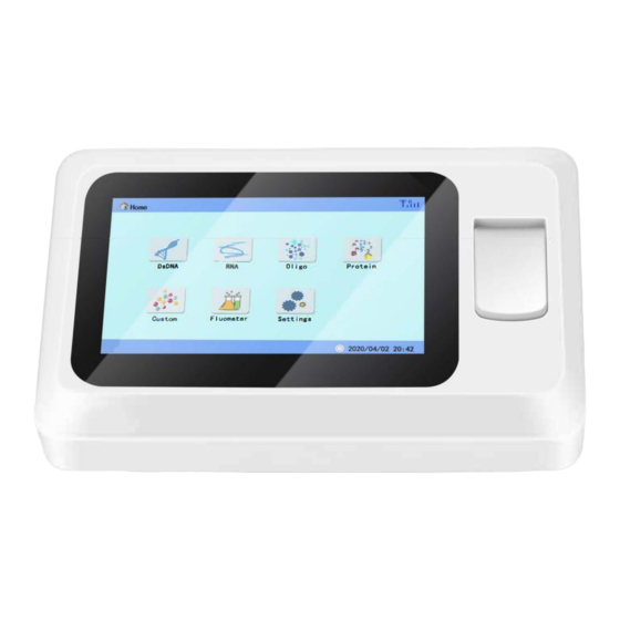
Page 9: Structure Diagram
Chapter Ⅲ Instrument composition This chapter mainly introduces the structure of the instrument and the preparations before it is turned on. When using the instrument for the first time, you should familiarize yourself with the contents of this chapter before turning it on. Structure diagram: Display Sample... - Page 10 Chapter Ⅳ Instrument installation 1. Unpacking inspection All fluorometers have been strictly inspected by the company before they are packaged and shipped. When you receive the instrument, please check carefully before unpacking, and pay attention to the following damages: ① The outer packaging is inverted or deformed; ②...
- Page 11 ③ Turn on the switch on the back of the instrument, the instrument runs self-test, and can be tested after completion. 4. Precautions for instrument operation This fluorometer can use cuvettes, 0.2mL fluorescent PCR tubes, and 0.5mL fluorescent PCR tubes for sample detection. Corresponding tube holder should be configured when using fluorescent PCR tube for detection.
- Page 12 Chapter Ⅴ Software operation Ⅰ Instrument self-test Connect the power supply, put down the upper base, press the power switch on the back of the instrument, the instrument starts and enters the self-test interface: Figure 3 Boot interface After the self-check is completed, enter the main interface of the instrument. The following sections describe each interface in detail.
- Page 13 1. Overview The 6 colored function icons in the main interface are as follows: Fluorescence detection; : detection :dsDNA ; detection :RNA ; detection :Protein ; detection :Oligo ; other detection : ; Among them, the "Fluorescence Detection" icon, click to enter, you can select the fluorescence channel configured by the instrument, and then directly detect the fluorescence value of the sample.Only fluorescence can be detected here, and there is no curve building and sample concentration analysis.
- Page 14 dsDNA detection. 2.1 dsDNA detection Click the dsDNA icon to enter the following interface (Figure 5) Standard curve selection Actual sample volume added Figure 5 Sample detection In Figure 5: Standard curve: Select the established standard curve, and the curve information will be displayed in the lower left corner.
- Page 15 b. If there is no standard curve, this item is unavailable. If you need to directly detect the fluorescence intensity of the sample, please enter the fluorescence detection interface. 2.2 Standard curve Create a standard curve After entering, a standard curve is established through the standard sample, which is used as the basis for the detection of sample concentration.
- Page 16 retrieved after deletion. ③ Save the curve: After the standard curve data detection is completed, click Save Curve to save the curve. ④ Fitting curve: After the standard curve data detection is completed, you can view the fitting curve to see the effect of standard curve establishment. ⑤...
- Page 17 Figure 7 Curve fitting Click "Curve Data" to return to the standard curve interface. Curve calibration The curve calibration function is to use a small number of samples (1-3 samples) to calibrate the curve under the condition of instrument drift, which can save the sample and operation time for establishing the standard curve while improving the sample detection accuracy.
-
Page 18: Data Record
Note: The calibration curve can be calibrated with 1-3 sample points. The principle of calibration point selection: ① Single-point calibration, with blank solution for calibration. ② Two-point calibration, using two high and low concentration sample points that can basically cover the concentration range of the entire curve. ③... - Page 19 3. Fluorescence detection Click the "Fluorescence Detection" icon to enter the following interface: Figure 10. Channel selection In this interface, the fluorescence channel configured by the instrument can be selected for sample detection. In the figure, the instrument is configured with two channels of 460nm and 625nm.
- Page 20 Figure 11 Fluorescence detection The interface can detect samples, print data, etc. Note: Printing requires an external printer to be connected. Figure 12. Data record The data recording interface saves all test data, which can be viewed, deleted, exported, printed and other operations. ─...
- Page 21 4.System setting Click the "System Settings" icon on the main menu to enter the following system settings interface: Figure 4.13. System setting 4.1 Language Click the "Language" icon, a language selection dialog box will pop up, select the desired language, and click OK to complete the language selection. Figure 4.14 Language selection ─...
- Page 22 4.2 Time setting Click the "Time" icon to enter the time setting main interface, click "Set Date", and the interface shown in Figure 4.17 will pop up. The date setting interface is as follows: Time / Date setting area Figure 4.15. Time setting Click "Set Time"...
- Page 23 Figure 4.16 Screen brightness Click the cursor area in the picture to adjust the screen brightness. 4.4 Software update Put the upgrade software in the root directory of the U disk, then insert the U disk into the machine, and then click the "software update" icon to enter the following interface: Figure 4.17 Software update Click "upper software update"...
- Page 24 4.5 Instrument information Click the "Instrument Information" button to enter the instrument information interface, and you can view the information such as the software version of the machine. Figure 4.18 Instrument information 4.6 Maintenance The maintenance function is only used in the production and maintenance links. The interface is not involved when the user uses it, and professional technicians are required to enter the password to enter the maintenance interface for instrument debugging and maintenance, which will not be described in detail here.
- Page 25 4.7 Printing Click "Print" to enter the print setting interface. The "Auto Print" function can be turned on or off in the interface. In the "Auto Print" mode, the current test result will be automatically printed after the test is completed. Figure 4.19 Print setting Note: The thermal printer is an external device, when there is no external printer, all printing functions are unavailable.
-
Page 26: Chapter Vi Maintenance, Storage And Transportation
Chapter VI Maintenance, storage and transportation Ⅰ Maintenance 1. The storage environment of the instrument should be kept dry, protected from moisture, corrosion, and away from strong electromagnetic interference sources. 2. The instrument has been installed and debugged when it leaves the factory, and users should not disassemble it at will. -
Page 27: Chapter Vii Fault Analysis And Troubleshooting
Chapter VII Fault analysis and troubleshooting Fault analysis and processing methods: Fault phenomenon Cause analysis Processing method 1. Check if the instrument is powered Fluorometer does The power supply is not normal not start 2. Check if the power plug is loose 1. - Page 28 Chapter Ⅷ Random accessories Name Unit Remarks Specification Quantity Power adapter Piece With ground Data import U disk Piece /export 0.5mLPCR tube socket Put it in the Piece instrument 0.2mLPCR tube socket Manual v1.0 Piece...
Need help?
Do you have a question about the UT-FLU5B and is the answer not in the manual?
Questions and answers